


Maintenance and Installation Installation Bladder Accumulators EHV - EHVF Accumulateurs à vessie EHV - EHVF Blasenspeicher Serie EHV - EHVF Accumulatore a sacca EHV - EHVF
Maintenance / Installation
EHV

EHV
You are on the point of intervening on an accumulator designed to contain fluids under pressure. Make sure that the accumulator is compliant with the rules existing in the country of use and that you have the following elements:
•documents delivered with the accumulator
•equipment necessary for the maintenance of accumulators, •new repair kit adapted to the accumulator
In case of difficulty, immediately contact Parker. Any improvised action can be the source of a potential danger. The equipment must only be commissioned by qualified technicians (contact Parker or its approved network).
DiSMantLinG oF aCCuMuL atoRS
Before removing the hydraulic system, the hydraulic pressure must be imperatively released from the system. Make sure that there is no residual hydraulic pressure in the accumulator.
A.Isolate the accumulator and depressurize the hydraulic system using the Parker Olaer DI depressurizing or isolating block or depressurize the hydraulic system.
B.Remove the accumulator and fix it horizontally in a vice or another securing device. Protect the shell so as not to damage it. Delimit a security area outside the alignment of openings.
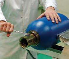
C.Unscrew the guard cap from the charging valve (photo 1).
D.Unscrew the charging valve plug (photo 2).
E.Block the hydraulic opening before complete discharge to avoid any risk of projection of liquid during the opening of the valve at the end of the discharge.
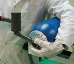
F.Discharge the gas contained in the bladder using a charging and gauge assembly until 0 is shown in the manometer (photo 3).
G.Make sure that the bladder is not charged with nitrogen by checking that the valve is open.(see diagram 1)
iMPoRtant !
If the bladder remains in contact with the valve see diagram (see diagram 2), it means that there is residual pressure. In this case:
•stop all operation
•secure the area
•contact PARKER immediately
H.Remove the single piece charging valve (photo 4) or the integrated valve mechanism or the valve core (photo 5) according to the models.
I.Remove the lock nut from the valve body and the name plate (photo 6).
By pressing on the valve body, manually push back the bladder inside the body. There must be no resistance.
IMPORTANT !
If it is not possible to push back the bladder inside, it means that there is residual pressure. In this case:
•stop all operation
•secure the area
•contact PARKER immediately
J.According to the model, remove the hydraulic vent screw and its seal (photo 7).
K.Loosen the lock nut (photo 8).
L.Manually push the fluid port body in the accumulator shell to release the spacer, O-ring and the washer (photo 9).
M.Release the rubber split ring from the fluid port body. Carefully fold it to remove it from the accumulator shell (photo 10).
N.Remove the fluid port (photo 11).
O.Remove the bladder complete with its charging valve body through the fluid port opening, taking care not to damage it (photo 12)
Carefully clean all the metallic parts of the accumulator with an organic solvent.
Visually check the condition of the components installed inside the fluid port (poppet, spring, nut and dash pot). Push the poppet head to check that it slides freely. Clean the bladder with a fluid compatible with the type of rubber, (for example, isopropyl alcohol).
Check that the surface of the bladder is not damaged.
Check that there is no corrosion, or foreign bodies inside the accumulator shell.
If the inside of the accumulator shell is protected, check the condition of the protection. For any statutory inspection, refer to the existing regulations. Replace all parts considered to be defective. The seals must be replaced (see exploded view photo).
REaSSEMBLY oF aCCuMuLatoRS
P.Squeeze the bladder to discharge the air from it (photo 13).
Q.Lubricate the inside of the shell copiously by turning it around its axis. Use either the medium used in the circuit or a similar liquid (approximately 10% of the accumulator volume for capacities up to 5 liters or 5% for higher capacities). If the liquid is low in viscosity (lower than 5 cSt), consult PARKER.
R.Lubricate the bladder and insert it into the accumulator shell.
S.Check that the bladder is not folded or twisted. For large capacity accumulators use appropriate tools (bladder extractor) (photo 14).
T.Reinstall the name plate and the lock nut. Do not tighten the lock nut (photo 15).
U.Check that the charging valve slides freely. Then insert the fluid port and the anti extrusion ring in the accumulator shell (photo 16).
V.Install the fluid port assembly on the anti extrusion ring.
W.Install the washer (A), the back up ring (B) and the spacer (C) in that order (photo 17).
X.Tighten the lock nut and make sure that the components are centered by striking lightly the fluid port body at various angles using a plastic mallet (photo 18).
Y.Tighten the lock nut (photo 19).
Z.If the model is eqquiped with the bleeder, carefully reinstall the venting screw and its new gasket, taking care to install it properly (photo 20). AA. Nitrogen side, screw the valve shell nut in position using the correct horizontal bars and tighten it (photo 21).

BB. Install the single-piece charging valve, tightening it to a torque of 1.5 mda.N or the integrated valve or the valve body tightening it to a torque of 0.03 mda.N (photo 22).
For reasons of safety it is mandatory to install a reducing valve between the bottle and the charging and gauge assembly. Before charging the accumulator with nitrogen, turn the accumulator shell to lubricate its inner walls evenly.
REMINDER! Use only nitrogen class 2.8 with a purity of 99.8% pure. It is strictly forbidden to use any other gas except nitrogen to inflate the accumulator. Explosion hazard!
Immediately after this operation, charge the bladder with nitrogen to a pressure of 1 to 1.5 bar (with the accumulator in horizontal position: see table charging process).
For the charging of the accumulator and its putting into service, refer to the instructions manual.
Finally make sure that the initial safety warnings (name plate, charging sticker, safety information…) are always legible. If this is not the case consult Parker.
Parker Hannifin Accumulator and Cooler Division EuropenEttoYaGE Et inSPECtion
iMPoRtant
Vous vous apprêtez à intervenir sur un accumulateur destiné à contenir de l’azote, des fluides sous pression. Assurez-vous que l’accumulateur est conforme à la règlementation en vigueur dans le pays d’utilisation et que vous disposez : •des documents délivrés avec l’accumulateur
•du matériel nécessaire à la maintenance des accumulateurs •d’un kit vessie neuf adapté à l’accumulateur
En cas de difficulté, contacter impérativement Parker. Toute action improvisée peut être la source d’un danger potentiel. Le montage et démontage ne doivent être confiés qu’à des techniciens qualifiés (s’adresser à Parker ou à son réseau agréé).
DEMontaGE DES aCCuMuL atEuRS
Avant de déposer l’accumulateur du circuit hydraulique, il faut impérativement relâcher la pression hydraulique du circuit et s’assurer de l’absence de pression hydraulique résiduelle au niveau de l’accumulateur.
A.Isoler l’accumulateur et décomprimer le circuit hydraulique à l’aide du bloc de décompression et d’isolement DI Parker Olaer ou décomprimer le circuit hydraulique.
B.Déposer l’accumulateur, le fixer horizontalement dans un étau ou tout autre système de fixation en protégeant le corps afin de ne pasl’endommager. Délimiter une zone de sécurité hors alignement des ouvertures.
C.Dévisser le bouchon protecteur de la valve de gonflage (photo 1).
D.Dévisser le bouchon de la valve de gonflage (photo 2).
E.Obstruer l’orifice hydraulique avant dégonflage complet pour éviter tout risque de projection fluide lors de l’ouverture de la soupape en fin de dégonflage.
F.Evacuer le gaz contenu dans la vessie à l’aide du vérificateur gonfleur équipé d’un manomètre adapté à la pression de l’accumulateur jusqu’à ce qu’il indique une pression 0 (photo 3).
G.S’assurer que la vessie n’est plus en pression d’azote en vérifiant que la soupape soit ouverte (schéma 1).
Nettoyer soigneusement toutes les pièces métalliques de l’accumulateur avec un solvant organique. Vérifier visuellement l’état des pièces montées à l’intérieur de la bouche (soupape, ressort, écrou, dash pot).
Contrôler en appuyant sur la tête de soupape que celle-ci coulisse normalement.
Nettoyer la vessie avec un fluide compatible avec la nature du caoutchouc, (alcool isopropylique, par exemple).
Vérifier que la vessie ne présente aucun défaut d’aspect.
Vérifier qu’il n’y ait aucune trace de corrosion, ni de corps étrangers à l’intérieur du corps de l’accumulateur.
Dans le cas où le corps de l’accumulateur est protégé intérieurement, vérifier le bon état de la protection. Pour toute inspection réglementaire, se référer à la réglementation en vigueur. Remplacer les pièces jugées défectueuses. Les joints doivent être obligatoirement changés (voir vue éclatée).
REMontaGE DES aCCuMuLatEuRS
P.Evacuer l’air de la vessie en la comprimant (photo13).
Q.Lubrifier abondamment l’intérieur du corps de l’accumulateur avec soit le fluide utilisé dans le circuit ou un produit compatible (environ 10% du volume de l’accumulateur pour capacité jusqu’à 5 litres ou 5% pour capacité supérieure) en le faisant tourner autour de son axe. Dans le cas d’un fluide à faible viscosité (inférieur à 5 CSt), consulter PARKER.
R.Lubrifier la vessie puis l’introduire dans le corps de l’accumulateur. (photo 14).
S.Contrôler que la vessie ne soit pas pliée ou vrillée. Dans le cas d’accumulateur de grandes capacités, utiliser l’outillage approprié (tire-vessie).
T.Remonter la plaque firme et l’écrou de fixation sans bloquer ce dernier (photo 15).
U.Vérifier le bon coulissement de la soupape. Puis introduire dans le corps de l’accumulateur, la bouche ainsi que la bague caoutchoutée (photo 16).
V.Introduire la bouche sur la bague caoutchoutée.
iMPoRtant !
Si la vessie reste en appui sur la soupape (voir schéma 2), cela signifie qu’il y aucune pression résiduelle. Dans ce cas :
•stopper toute opération
•sécuriser la zone
•contacter immédiatement PARKER
H. Retirer la valve de gonflage monobloc (photo 4) ou la valve intégrée ou l’obus de valve (photo 5) suivant modèles.
I.Retirer l’écrou de fixation du corps de valve ainsi que la plaque firme (photo 6).
En appuyant sur le corps de valve, repousser manuellement la vessie à l’intérieur du corps. Il ne doit pas y avoir de résistance
iMPoRtant ! S’il est impossible de repousser la vessie à l’intérieur, cela signifie qu’il y a une pression résiduelle. Dans ce cas :
•stopper toute opération
•sécuriser la zone
•contacter immédiatement PARKER
J.Selon modèle, déposer la vis de purge hydraulique et son joint (photo 7).
K.Dévisser l’écrou à encoches (photo 8).
L.Enfoncer manuellement la bouche dans le corps de l’accumulateur pour dégager la bague épaulée, le joint torique et la bague d’appui (photo 9).
M.Dégager la bague caoutchoutée du corps de la bouche. La replier avec précaution de manière à la sortir du corps de l’accumulateur (photo 10).
N.Extraire le corps de bouche (photo 11)
O.Extraire la vessie par l’ouverture côté bouche en veillant à ne pas l’endommager (photo 12).
W.Mettre en place dans l’ordre suivant : le joint torique (A), la bague antiextrusion (B), la bague épaulée (C) (photo 17).
X.Revisser l’écrou à encoches et assurer le centrage des pièces en frappant légèrement le corps de bouche sous plusieurs angles avec un maillet (photo 18).
Y.Serrer énergiquement l’écrou à encoches (photo 19).
Z.Si le modèle est équipé d’une bouche avec purgeur, remonter précautionneusement la vis de purge et son joint neuf, en veillant à bien l’engager (photo 20).
AA. Côté azote, visser l’écrou du corps de valve en le maintenant par les méplats appropriés puis serrer (photo 21).
BB.Mettre en place la valve de gonflage monobloc au couple de 1.5 mda.N, la valve intégrée ou l’obus de valve suivant couple 0,03 mda.N (photo 22).
Impérativement et pour des raisons de sécurité, le montage d’un détendeur entre la bouteille et le vérificateur gonfleur est obligatoire. Avant de gonfler à l’azote l’accumulateur, faire tourner autour de son axe le corps de l’accumulateur afin d’obtenir une parfaite lubrification de toute la paroi interne de celui-ci.
Rappel : Utiliser uniquement de l’azote pur à 99,8% classe 2.8. Il est formellement interdit de gonfler l’accumulateur avec tout autre fluide que l’azote.
RISQUE D’EXPLOSION !
Immédiatement après, effectuer lentement l’expansion de la vessie sous une pression d’azote de 1 à 1,5 bar (accumulateur en position horizontale: cf. tableau processus de gonflage).
Pour le gonflage de l’accumulateur et la mise en service, se conformer à la notice d’instructions.
Enfin vous assurer que les avertissements de sécurité initiaux (plaque firme, étiquette de gonflage, informations sécurité…) soient toujours lisibles. Si ce n’est pas le cas consulter Parker pour fourniture.
Parker Hannifin Accumulator and Cooler Division EuropeSie arbeiten an einem Druckspeicher, der für den Betrieb mit unter Druck stehenden Flüssigkeiten vorgesehen ist. Stellen Sie sicher, dass der Druckspeicher den Vorschriften des Einsatzlandes entspricht und Sie über Folgendes verfügen:
•die mit dem Druckspeicher gelieferten Dokumente
•die erforderliche Ausrüstung für die Wartung von Druckspeichern
•das passende neue Reparaturset für den Druckspeicher
Wenden Sie sich bei Fragen oder Problemen unverzüglich an Parker. Unbedachte Maßnahmen können zu Gefahren führen. Die Inbetriebnahme des Geräts darf nur von qualifizierten Technikern vorgenommen werden (wenden Sie sich an Parker oder einen zugelassenen Handelspartner).
DEMontaGE DES SPEiCHERS
Vor dem Ausbau des Hydrauliksystems muss unbedingt der Hydraulikdruck aus dem System abgelassen werden. Stellen Sie sicher, dass keinerlei hydraulischer Restdruck im Druckspeicher vorhanden ist.
A.Isolieren Sie den Druckspeicher und entlasten Sie das Hydrauliksystem mit dem Parker Olaer DI Druckentlastungs- und Absperrblock oder lassen Sie den Druck aus dem Hydrauliksystem ab.
B.Bauen Sie den Druckspeicher aus und fixieren Sie ihn waagerecht in einem Schraubstock oder einer anderen Fixiervorrichtung. Schützen Sie den Speicherkörper, um ihn nicht zu beschädigen. Legen Sie einen von den Öffnungen abgewandten Sicherheitsbereich fest.
C.Schrauben Sie die Schutzkappe vom Füllventil ab (Foto 1).
D.Schrauben Sie den Stopfen vom Füllventil ab (Foto 2).
E.Blockieren Sie die Hydrauliköffnung vor der vollständigen Entlastung, um die Gefahr eines Herausspritzens von Flüssigkeit beim Öffnen des Ventils zum Ende der Entlastung zu vermeiden.
F.Lassen Sie das in der Blase enthaltene Gas mit einem Prüf- und Füllgerät ab, bis das Manometer einen Wert von 0 anzeigt (Foto 3).
G.Stellen Sie sicher, dass die Blase nicht mehr mit Stickstoff beaufschlagt ist, indem Sie überprüfen, dass das Ventil geöffnet ist (siehe Schema 1).
WiCHtiG!
Wenn die Blase das Ventil weiterhin berührt (siehe Schema 2), ist ein Restdruck vorhanden. In diesem Fall:
•Den Betrieb einstellen
•Den Bereich sichern
•Unverzüglich PARKER kontaktieren
H.Entfernen Sie je nach Modell das einteilige Füllventil (Foto 4), den integrierten Ventilmechanismus oder den Gasventileinsatz (Foto 5).

I.Entfernen Sie die Haltemutter vom Ventilkörper und dem Typenschild (Foto 6).
Drücken Sie auf den Ventilkörper und schieben Sie die Blase zurück in das Gehäuse. Es darf kein Widerstand zu spüren sein. WICHTIG!
Wenn sich die Blase nicht nach innen schieben lässt, bedeutet das, dass ein Restdruck vorhanden ist. In diesem Fall:
•Den Betrieb einstellen
•Den Bereich sichern
•Unverzüglich PARKER kontaktieren
J.Entfernen Sie je nach Modell die Hydraulikentlüftungsschraube und ihre Dichtung (Foto 7).
K.Lösen sie die Haltemutter (Foto 8).
L.Drücken Sie den Flüssigkeitsanschlusskörper von Hand in den Speicherkörper, um den Distanzring, den O-Ring und die Scheibe zu lösen (Foto 9).
M.Lösen Sie den geteilten Ring vom Flüssigkeitsanschlusskörper. Drücken Sie ihn vorsichtig zusammen, um ihn vom Speicherkörper zu entfernen (Foto 10).
N.Entfernen Sie den Flüssigkeitsanschluss (Foto 11).
O.Entfernen Sie die Blase komplett mit dem Füllventilkörper durch die Öffnung des Flüssigkeitsanschlusses und achten Sie darauf, sie nicht zu beschädigen (Foto 12).
REiniGunG unD inSPEKtion
Säubern sie vorsichtig alle Metallteile des Druckspeichers mit einem organischen Lösungsmittel.
Überprüfen Sie visuell den Zustand der im Flüssigkeitsanschluss installierten Komponenten (Teller, Feder, Mutter und Ventilteller-Dämpfer).
Drücken Sie auf den Tellerkopf, um sicherzustellen, dass er sich frei bewegt. Reinigen Sie die Blase mit einer Flüssigkeit, die mit dem Gummimaterial kompatibel ist (z. B. Isopropylalkohol).
Überprüfen Sie, dass die Oberfläche der Blase nicht beschädigt ist. Vergewissern Sie sich, dass der Speicherkörper frei von Korrosion ist und sich keine Fremdkörper darin befinden.
Wenn die Innenseite des Speicherkörpers mit einem Schutz versehen ist, überprüfen Sie den Zustand des Schutzes. Beachten Sie wegen gesetzlich vorgeschriebener Inspektionen die bestehenden Vorschriften.
Ersetzen Sie alle defekten Teile. Die Dichtungen müssen ersetzt werden (siehe Explosionszeichnung).
MontaGE DES SPEiCHERS
P.Drücken Sie die Blase zusammen, um die Luft daraus zu entfernen (Foto 13).
Q.Schmieren Sie die Innenseite des Speicherkörpers reichlich, indem Sie ihn um seine Achse drehen. Verwenden Sie entweder das im Kreislauf verwendete Medium oder eine ähnliche Flüssigkeit (ca. 10 % des Druckspeichervolumens für Kapazitäten bis 5 Liter oder 5 % für höhere Kapazitäten). Wenn die Flüssigkeit eine geringe Viskosität aufweist (weniger als 5 cSt), wenden Sie sich an PARKER.
R.Schmieren Sie die Blase und führen Sie sie in den Speicherkörper ein. S.Vergewissern Sie sich, dass die Blase nicht gefaltet oder verdreht ist. Verwenden Sie für Druckspeicher mit höherer Kapazität geeignete Werkzeuge (Blasen-Ausziehvorrichtung) (Foto 14).
T.Bringen Sie das Typenschild und die Haltemutter wieder an. Ziehen Sie die Mutter nicht fest (Foto 15).
U.Stellen Sie sicher, dass sich das Füllventil frei bewegt. Setzen Sie dann den Flüssigkeitsanschluss und den Anti-Extrusionsring in den Speicherkörper ein (Foto 16).
V.Montieren Sie die Flüssigkeitsanschluss-Baugruppe auf dem AntiExtrusionsring.
W.Bringen Sie die Scheibe (A), den Stützring (B) und den Distanzring (C) in dieser Reihenfolge an (Foto 17).
X.Ziehen Sie die Haltemutter an und stellen Sie sicher, dass die Komponenten zentriert sind, indem Sie aus verschiedenen Winkeln mit einem Kunststoffhammer leicht auf den Flüssigkeitsanschlusskörper schlagen (Foto 18).
Y.Ziehen Sie Haltemutter fest (Foto 19).
Z.Wenn der Druckspeicher mit einer Entlüftung versehen ist, bringen Sie vorsichtig die Entlüftungsschraube mit einer neuen Dichtung wieder an. Achten Sie darauf, die Dichtung richtig zu montieren (Foto 20).
AA. Schrauben Sie auf der Stickstoffseite die Ventilkörpermutter an und ziehen Sie sie fest (Foto 21).
BB. Montieren Sie das einteilige Füllventil (Anzugsmoment: 1,5 mda.N), das integrierte Ventil oder den Ventilkörper (Anzugsmoment: 0,03 mda.N) (Foto 22).
Aus Sicherheitsgründen muss zwischen der Flasche und dem Prüfund Füllgerät ein Entlastungsventil montiert sein.
Bevor Sie den Druckspeicher mit Stickstoff füllen, drehen Sie den Speicherkörper, um die Innenwände gleichmäßig zu schmieren.
ERINNERUNG! Verwenden Sie nur Stickstoff der Klasse 2.8 mit einer Reinheit von 99,8 %. Es ist strengstens untersagt, den Druckspeicher mit anderen Gasen als Stickstoff zu befüllen . EXPLoSionSGEFaHR!
Beaufschlagen Sie die Blase unmittelbar danach mit Stickstoff mit einem Druck von 1 bis 1,5 bar (mit dem Druckspeicher in horizontaler Ausrichtung: siehe Tabelle „Füllvorgang“).
Hinweise zum Befüllen und zur Inbetriebnahme des Druckspeichers können Sie der Betriebsanleitung entnehmen.
Stellen Sie abschließend sicher, dass alle Warnhinweise und -schilder (Typenschild, Aufkleber für Befüllung, Sicherheitshinweise…) gut lesbar sind. Wenden Sie sich andernfalls an Parker.


Pezzi di ricambio
gas Valvola del gas
Bussola completa
porta del fluido
Ghiera a intagli O-Ring porta del fluido
*These parts are not delivered in the spare parts kit (complete repair kit)
*Ces pièces ne sont pas livrées dans le kit de rechange
*These parts are not delivered in the spare parts kit (complete repair kit)

*Diese Teile sind nicht in der Ersatz Kit geliefert
*Ces pièces ne sont pas livrées dans le kit de rechange
*Questi parti non vengono forniti nel kit di ricambion
*Diese Teile sind nicht in der Ersatz Kit geliefert
Charging Process / Processus de gonflage / Befüllungsvorgang /Processo di gonfiare
*Questi parti non vengono forniti nel kit di ricambion
Pre-charging time 0 to 1.5 bar in seconds
Temps de précharge de 0 à 1.5 bar en secondes Vorfüllzeit von 0 bis 1,5 bar in Sekunden
Tempo di precarica da 0 a 1.5 bar in secondi
When above 1.5 bar, continue charging to the required pressure. Au-dessus de la valeur 1.5 bar, continuer le gon lage à la valeur choisie.
Bei Überschreiten des Wertes von 1,5 bar das Vorfüllen bis zum gewünschten Wert fortsetzen. Al di sotto del valore di 1.5 bar, continuare il goniaggio al valore scelto.
AE – United Arab Emirates, Dubai Tel: +971 4 8127100 parker.me@parker.com
AT – Austria, Wiener Neustadt
Tel: +43 (0)2622 23501-0 parker.austria@parker.com
AT – Eastern Europe, Wiener Neustadt
Tel: +43 (0)2622 23501 900 parker.easteurope@parker.com
AZ – Azerbaijan, Baku Tel: +994 50 22 33 458 parker.azerbaijan@parker.com
BE/LU – Belgium, Nivelles Tel: +32 (0)67 280 900 parker.belgium@parker.com
BG – Bulgaria, Sofia Tel: +359 2 980 1344 parker.bulgaria@parker.com
BY – Belarus, Minsk Tel: +375 17 209 9399 parker.belarus@parker.com
CH – Switzerland, Etoy
Tel: +41 (0)21 821 87 00 parker.switzerland@parker.com
CZ – Czech Republic, Klecany
Tel: +420 284 083 111 parker.czechrepublic@parker.com
DE – Germany, Kaarst
Tel: +49 (0)2131 4016 0 parker.germany@parker.com
DK – Denmark, Ballerup
Tel: +45 43 56 04 00 parker.denmark@parker.com
ES – Spain, Madrid
Tel: +34 902 330 001 parker.spain@parker.com
FI – Finland, Vantaa
Tel: +358 (0)20 753 2500 parker.finland@parker.com
FR – France, Contamine s/Arve Tel: +33 (0)4 50 25 80 25 parker.france@parker.com
GR – Greece, Athens
Tel: +30 210 933 6450 parker.greece@parker.com
HU – Hungary, Budaoers Tel: +36 23 885 470 parker.hungary@parker.com
IE – Ireland, Dublin Tel: +353 (0)1 466 6370 parker.ireland@parker.com
IT – Italy, Corsico (MI) Tel: +39 02 45 19 21 parker.italy@parker.com
KZ – Kazakhstan, Almaty Tel: +7 7273 561 000 parker.easteurope@parker.com
NL – The Netherlands, Oldenzaal Tel: +31 (0)541 585 000 parker.nl@parker.com
NO – Norway, Asker Tel: +47 66 75 34 00 parker.norway@parker.com
PL – Poland, Warsaw Tel: +48 (0)22 573 24 00 parker.poland@parker.com
PT – Portugal, Leca da Palmeira Tel: +351 22 999 7360 parker.portugal@parker.com
RO – Romania, Bucharest Tel: +40 21 252 1382 parker.romania@parker.com
RU – Russia, Moscow Tel: +7 495 645-2156 parker.russia@parker.com
SE – Sweden, Spånga
Tel: +46 (0)8 59 79 50 00 parker.sweden@parker.com
SK – Slovakia, Banská Bystrica Tel: +421 484 162 252 parker.slovakia@parker.com
SL – Slovenia, Novo Mesto Tel: +386 7 337 6650 parker.slovenia@parker.com
TR – Turkey, Istanbul Tel: +90 216 4997081 parker.turkey@parker.com
UA – Ukraine, Kiev Tel +380 44 494 2731 parker.ukraine@parker.com
UK – United Kingdom, Warwick Tel: +44 (0)1926 317 878 parker.uk@parker.com
ZA – South Africa, Kempton Park Tel: +27 (0)11 961 0700 parker.southafrica@parker.com
North America
CA – Canada, Milton, Ontario
Tel: +1 905 693 3000
US – USA, Cleveland (industrial)
Tel: +1 216 896 3000
US – USA, Elk Grove Village (mobile)
Tel: +1 847 258 6200
Asia Pacific
AU – Australia, Castle Hill
Tel: +61 (0)2-9634 7777
CN – China, Shanghai
Tel: +86 21 2899 5000
HK – Hong Kong
Tel: +852 2428 8008
IN – India, Mumbai
Tel: +91 22 6513 7081-85
JP – Japan, Fujisawa
Tel: +81 (0)4 6635 3050
KR – South Korea, Seoul
Tel: +82 2 559 0400
MY – Malaysia, Shah Alam
Tel: +60 3 7849 0800
NZ – New Zealand, Mt Wellington
Tel: +64 9 574 1744
SG – Singapore
Tel: +65 6887 6300
TH – Thailand, Bangkok
Tel: +662 717 8140
TW – Taiwan, Taipei
Tel: +886 2 2298 8987
South America
AR – Argentina, Buenos Aires
Tel: +54 3327 44 4129
BR – Brazil, Cachoeirinha RS
Tel: +55 51 3470 9144
CL – Chile, Santiago
Tel: +56 2 623 1216
MX – Mexico, Apodaca
Tel: +52 81 8156 6000
EMEA Product Information Centre
Free phone: 00 800 27 27 5374 (from AT, BE, CH, CZ, DE, DK, EE, ES, FI, FR, IE, IL, IS, IT, LU, MT, NL, NO, PL, PT, RU, SE, SK, UK, ZA)
US Product Information Centre
Toll-free number: 1-800-27 27 537 www.parker.com