P1/PD Series: 18cc to 140cc Medium
Pressure Axial Piston Pumps
Variable Displacement – Service Information
Bulletin HY28 -2665 - 02/SVC/EN
Effective: February 19, 2015
The product information, specifcations, and descriptions contained in this publication have been compiled for the use and convenience of our customers from information furnished by the manufacturer; and we can not, and do not, accept any responsibility for the accuracy or correctness of any description, calculation, specifcation, or information contained herein. No such description, calculation, specifcation, or information regarding the products being sold has been made part of the basis of the bargain, nor has same created or amounted to an express warranty that the products would conform thereto. We are selling the goods and merchandise illustrated and described on this publication on an “as is” basis, and disclaim any implied warranty, including any warranty of merchantability or warranty of ftness for any particular purpose whatsoever, with respect to the goods and merchandise sold. All manufacturer warranties shall be passed on to our customers, but we shall not be responsible for special, indirect, incidental, or consequential damages resulting from the use of any of the products or information contained or described on this publication. Further, we reserve the right to revise or otherwise make product improvements at any time without notifcation.
WARNING - USER RESPONSIBILITY
FAILURE OR IMPROPER SELECTION OR IMPROPER USE OF THE PRODUCTS DESCRIBED HEREIN OR RELATED ITEMS CAN CAUSE DEATH, PERSONAL INJURY AND PROPERTY DAMAGE.
This document and other information from Parker-Hannifin Corporation, its subsidiaries and authorized distributors provide product or system options for further investigation by users having technical expertise.
The user, through its own analysis and testing, is solely responsible for making the final selection of the system and components and assuring that all performance, endurance, maintenance, safety and warning requirements of the application are met. The user must analyze all aspects of the application, follow applicable industry standards, and follow the information concerning the product in the current product catalog and in any other materials provided from Parker or its subsidiaries or authorized distributors.
To the extent that Parker or its subsidiaries or authorized distributors provide component or system options based upon data or specifications provided by the user, the user is responsible for determining that such data and specifications are suitable and sufficient for all applications and reasonably foreseeable uses of the components or systems.
OFFER OF SALE
The items described in this document are hereby offered for sale by Parker-Hannifin Corporation, its subsidiaries or its authorized distributor This offer and its accepteance are governed by the provisions stated in the detailed "Offer of Sale" elsewhere in this document.
2
Parker Hannifn Corporation Hydraulic Pump and Power Systems Division Marysville, Ohio USA P1/PD Maintenance 3
Bulletin HY28-2665-02/SVC/EN General Information……………………………………………………………………………………… ..........................4 Start up procedure…………………………………………………………………………………………..... ...................5 Troubleshooting……………………………………………………………………………………………..... ....................6 18cc, Model Ordering Code…………………………………………………………...... ...............................................8 28cc, Model Ordering Code…………………………………………………………...... ...............................................9 45cc, Model Ordering Code…………………………………………………………...... .............................................10 60cc, Model Ordering Code…………………………………………………………...... .............................................11 75cc, Model Ordering Code…………………………………………………………...... .............................................12 100cc, Model Ordering Code…………………………………………………………...... ...........................................13 140cc, Model Ordering Code…………………………………………………………...... ...........................................14 Technical data………………………………………………………………………………………………... ...................15 Parts Data 018 & 028 pump exploded view………………………………………………………….............................................16 045 pump exploded view…………………………………………………………………............................. ...............17 Parts list for 018, 028, 045…………………………..…………………………………………………................... .......18 060, 075, 100 & 140 pump exploded view...……………………………………………............................ ................20 Parts list for 060, 075, 100, 140…………………………..…………………………………………….................... .....21 Electronic Control Exploded View...……………………………………………............................ .............................22 Parts list for Electronic Control…………………………..…………………………………………….................... ......23 Case to inlet check valves…………………………………………………………………............................ ...............24 Volume stop…………………………………………………………………………………............................ ...............25 Seal and parts kits……………….…………………………………………………………............................ ..........26-27 L-compensator………………………………………………………………………………........................... ..........28-29 C-compensator…………………….…………………………………………………………..................... ...................30 AE, AF, AL, AM,AN compensator.…………………………………………………………........................... ...............31 Assembly/Disassembly information Compensator disassembly/inspection.……………………………………………………............................ .............32 Compensator assembly………….…………………………………………………………............................ ..............33 018, 028, 045 disassembly…………………………………………………………………............................ ..............34 018, 028, 045 Inspection…………………………………………………………………............................... ..............37 018, 028, 045 rework limits…………………………………………………………………............................ .............38 018, 028, 045 assembly…………………………………………………………………................................. .............39 018, 028, 045 assembly tools………………………………………………………………............................ .............42 018, 028, 045 test procedure.………………………………………………………………............................ .............44 060, 075, 100, 140 disassembly..…………………………………………………………............................ ...............46 060, 075, 100, 140 inspection…..…………………………………………………………............................ ..............48 060, 075, 100, 140 rework limits..…………………………………………………………............................ ..............49 060, 075, 100, 140 assembly…...…………………………………………………………...........................................50 060, 075, 100, 140 assembly tools..………………………………………………………............................ ..............54 060, 075, 100, 140 test procedure…………………………………………………………............................ .............56 Conversions and formulas………...…………………………………………………………........................................59 Offer of sale………………………....…………………………………………………………........................................63
Medium Pressure Axial Piston Pumps Contents Contents
Bulletin HY28-2665-02/SVC/EN
General Information
MOUNTING
SHAFT INFORMATION
Medium Pressure Axial Piston Pumps P1/PD Maintenance
These pumps are designed to operate in any position. The pump shaft must be in alignment with the shaft of the source driver and should be checked with a dial indicator. The mating pilot bore and coupling must be concentric. This concentricity is particularly important if the shaft is rigidly connected to the driven load without a fexible coupling.
Splined: The shafts will accept a maximum misalignment of 0.15mm, 0.005 inch, total indicator reading. Angular misalignment at the external and internal spline axis must be less than ± 0,002 mm per mm of shaft radius, ± 0.002 inches per inch of shaft radius. The coupling interface must be lubricated. PARKER recommends lithium molydisulfde or similar grease. The internal coupling should be hardened to Rc 27-34 and must conform to SAE-J498c, class 5 fat root side ft.
Keyed: High strength heat treated keys must be used. Replacement keys must be hardened to 27-34 Rc. The key corners must be chamfered 0.81-1.0 mm, 0.032”-0.040”, at 45° to clear radii that exist in the keyway.
SIDE LOAD CAPABILITY
FLUID CONNECTIONS
The P1/PD series is designed for inline-drive. Side loading on the shaft is not recommended. If this is unavoidable consult your nearest PARKER representative.
Connect inlet and outlet lines to the port block of the pump. The maximum case pressure is 2 bar (30 psi) continuous, 4 bar (60 psi) intermittent. The case pressure must never exceed inlet pressure by more than .5 bar (7 psi). When connecting case drain line make certain that drain plumbing passes above highest point of the pump before passing to the reservoir. The case leakage line must be of suffcient size to prevent back pressure in excess of 2 bar (30 psi) and returned to the reservoir below the surface of the oil as far from the supply inlet as possible. All fuid lines, whether pipe, tubing, or hose must be adequate size and strength to assure free fow through the pump. An undersize inlet line will prevent the pump from operating properly at full rated speed. An undersize outlet line will cause back pressure and cause heat generation and increased noise. Flexible hose lines are recommended. If rigid piping is used, the workmanship must be accurate to eliminate strain on the pump port block or to the fuid connections. Sharp bends in the lines must be eliminated wherever possible. All system piping must be cleaned and fushed before installing pump. Make sure the entire hydraulic system is free of dirt, lint, scale, or other foreign material.
Caution: Do not use galvanized pipe. Galvanized coating can fake off with continued use.
SYSTEM RELIEF VALVES
RECOMMENDED FLUIDS
Although the P1/PD series pumps have very fast off-stroke compensator response, system relief valves are recommended in all cases for safety considerations.
The fuid recommended for use in these pumps has a petroleum base and contains agents which provide oxidation inhibition and anti-rust, anti-foam and de-aerating properties as described in PARKER standard HF-1. Where anti-wear additive fuids are specifed, see PARKER standard HF-0.
VISCOSITY INDEX
TEMPERATURE
MAINTENANCE
90 V. I. minimum. Higher values extend the range of operating temperature but may reduce the service life of the fuid.
Determined by the viscosity characteristics of the fuid used. Because high temperatures degrade seals, reduce the service life of the fuid and create hazards, fuid temperature should not exceed 110°C (230°F) at the case drain.
The pump is self-lubricating and preventative maintenance is limited to keeping system fuid clean by changing flters frequently. Keep all fttings and screws tight. Do not operate at pressures and speeds in excess of the recommended limit. If the pump does not operate properly, check the troubleshooting chart before attempting to overhaul the unit. Overhauling may be accomplished by referring to the disassembly, rework limits of wear parts, and assembly procedures as provided in this service manual.
FLUID CLEANLINESS
Fluid must be cleaned before and continuously during operation, by flters that maintain a cleanliness level of ISO 20/18/14. Better cleanliness levels will signifcantly extend the life of the components. As contaminant generation may vary with each application, each must be analyzed to determine proper fltration to maintain the required cleanliness level.
Parker Hannifn Corporation Hydraulic Pump and Power Systems Division Marysville, Ohio USA
4
Bulletin HY28-2665-02/SVC/EN
General Information
STARTUP PROCEDURE FOR NEW INSTALLATIONS
Medium Pressure Axial Piston Pumps P1/PD Maintenance
• Read and understand the instruction manual.
• Identify components and their function.
• Visually inspect components and lines for possible damage.
• Insure that all necessary ports are properly connected.
• Check reservoir for cleanliness. Drain and clean as required.
• Check fuid level and fll as required with fltered fuid to a minimum ISO cleanliness level of 20/18/14.
• Fill pump case with clean oil prior to starting.
• If pump is mounted vertically with the shaft up, bleed the air out the D1 drain port located near the mounting fange.
• Check alignment of drive.
• Check oil cooler and activate it, if included in circuit. Check fuid temperature.
• Reduce pressure settings of compensator and relief valve. Make sure accurate pressure readings can be made at appropriate places.
• If solenoids in system, check for actuation.
• Jog the pump drive. Check for proper shaft rotation. Make sure pump flls properly.
• Start the pump drive.
• Bleed system of air. Recheck fuid level.
• Cycle unloaded machine at low pressure and observe actuation (at low speed, if possible).
• Increase pressure settings gradually in steps. Check for leaks in all lines especially in pump and motor inlet lines.
• Make correct pressure adjustments.
• Gradually increase speed. Be alert for trouble as indicated by changes in sounds, system shocks, and air in fuid.
• Equipment is operational.
Parker Hannifn Corporation
Hydraulic Pump and Power Systems Division Marysville, Ohio USA
5
Typical Ajustment Ranges and Initial Settings (unless customer specified at time of order) Function Adjustment range Adjustment valueRecommended or Initial Setting Pressure compensators "C0" 80-280 bar (1160-4060 PSI)40 bar/turn (580 PSI/turn)Factory supplied at minimum "C1" 20-80 bar (290-1160 PSI)18.6 bar/turn (260PSI/turn)Factory supplied at minimum "AM" 80-280 bar (1160-4060 PSI)40 bar/turn (580 PSI/turn)Factory supplied at minimum Load sense pressure "L0" 8-35 bar (116-500 PSI)28 bar/turn (410 PSI/turn) 24 bar (350 PSI) Differential pressure "AM" 37 bar (540 PSI)Adjustment not recommendedFactory Set do not adjust Maximum Volume stop 018 100-40% 9% per turn (1.6 cc/turn) 100% 028 100-40% 8.2% per turn (2.3 cc/turn) 100% 045 100-20% 7.5% per turn (3.4 cc/turn) 100% 060 100-30% 6.8% per turn (4.1 cc/turn) 100% 075 100-35% 6.2% per turn (4.65 cc/turn) 100% 100 100-50% 5.5% per turn (5.5 cc/turn) 100% 140 100-50% 4.8% per turn (6.72 cc/turn) 100% Minimum Volume stop 018 0-68% 10% per turn (1.8 cc/turn) 0% 028 0-40% 9% per turn (2.6 cc/turn) 0% 045 0-40% 8.2% per turn (3.7 cc/turn) 0% 060 0-50% 4.6% per turn (2.76 cc/turn) 0% 075 0-45% 4.3% per turn (3.23 cc/turn) 0% 100 0-45% 3.9% per turn (3.9 cc/turn) 0% 140 0-25% 3.3% per turn (4.62 cc/turn) 0%
Bulletin HY28-2665-02/SVC/EN
Trouble Shooting
Medium Pressure Axial Piston Pumps P1/PD Maintenance
Component problems and circuit problems are often interrelated. An improper circuit may operate with apparent success but will cause failure of a particular component within it. The component failure can be the effect, not the cause of the problem. This general guide is offered to help in locating and eliminating the cause of problems by studying their effects.
Effect of TroublePossible Cause Fault Which Needs Remedy
leak in inlet line
low fuid level
turbulent fuid
air in fuid
return lines above fuid level gas leak from accumulator
excessive pressure drop in the inlet line from a pressurized reservoir inlet line strainer acting as air trap
fuid too cold
fuid too viscous
cavitation in rotating group
noisy pump
erosion on barrel ports and port plate
misaligned shaft
fuid too heavy shaft speed to high inlet line too small inlet strainer too small inlet strainer too dirty operating altitude too high inlet pressure too low
faulty installation
distortion in mounting axial interference
faulty coupling
excessive overhung loads
piston and shoe looseness or failure bearing failure
mechanical fault in pump
incorrect port plate rotation eroded or worn parts in the displacement control
air in fuid see noisy pump above cavitation see noisy pump above
pressure shocks
compensator instability
cogging load
mechanical considerations worn relief valve needed repairs
worn compensatorreplace slow response in check valves replace or relocate
excessive decompression energy rates improve decompression control barrel blow-off rotating group worn, excessive case pressure
excessive line capacitance (line volume, line stretch, acumulator effects)
reduce line size or lengths
eliminate hose
Parker Hannifn Corporation Hydraulic Pump and Power Systems Division Marysville, Ohio USA
6
Bulletin HY28-2665-02/SVC/EN
Trouble Shooting
Effect of TroublePossible Cause
Medium Pressure Axial Piston Pumps P1/PD Maintenance
Fault Which Needs Remedy
excessive loads reduce pressure settings reduce speeds
improper flter maintenance flters too coarse
contaminant particles in fuid
introduction of dirty fuid to system
reservoir openings
improper reservoir breather
improper line replacement
high wear in pump
improper fuid
fuid too thin or thick for operating temperature range breakdown of fuid with time/temperature/heating effects incorrect additives in new fuid
destruction of additive effectiveness with chemical aging
improper repair incorrect parts
incorrect procedures, dimensions, fnishes
condensation
faulty breather/strainer
heating of fuid
unwanted water in fuid
heat exchanger leakage
faulty clean-up practice water in makeup fuid
excessive pump leakage
recheck case drain fow and repair as required fuid too thin
improper assembly, port timing
relief valve set too low (compared to load or to compensator) instability caused by back pressure, worn parts
compensator set too high (compared to relief) worn parts
pump too large for fuid needs
heat exchanger
select smaller pump displacement
water turned off or too little fow water too hot
fan clogged or restricted
effciency reduced by mud or scale deposits intermittent hydraulic fuid fow
reservoir
too little fuid improper baffes insulating air blanket that prevents heat rejection heat pickup from adjacent equipment
Parker Hannifn Corporation Hydraulic Pump and Power Systems Division Marysville, Ohio USA
7
Bulletin HY28-2665-02/SVC/EN
P1/PD 18cc, Model Ordering Code
Medium Pressure Axial Piston Pumps P1/PD Maintenance
018 P S 5 A 00
Control Options
C0 Pressure limiter
1160.30 - 4061.05 PSI (80 - 280 bar)
C1 Pressure limiter 290.08 - 1160.30 PSI (20 - 80 bar)
L0 Load sensing 145.04 - 435.11 PSI ∆P (10 - 30 bar ∆P) with pressure limiter 1160.30 - 4061.05 PSI (80 - 280 bar)
L1 Load sensing 145 - 435 PSI ∆P (10 - 30 bar ∆P) with pressure limiter 290 - 1450 PSI (20 - 100 bar)
Port Orientation
E End Ports
R Side ported with ripple chamber
T Side ported with Thru-Drive
Adjustable Displacement Stops
0 None
1 Adjustable maximum displacement stop
2 Adjustable minimum displacement stop
B
Work Ports with BSPP Aux Ports
L2 Load sensing 145.04 - 435.11 PSI ∆P (10 - 30 bar ∆P) with bleed & pressure limiter 1160.30 - 4061.05 PSI (80 - 280 bar)
AN* Pilot operated pressure limiter with ISO4401 interface & SAE 4 Vent Port
AM Pilot operated pressure limiter with mechanical adjustment and SAE 4 Vent Port
AE Pilot operated pressure limiter with mechanical and electrical adjustment 12 VDC
AF Pilot operated pressure limiter with mechanical and electrical adjustment 24 VDC
## See chart below for electronic control options
*Not functional control as such
Additional Control Options
0 No other options
2 Displacement sensor **
**Mandatory with “W**”, “X**”, “Y**”, “Z**” “*D*” and “*Y*”
3 Adjustable maximum and minimum displacement stop
Port Type
0 Flange Ports*
2 Threaded Ports
*With Thru-Drive Only
Thru-Drive Mounting Pad/Coupling
0 No Thru-Drive
A SAE 82-2(A), 16(A), 9T coupling
H SAE 82-2(A), 19(--), 11T coupling
P Electronic valve with zero displacement default T Electronic valve with max displacement default
S Electronic valve with zero displacement default and hydromechanical Pmax
U Electronic valve with max displacement default and hydromechanical Pmax
W Electronic valve with zero displacement default (CANBUS compatible)
X Electronic valve with max displacement default (CANBUS compatible)
Y Electronic valve with zero displacement default and hydromechanical Pmax (CANBUS compatible)
Z Electronic valve with max displacement default and hydromechanical Pmax (CANBUS compatible)
only available with *D* and *Y*
Parker Hannifn Corporation
Hydraulic Pump and Power Systems Division
Marysville, Ohio USA
8
Adjustable Displacement Stops Port Type Thru-Drive Mounting Pad/Coupling Paint Special Features Pump Series Displacement 18cc/rev. (1.10 in³/rev) Mounting & Ports Open Circuit Port Orientation Shaft Rotation Design Letter Additional Control Options Control Options Configuration Single Shaft Seal Shaft Options Fluorocarbon Seal Material
*** W, X, Y
Z
0 No ECU D Proportional displacement control Y Proportional pressure control
Control Options # # Paint 00 No Paint PB Black Paint Shaft Options 01 Splined shaft - SAE 19-4 11T
Keyed shaft - SAE 19-1 .75" Dia.
ISO
Dia.
and
Electronic
02
04
keyed 20MM
06 Splined shaft - SAE A 9T*
Rotation R Clockwise L Counterclockwise Pump Series P1 Mobile PD Industrial
M Mobile (P1) S Industrial (PD)
& Ports
SAE A Pilot SAE Threaded Work Ports with SAE Aux Ports A SAE A Pilot Metric Work Ports with BSPP Aux Ports
ISO - 80mm Pilot Metric Work
with Metric Aux Ports
*Not available with Thru-Drive Shaft
Configuration
Mounting
S
M
Ports
ISO
Metric
- 80mm Pilot
Bulletin HY28-2665-02/SVC/EN
P1/PD 28cc, Model Ordering Code
Medium Pressure Axial Piston Pumps P1/PD Maintenance
028 P S 5 A 00
Control Options
C0 Pressure limiter 1160.30 - 4061.05 PSI (80 - 280 bar)
C1 Pressure limiter 290.08 - 1160.30 PSI (20 - 80 bar)
L0 Load sensing 145.04 - 435.11 PSI ∆P (10 - 30 bar ∆P) with pressure limiter 1160.30 - 4061.05 PSI (80 - 280 bar)
L1 Load sensing 145 - 435 PSI ∆P (10 - 30 bar ∆P) with pressure limiter 290 - 1450 PSI (20 - 100 bar)
L2 Load sensing 145.04 - 435.11 PSI ∆P (10 - 30 bar ∆P) with bleed & pressure limiter 1160.30 - 4061.05 PSI (80 - 280 bar)
AN* Pilot operated pressure limiter with ISO4401 interface & SAE 4 Vent Port
AM Pilot operated pressure limiter with mechanical adjustment and SAE 4 Vent Port
AE Pilot operated pressure limiter with mechanical and electrical adjustment 12 VDC
AF Pilot operated pressure limiter with mechanical and electrical adjustment 24 VDC
## See chart below for electronic control options
*Not functional control as such
Additional Control Options
0 No other options
2 Displacement sensor ** **Mandatory with “W**”, “X**”, “Y**”, “Z**” “*D*” and “*Y*”
Port Orientation
E End Ports
R Side ported with ripple chamber
T Side ported with through drive
Adjustable Displacement Stops* (For E & R Port Orientation Only)
0 None
1 Adjustable maximum displacement stop
2 Adjustable minimum displacement stop
3 Adjustable maximum and minimum displacement stop
*Not available with Thru-Drive
Port Type
0 Flange Ports
2 Threaded Ports
Thru-Drive Mounting Pad/Coupling
0 No Thru-Drive
A SAE 82-2 (A), 16 (A), 9T coupling
H SAE 82-2 (A), 19 (--), 11T coupling
B SAE 101-2 (B), 22 (B) , 13T coupling
Q SAE 101-2 (B), 25 (B-B), 15T coupling
Parker Hannifn Corporation
Hydraulic Pump and Power Systems Division
Marysville, Ohio USA
P Electronic valve with zero displacement default T Electronic valve with max displacement default
S Electronic valve with zero displacement default and hydromechanical Pmax
U Electronic valve with max displacement default and hydromechanical Pmax
W Electronic valve with zero displacement default (CANBUS compatible)
X Electronic valve with max displacement default (CANBUS compatible)
Y Electronic valve with zero displacement default and hydromechanical Pmax (CANBUS compatible)
Z Electronic valve with max displacement default and hydromechanical Pmax (CANBUS compatible)
9
Adjustable Displacement Stops Port Type Thru-Drive Mounting Pad/Coupling Paint Special Features Pump Series Displacement 28cc/rev. (1.71 in³/rev) Mounting & Ports Open Circuit Port Orientation Shaft Rotation Design Letter Additional Control Options Control Options Configuration Single Shaft Seal Shaft Options Fluorocarbon Seal Material
*** W, X, Y and Z
0 No ECU D Proportional displacement control Y Proportional pressure control
Control Options # # Paint 00 No Paint PB Black Paint Shaft Options 01 Splined shaft - SAE B-B 15T
Keyed shaft - SAE B-B 1" Dia. 04 ISO keyed 25MM Dia. 08 Splined shaft - SAE B 13T
Rotation R Clockwise L Counterclockwise Pump Series P1 Mobile PD Industrial Configuration M Mobile (P1) S Industrial (PD) Mounting & Ports S SAE B Pilot SAE Work Ports with SAE Aux Ports A SAE B Pilot Metric Work Ports with BSPP Aux Ports M ISO - 100MM Pilot Metric Work Ports with Aux Ports B ISO - 100MM Pilot Metric Work Ports with BSPP Aux Ports
only available with *D* and *Y*
Electronic
02
Shaft
Bulletin HY28-2665-02/SVC/EN
P1/PD 45cc, Model Ordering Code
Medium Pressure Axial Piston Pumps P1/PD Maintenance
045 P S 5 A 00
P1 Mobile
Pump Series
Control Options
C0 Pressure limiter 1160.30 - 4061.05 PSI (80 - 280 bar)
Port Orientation
E End Ports
R Side ported with ripple chamber
Mounting & Ports
S SAE B Pilot with SAE Threaded or Flange Work Ports with SAE Aux Ports
A SAE B Pilot with Metric Threaded or Metric Flange Work Ports with BSPP Aux Ports
M ISO - 100MM Pilot Metric Threaded or Metric Flange Work Ports with Aux Ports
B ISO - 100MM Pilot Metric Threaded or Metric Flange Work Ports with Aux Ports
Shaft Options
01 Splined shaft - SAE B-B 15T
02 Keyed shaft - SAE B-B 1" Dia.
04 ISO keyed 25MM Dia.
08 Splined shaft - SAE B 13T
Shaft Rotation
R Clockwise
L Counterclockwise
PD Industrial Confguration
M Mobile (P1)
S Industrial (PD)
U Universal (SAE Mounting Option, S, Only)
C1 Pressure limiter 290.08 - 1160.30 PSI (20 - 80 bar)
L0 Load sensing 145.04 - 435.11 PSI ∆P (10 - 30 bar ∆P) with pressure limiter
L1
L2
1160.30 - 4061.05 PSI (80 - 280 bar)
Load sensing 145 - 435 PSI ∆P (10 - 30 bar ∆P) with pressure limiter
290 - 1450 PSI (20 - 100 bar)
Load sensing 145.04 - 435.11 PSI ∆P (10 - 30 bar ∆P) with bleed & pressure limiter
1160.30 - 4061.05 PSI (80 - 280 bar)
AN* Pilot operated pressure limiter with ISO4401 interface & SAE 4 Vent Port
AL Pilot operated pressure limiter with Load sensing (only available with “T” Torque Limiter option, i.e. “ALT”)
AM Pilot operated pressure limiter with mechanical adjustment and SAE 4 Vent Port
AE Pilot operated pressure limiter with mechanical and electrical adjustment 12 VDC
AF Pilot operated pressure limiter with mechanical and electrical adjustment 24 VDC
## See chart below for electronic control options
*Not functional control as such
Additional Control Options
0 No other options
2 Displacement sensor **
T Torque Limiter Control (Used with AM, AN or AL control options)
**Mandatory with “W**”, “X**”, “Y**”, “Z**” “*D*” and “*Y*”
T Side ported with through drive
Adjustable Displacement Stops*
(For E & R Port Orientation Only)
0 None
1 Adjustable maximum displacement stop
2 Adjustable minimum displacement stop
3 Adjustable maximum and minimum displacement stop
*Not available with Thru-Drive
Port Type
0 Flange Ports
2 Threaded Ports
16 (A), 9T coupling
H SAE 82-2 (A), 19 (--), 11T coupling
B SAE 101-2 (B), 22 (B), 13T coupling
Q SAE 101-2 (B), 25 (B-B), 15T coupling
P Electronic valve with zero displacement default
T Electronic valve with max displacement default
S Electronic valve with zero displacement default and hydromechanical Pmax
U Electronic valve with max displacement default and hydromechanical Pmax
W Electronic valve with zero displacement default (CANBUS compatible)
X Electronic valve with max displacement default (CANBUS compatible)
Y Electronic valve with zero displacement default and hydromechanical Pmax (CANBUS compatible)
Z Electronic valve with max displacement default and hydromechanical Pmax (CANBUS compatible)
W, X, Y and Z only available with *D* and *Y*
Parker Hannifn Corporation
Hydraulic Pump and Power Systems Division
Marysville, Ohio USA
10
Adjustable Displacement Stops Port Type Thru-Drive Mounting Pad & Coupling Paint Special Features Pump Series Displacement 45cc/rev. (2.75 in³/rev) Mounting & Ports Open Circuit Port Orientation Shaft Rotation Design Letter Additional Control Options Control Options Configuration Single Shaft Seal Shaft Options Fluorocarbon Seal Material
0 No ECU D Proportional displacement control Y Proportional pressure control Electronic Control Options # # Paint 00 No Paint PB Black Paint Thru-Drive Mounting Pad/Coupling 0 No Thru-Drive A SAE 82-2 (A),
***
Bulletin HY28-2665-02/SVC/EN
P1/PD 60cc, Model Ordering Code
060
P1 Mobile
PD Industrial
Open Circuit
P Open Circuit (One Side of Center)
X Open Circuit (100% over Center)
Mounting & Ports
S SAE C Pilot SAE Flange Connection Ports with SAE Aux Ports
A SAE C Pilot Metric Flange Connection Ports with BSPP Aux Ports
M ISO - 125MM Pilot Metric Flange Connection Ports with Metric Aux Ports
B ISO - 125MM Pilot, Metric Flange Connection Ports with BSPP Aux Ports
C SAE C 2-Bolt Pilot SAE Flange Connection Ports with SAE Aux Ports
D SAE C 2-Bolt Pilot SAE Flange Connection Ports with BSPP Aux Ports
Medium Pressure Axial Piston Pumps P1/PD Maintenance
5 A 00
Control Options
C0 Pressure limiter 1160.30 - 4061.05 PSI (80 - 280 bar)
C1 Pressure limiter 290.08 - 1160.30 PSI (20 - 80 bar)
L0
Load sensing 145.04 - 435.11 PSI ∆P (10 - 30 bar ∆P) with pressure limiter 1160.30 - 4061.05 PSI (80 - 280 bar)
L1 Load sensing 145 - 435 PSI ∆P (10 - 30 bar ∆P) with pressure limiter 290 - 1450 PSI (20 - 100 bar)
L2 Load sensing 145.04 - 435.11 PSI ∆P (10 - 30 bar ∆P) with bleed & pressure limiter 1160.30 - 4061.05 PSI (80 - 280 bar)
AN* Pilot operated pressure limiter with ISO4401 interface & SAE 4 Vent Port
AL Pilot operated pressure limiter with Load sensing ( only available with “T” Torque Limiter option, i.e. “ALT”)
AM Pilot operated pressure limiter with mechanical adjustment and SAE 4 Vent Port
AE Pilot operated pressure limiter with mechanical and electrical adjustment 12 VDC
AF Pilot operated pressure limiter with mechanical and electrical adjustment 24 VDC
## See chart below for electronic control options
*Not functional control as such
Additional Control Options
0 No other options
2 Displacement sensor **
T Torque Limiter Control (Used with AM, AN or AL control options)
Confguration
M Mobile (P1)
S Industrial (PD)
U Universal
**Mandatory with “W**”, “X**”, “Y**”, “Z**” “*D*" and “*Y*”
Electronic Control Options # #
P Electronic valve with zero displacement default
T Electronic valve with max displacement default
S Electronic valve with zero displacement default and hydromechanical Pmax
U Electronic valve with max displacement default and hydromechanical Pmax
W Electronic valve with zero displacement default (CANBUS compatible)
X Electronic valve with max displacement default (CANBUS compatible)
Parker Hannifn Corporation
Hydraulic Pump and Power Systems Division
Marysville, Ohio USA
Port Orientation
E End Ports
S Side Ports
T Side Ports with Thru-Drive
Adjustable Displacement Stops*
(For E & S Port Orientation Only)
0 None
1 Adjustable maximum displacement stop
2 Adjustable minimum displacement stop
3 Adjustable maximum and minimum displacement stop
*Not available with Thru-Drive
Port Type
0 Flange Ports
2 SAE Threaded Ports (Available only on “E” port and “S” or "C" mount)
4 BSPP Threaded Ports (Available only on “E” port and “D” mount)
Thru-Drive Mounting Pad/Coupling
0 No Thru-Drive
A SAE 82-2 (A), 16 (A), 9T coupling
H SAE 82-2 (A), 19 (--), 11T coupling
B SAE 101-2 (B), 22 (B), 13T coupling
Q SAE 101-2 (B), 25 (B-B), 15T coupling
J SAE 101-2 (B), rotated 45 degrees, 22 (B), 13T coupling
K SAE 101-2 (B), rotated 45 degrees, 25 (B-B), 15T coupling
C SAE 127-4 (C), 32 (C), 14T coupling
Paint
00 No Paint
PB Black Paint
Y Electronic valve with zero displacement default and hydromechanical Pmax (CANBUS compatible)
Z Electronic valve with max displacement default and hydromechanical Pmax (CANBUS compatible)
*** W, X, Y and Z only available with *D* and *Y*
11
Adjustable Displacement Stops Port Type Thru-Drive Mounting Pad & Coupling Paint Special Features Pump Series Displacement 60cc/rev. (3.66 in³/rev) Mounting & Ports Open Circuit Port Orientation Shaft Rotation Design Letter Additional Control Options Control Options Configuration Single Shaft Seal Shaft Options Fluorocarbon Seal Material
0 No ECU D Proportional displacement control Y Proportional pressure control
Shaft Options 01 Splined shaft - SAE C 14T 02 Keyed shaft - SAE C 32-1 KEY 04 Keyed shaft - ISO / DIN KEY 32MM Dia. Shaft Rotation R Clockwise L Counterclockwise Pump Series
Bulletin HY28-2665-02/SVC/EN
P1/PD 75cc, Model Ordering Code
Medium Pressure Axial Piston Pumps P1/PD Maintenance
075 S 5 A 0 00
P1 Mobile
Pump Series
PD Industrial Open Circuit
P Open Circuit (One Side of Center)
X Open Circuit (100% over Center)
Mounting & Ports
S SAE C Pilot SAE Flange Connection Ports with SAE Aux Ports
A SAE C Pilot Metric Flange Connection Ports with BSPP Aux Ports
M ISO - 125MM Pilot Metric Flange
Connection Ports with Metric Aux Ports
B ISO - 125MM Pilot, Metric Flange
Connection Ports with BSPP Aux Ports
C SAE C 2-Bolt Pilot SAE Flange
Connection Ports with SAE Aux Ports
D SAE C 2-Bolt Pilot SAE Flange Connection Ports with BSPP Aux Ports
C 14T
02 Keyed shaft - SAE C 32-1 KEY
04 Keyed shaft - ISO / DIN KEY 32MM Dia.
Shaft Rotation R Clockwise L Counterclockwise
Confguration
M Mobile (P1)
S Industrial (PD)
U Universal
Control Options
C0 Pressure limiter
1160.30 - 4061.05 PSI (80 - 280 bar)
C1 Pressure limiter 290.08 - 1160.30 PSI (20 - 80 bar)
L0 Load sensing 145.04 - 435.11 PSI ∆P (10 - 30 bar ∆P) with pressure limiter 1160.30 - 4061.05 PSI (80 - 280 bar)
L1 Load sensing 145-435 PSI ∆P (10 - 30 bar ∆P) with pressure limiter 290 - 1450 PSI (20 - 100 bar)
L2 Load sensing 145.04-435.11 PSI ∆P (10 - 30 bar ∆P) with bleed & pressure limiter 1160.30 - 4061.05 PSI (80 - 280 bar)
AN* Pilot operated pressure limiter with ISO4401 interface & SAE 4 Vent Port
AM Pilot operated pressure limiter with mechanical adjustment and SAE 4 Vent Port
AE Pilot operated pressure limiter with mechanical and electrical adjustment 12 VDC
AF Pilot operated pressure limiter with mechanical and electrical adjustment 24 VDC
## See chart below for electronic control options
*Not functional control as such
Additional Control Options
0 No other options
2 Displacement sensor **
T Torque Limiter Control (Used with AM, AN or L0 control options) **Mandatory with “W**”, “X**”, “Y**”, “Z**” “*D*” and “*Y*”
Electronic Control Options
P Electronic valve with zero displacement default
T Electronic valve with max displacement default
S Electronic valve with zero displacement default and hydromechanical Pmax
U Electronic valve with max displacement default and hydromechanical Pmax
W Electronic valve with zero displacement default (CANBUS compatible)
Y Electronic valve with max displacement default (CANBUS compatible)
Port Orientation
E End Ports
S Side Ports
T Side Ports with Thru-Drive
Adjustable Displacement Stops*
(For E & S Port Orientation Only)
0 None
1 Adjustable maximum displacement stop
2 Adjustable minimum displacement stop
3 Adjustable maximum and minimum displacement stop
*Not available with Thru-Drive
0 No Thru-Drive
A SAE 82-2 (A), 16 (A), 9T coupling
H SAE 82-2 (A), 19 (--), 11T coupling
B SAE 101-2 (B), 22 (B), 13T coupling
Q SAE 101-2 (B), 25 (B-B), 15T coupling
J SAE 101-2 (B), rotated 45 degrees, 22 (B), 13T coupling
K SAE 101-2 (B), rotated 45 degrees, 25 (B-B), 15T coupling
C SAE 127-4 (C), 32 (C), 14T coupling
X Electronic valve with zero displacement default and hydromechanical Pmax (CANBUS compatible)
Z Electronic valve with max displacement default and hydromechanical Pmax (CANBUS compatible)
*** W, X, Y and Z only available with *D* and *Y*
Parker Hannifn Corporation Hydraulic Pump and Power Systems Division Marysville, Ohio USA
12
Adjustable Displacement Stops Thru-Drive Mounting Pad & Coupling Paint Special Features Pump Series Displacement 75cc/rev. (4.58 in³/rev) Mounting & Ports Open Circuit Port Orientation Shaft Rotation Design Letter Additional Control Options Control Options Configuration Single Shaft Seal Shaft Options Fluorocarbon Seal Material Flange Ports
0 No ECU D Proportional displacement control Y Proportional pressure control
# # Paint 00 No Paint PB Black Paint
Thru-Drive Mounting Pad/Coupling
Shaft Options 01 Splined shaft - SAE
Bulletin HY28-2665-02/SVC/EN
P1/PD 100cc, Model Ordering Code
Medium Pressure Axial Piston Pumps P1/PD Maintenance
100 S 5 A 0 00
P1 Mobile
Pump Series
Confguration
M Mobile (P1)
Port Orientation
E End Ports
S Side Ports
Open Circuit
P Open Circuit (One Side of Center)
X Open Circuit (100% over Center)
PD Industrial Mounting & Ports
S SAE C Pilot SAE Flange Connection Ports with SAE Aux Ports
A SAE C Pilot Metric Flange Connection Ports with BSPP Aux Ports
M ISO - 125MM Pilot Metric Flange Connection Ports with Metric Aux Ports
B ISO - 125MM Pilot, Metric Flange Connection Ports with BSPP Aux Ports
Shaft Options
01 Splined shaft - SAE C-C 17T
02 Keyed shaft - SAE C-C 38-1
04 Keyed shaft - ISO / DIN 40MM Dia.
06 Splined shaft - SAE C 14T
Shaft Rotation
R Clockwise
L Counterclockwise
S Industrial (PD)
U Universal
Control Options
C0 Pressure limiter 1160.30 - 4061.05 PSI (80 - 280 bar)
C1 Pressure limiter 290.08 - 1160.30 PSI (20 - 80 bar)
L0 Load sensing 145.04 - 435.11 PSI ∆P (10 - 30 bar ∆P) with pressure limiter 1160.30 - 4061.05 PSI (80 - 280 bar)
L1 Load sensing 145 - 435 PSI ∆P (10 - 30 bar ∆P) with pressure limiter 290 - 1450 PSI (20 - 100 bar)
L2 Load sensing 145.04 - 435.11 PSI ∆P (10 - 30 bar ∆P) with bleed & pressure limiter 1160.30 - 4061.05 PSI (80 - 280 bar)
AN* Pilot operated pressure limiter with ISO4401 interface & SAE 4 Vent Port
AM Pilot operated pressure limiter with mechanical adjustment and SAE 4 Vent Port
AE Pilot operated pressure limiter with mechanical and electrical adjustment 12 VDC
AF Pilot operated pressure limiter with mechanical and electrical adjustment 24 VDC
## See chart below for electronic control options
*Not functional control as such
Additional
Control Options
0 No other options
2 Displacement sensor **
T Torque Limiter Control (Used with AM, AN or L0 control options)
**Mandatory with “W**”, “X**”, “Y**”, “Z**” “*D*” and “*Y*”
T Side Ports with Thru-Drive
Adjustable Displacement Stops*
(For E & S Port Orientation Only)
0 None
1 Adjustable maximum displacement stop
2 Adjustable minimum displacement stop
3 Adjustable maximum and minimum displacement stop
*Not available with Thru-Drive
0 No Thru-Drive
A SAE 82-2 (A), 16 (A), 9T coupling
H SAE 82-2 (A), 19 (--), 11T coupling
B SAE 101-2 (B), 22 (B), 13T coupling
Q SAE 101-2 (B), 25 (B-B), 15T coupling
J SAE 101-2 (B), rotated 45 degrees, 22 (B), 13T coupling
K SAE 101-2 (B), rotated 45 degrees, 25 (B-B), 15T coupling
C SAE 127-4 (C), 32 (C), 14T coupling
N SAE 127-4 (C), 38 (C-C), 17T coupling
P Electronic valve with zero displacement default
T Electronic valve with max displacement default
S Electronic valve with zero displacement default and hydromechanical Pmax
U Electronic valve with max displacement default and hydromechanical Pmax
W Electronic valve with zero displacement default (CANBUS compatible)
Y Electronic valve with max displacement default (CANBUS compatible)
X Electronic valve with zero displacement default and hydromechanical Pmax (CANBUS compatible)
Z Electronic valve with max displacement default and hydromechanical Pmax (CANBUS compatible)
*** W, X, Y and Z only available with *D* and *Y*
Parker Hannifn Corporation
Hydraulic Pump and Power Systems Division
Marysville, Ohio USA
13
Adjustable Displacement Stops Thru-Drive Mounting Pad & Coupling Paint Special Features Pump Series Displacement 100cc/rev. (6.1 in³/rev) Mounting & Ports Open Circuit Port Orientation Shaft Rotation Design Letter Additional Control Options Control Options Configuration Single Shaft Seal Shaft Options Fluorocarbon Seal Material Flange Ports
0 No ECU D Proportional displacement control Y Proportional pressure control
Options # # Paint 00 No Paint PB Black Paint
Electronic Control
Thru-Drive Mounting Pad/Coupling
Bulletin HY28-2665-02/SVC/EN
P1/PD 140cc, Model Ordering Code
Medium Pressure Axial Piston Pumps P1/PD Maintenance
140 S 5 A 0 00
P1 Mobile
Pump Series
PD Industrial
Open Circuit
P Open Circuit (One Side of Center)
X Open Circuit (100% over Center)
Mounting & Ports
S SAE D Pilot SAE Flange Connection Ports with SAE Aux Ports
A SAE D Pilot BSPP Flange Connection Ports with BSPP Aux Ports
M ISO - 180MM Pilot Metric Flange Connection Ports with Metric Aux Ports
Confguration
M Mobile (P1)
S Industrial (PD)
U Universal
Control Options
C0 Pressure limiter 1160.30 - 4061.05 PSI (80 - 280 bar)
C1 Pressure limiter 290.08 - 1160.30 PSI (20 - 80 bar)
L0 Load sensing 145.04 - 435.11 PSI ∆P (10 - 30 bar ∆P) with pressure limiter 1160.30 - 4061.05 PSI (80 - 280 bar)
L1 Load sensing 145 - 435 PSI ∆P (10 - 30 bar ∆P) with pressure limiter 290 - 1450 PSI (20 - 100 bar)
Port Orientation
E End Ports
S Side Ports
T Side Ports with Thru-Drive
Adjustable Displacement Stops*
(For E & S Port Orientation Only)
0 None
1 Adjustable maximum displacement stop
2 Adjustable minimum displacement stop
3 Adjustable maximum and minimum displacement stop
*Not available with Thru-Drive
Thru-Drive Mounting Pad/Coupling
0 No Thru-Drive
Shaft Options
01 Splined shaft - SAE D 13T
02 Keyed shaft - SAE D 44-1
Shaft Rotation
R Clockwise
L Counterclockwise
L2 Load sensing 145.04 - 435.11 PSI ∆P (10 - 30 bar ∆P) with bleed & pressure limiter 1160.30 - 4061.05 PSI (80 - 280 bar)
AN* Pilot operated pressure limiter with ISO4401 interface & SAE 4 Vent Port
AM Pilot operated pressure limiter with mechanical adjustment and SAE 4 Vent Port
AE Pilot operated pressure limiter with mechanical and electrical adjustment 12 VDC
AF Pilot operated pressure limiter with mechanical and electrical adjustment 24 VDC
## See chart below for electronic control options
*Not functional control as such
B ISO - 180MM Pilot Metric Flange Connection Ports with BSPP Aux Ports Paint
A SAE 82-2 (A), 16 (A), 9T coupling
B SAE 101-2 (B), 22 (B), 13T coupling
Q SAE 101-2 (B), 25 (B-B), 15T coupling
J SAE 101-2 (B), rotated 45 degrees, 22 (B), 13T coupling
K SAE 101-2 (B), rotated 45 degrees, 25 (B-B), 15T coupling
C SAE 127-4 (C), 32 (C), 14T coupling
N SAE 127-4 (C), 38 (C-C), 17T coupling
D SAE 152-4 (D), 44 (D), 13T coupling
Additional Control Options
0 No other options
2 Displacement sensor **
T Torque Limiter Control (Used with AM, AN or L0 control options)
**Mandatory with “W**”, “X**”, “Y**”, “Z**” “*D*” and “*Y*”
Electronic Control Options
P Electronic valve with zero displacement default
T Electronic valve with max displacement default
S Electronic valve with zero displacement default and hydromechanical Pmax
U Electronic valve with max displacement default and hydromechanical Pmax
W Electronic valve with zero displacement default (CANBUS compatible)
Y Electronic valve with max displacement default (CANBUS compatible)
00 No Paint
PB Black Paint
X Electronic valve with zero displacement default and hydromechanical Pmax (CANBUS compatible)
Z Electronic valve with max displacement default and hydromechanical Pmax (CANBUS compatible)
*** W, X, Y and Z only available with *D* and *Y*
Parker Hannifn Corporation Hydraulic Pump and Power Systems Division Marysville, Ohio USA
14
Adjustable Displacement Stops Thru-Drive Mounting Pad & Coupling Paint Special Features Pump Series Displacement 140cc/rev. (8.54 in³/rev) Mounting & Ports Open Circuit Port Orientation Shaft Rotation Design Letter Additional Control Options Control Options Configuration Single Shaft Seal Shaft Options Fluorocarbon Seal Material Flange Ports
0 No ECU D Proportional displacement control Y Proportional pressure control
# #
04 Keyed shaft - ISO / DIN 50MM Dia.
Bulletin HY28-2665-02/SVC/EN
Typical Characteristics
Technical Data
Medium Pressure Axial Piston Pumps P1/PD Maintenance
Parker Hannifn Corporation
Hydraulic Pump and Power Systems Division Marysville, Ohio USA
15
Model P1/PD 018P1/PD 028P1/PD 045P1/PD 060P1/PD 075P1/PD 100P1/PD 140 Maximum Displacement, cm3/rev cu.in./rev 18 1.10 28 1.71 45 2.75 60 3.66 75 4.58 100 6.01 140 8.54 Outlet Pressure – Continuous, bar psi 280 4000 Intermittent*, bar psi 320 4500 Peak, bar psi 350 5000 P1 Maximum Speed (1.3 bar abs inlet), rpm 3600340031002800270025002400 P1 (1.0 bar abs inlet), rpm3300320028002500240021002100 P1 (0.8 bar abs inlet), rpm2900290024002200210019001800 PD Maximum Speed (1.0 bar abs inlet), rpm 1800 PD (0.8 bar abs inlet), rpm 1800 Minimum Speed, rpm 600 Inlet Pressure – Maximum, bar psi 10 (gage) 145 Rated, bar psia 1.0 absolute (0.0 gage) 14.5 Minimum, bar psia 0.8 absolute (-0.2 gage) 11.6 Case Pressure – Peak, bar 4.0 absolute (3.0 gage) and less than 0.5 bar above inlet pressure Rated, bar 2.0 absolute (1.0 gage) and less than 0.5 bar above inlet pressure Fluid Temperature Range, °C °F -40 to +95 -40 to +203 Fluid Viscosity – Rated, cSt 6 to 160 Max. Intermittent, cSt 5000 (for cold starting) Min. Intermittent, cSt 5 Fluid Contamination – Rated, ISO 20/18/14 Maximum, ISO 21/19/16 SAE Mounting – Flange 82-2 (A)101-2 (B)101-2 (B)127-2 (C) or 127-4 (C)127-4 (C)152-4 (D) ISO Mounting - Flange 80 mm100 mm100 mm125 mm125 mm125 mm180 mm SAE Keyed Shafts 19-1, A25-1, BB25-1, BB32-1, C32-1, C38-1, CC44-1, D ISO Keyed Shafts 20 mm25 mm25 mm32 mm32 mm40 mm50 mm SAE Spline Shafts9T, A 11T, A 13T, B 15T, BB 13T, B 15T, BB 14T, C14T, C17T, CC13T, D Weight – End Port, kg (lb)13.4 (29.5)17.7 (39.0)23 (50)29 (64)30 (66)51 (112)66 (145) Side Port, kg (lb)14.2 (31.3)18.1 (40.0)24 (52)30 (67)31 (68)53 (117)67 (147) Thru-Drive, kg (lb)—22 (48)27 (59)34 (75)35 (77)55 (121)82 (180) Moment of Inertia kg·mm2 76015553208454850411202721400 Moment of Inertia Thru-Drive kg·mm2 79316183268468752071240222343 *Intermittent pressure is defned as less than 10% of operation time, not exceeding 6 successive seconds.
Typical Control Reponse Times* Typical Control Response Time (ms) Control DescriptionPump Operating Condition 018028045060075100140 ”C” Pressure Limiter Maximum Displacement to Zero25252537212630 Zero Displacement to Maximum808010611989108125 ”L” Load Sensing Maximum Displacement to Zero40403054404345 Zero Displacement to Maximum707012018697189280 ”A” Pilot Operated Control Maximum Displacement to Zero25254643373940 Zero Displacement to Maximum8080131125115123130 * Based on NFPA testing standards For max volume stops: Pump Size % Stroke reduction per turn P*060 6.76 P*018 9 P*075 6.2 P*028 8.2 P*100 5.5 P*045 7.5 P*140 4.8 Control Adjustment Sensitivity: • Load Sense 28 Bar/Turn • Pressure Compensator 80 to 280 bar range (C0) = 40 Bar/Turn • Pressure Compensator 20 to 80 bar range (C1) = 18.6 Bar/Turn • Pressure compensator (AM) 10 to 40 bar range = 20 Bar/Turn

Bulletin HY28-2665-02/SVC/EN Medium Pressure Axial Piston Pumps P1/PD Maintenance 16 18cc & 28cc Pump Exploded View 25 26 43 27 28 31 32 35 47 38 34 46 33 39 1 4 3 8 7 14 19 20 21 31 23 22 24 5 41 42 9 11 13 12 32 40 15 44 45
Parker Hannifn Corporation Hydraulic Pump and Power Systems Division Marysville, Ohio USA

USA
HY28-2665-02/SVC/EN
Pressure Axial Piston Pumps P1/PD Maintenance 17 45cc Pump Exploded View 25 26 43 27 28 31 32 35 47 38 34 46 33 39 1 3 41 4 8 7 14 19 20 21 31 23 22 24 5 42 9 11 13 12 32 40 15 44 45 10 10
Parker Hannifn Corporation Hydraulic Pump and Power Systems Division Marysville, Ohio
Bulletin
Medium
Bulletin HY28-2665-02/SVC/EN
018, 028, 045 Pump Parts
Medium Pressure Axial Piston Pumps P1/PD Maintenance
14210 x209 210 x 211361-12229-0Socket head cap screw
31Contact Factory for port block ordering informationPort Block
4*12050V-7 2160V-7675-00162-0Port block O-Ring
52108X2V 108X2V 108X2VBoss Plug (not shown)
71299X67324-30014-0324-30014-0Port Plate Pin
8*3605-10077-0605-10077-0605-10077-0O-Ring
03E-94415-003E-94969-003E-94339-0Port plate, clockwise, industrial (PD)
03E-94414-003E-94970-003E-94340-0Port plate, counter clockwise, industrial (PD)
03E-94413-003E-94969-003E-94341-0Port plate, clockwise, mobile (P1)
03E-94416-003E-94970-003E-94342-0Port plate, counter clockwise, mobile (P1)
91
03E-94963-003E-94376-003E-95374-0Port plate, CW, industrial (PD), ripple chamber
03E-94964-003E-94377-003E-95080-0Port plate, CCW, industrial (PD), ripple chamber
03E-94965-003E-94378-003E-95374-0Port plate, clockwise, mobile (P1), ripple chamber
03E-94966-003E-94379-003E-95375-0Port plate, CCW, mobile (P1), ripple chamber
10*2 ** ** 695-00912-0Bias and control rod O-ring
11103E-94427-003E-94390-003E-94355-0Bias Guide
12103E-94428-003E-94391-003E-94354-0Bias Piston
13103E-94430-003E-94393-003E-94356-0Bias Spring
14103E-94427-003E-94390-003E-94353-0Control guide
15103E-94426-003E-94389-003E-94352-0Control piston
191256X521 256X525356-65144-0Retaining ring, internal
20178763503E-94387-003E-94350-0Barrel hold down spring
21278699603E-94388-003E-94351-0Barrel hold down washer
22378700003E-94386-003E-95903-0Barrel hold down pin
23103E-94717-003E-94375-003E-94338-0Barrel
24178700203E-94385-003E-94348-0Spherical washer
25178699403E-94384-003E-94347-0Retainer plate
269789641S2E-18415-0S2E-18413-0Piston and shoe assembly
03E-94409-003E-94372-003E-94335-001 shaft option, no thru drive
03E-94411-003E-94374-003E-94337-001 shaft option with thru drive
03E-94410-003E-94373-003E-94948-002 shaft option, no thru drive
03E-94806-003E-94900-003E-94908-002 shaft option with thru drive
03E-94800-003E-94903-003E-94923-004 shaft option, no thru drive
271
03E-94801-003E-94904-003E-94922-004 shaft option with thru drive
03E-94718-0 ** **06 shaft option, no thru drive ** ** **06 shaft option with thru drive
03E-94804-003E-95166-003E-94990-008 shaft option, no thru drive
03E-94762-003E-95492-003E-95197-008 shaft option with thru drive
281S2E-19079-0S2E-18414-0S2E-18412-0Cam
31203E-94359-003E-94359-003E-94359-0Bearing retainer Orifce
32203E-94432-003E-94395-003E-94358-0Cam bearing
331 ** ** **Housing (not sold seperatley)
342
108X6 108X8 488-35055-0Plug, SAE ORB
Consult Parker Rep. Plug, BSPP
Consult Parker Rep. Plug, ISO
35*2695-00908-0695-00908-0695-00910-0SAE O-ring
38*1787140P2-060-3304620-82125-5Shaft Seal
391256X535
256X544356-65158-0Seal Retainer
401 see separate compensator ordering informationCompensator
412324-30024-0324-30024-0324-30014-0Cover dowel pin
421216-10013-0789814230-82227-0Port block bushing
431230-82514-0789815230-82516-0Cylindrical roller bearing
441256X222
451256X544
256X222356-65159-0External retaining ring (shaft)
256X544356-65144-0Internal retaining ring (housing)
461 108X4 108X4 108X4Boss plug
47*1695-00904-0695-00904-0695-00904-0O-ring
* Denotes item is included in the seal kit
Parker Hannifn Corporation Hydraulic Pump and Power Systems Division Marysville, Ohio USA
18
ITEM #QTY018 PART #028 PART #045 PART #DESCRIPTION
Bulletin HY28-2665-02/SVC/EN
Notes
Medium Pressure Axial Piston Pumps
P1/PD Maintenance
Parker Hannifn Corporation Hydraulic Pump and Power Systems Division Marysville, Ohio USA
19


Pump and Power Systems
Ohio USA Bulletin HY28-2665-02/SVC/EN Medium Pressure Axial Piston Pumps P1/PD Maintenance 20 Pump Exploded View 060, 075, 100, 140 5 6 1 2 3 4 7 9 11 10 13 10 14 12 16 18 15 17 19 20 21 22 23 24 25 26 27 28 29 30 31 32 33 34 35 38 39 40 36 37 8
Parker Hannifn Corporation Hydraulic
Division Marysville,
Bulletin HY28-2665-02/SVC/EN
060, 075, 100, 140 Pump Parts
Medium Pressure Axial Piston Pumps P1/PD Maintenance
ITEM #QTY060 PART #075 PART #100 PART #140 PART #DESCRIPTION
1 4 (2:075) 361-13250-0361-13270-0361-14290-0361-15270-0Socket head cap screw
2 0 (2:075) **361-13250-0** **Socket head cap screw (075 only)
31 Contact factory for port block ordering information.Port Block
4*1675-00164-0675-00165-0675-00169-0675-00173-0Port block O-Ring
52488-35001-0488-35001-0488-35001-0488-35001-0Boss Plug (not shown)
6*2695-00904-0695-00904-0695-00904-0695-00904-0O-ring boss plug
71324-30014-0324-30014-0324-30014-0324-30014-0Port Plate Pin
8*3605-10077-0605-10077-0605-10070-0605-10070-0O-Ring
91
03E-94038-003E-93169-003E-95605-003E-93252-0Port plate, clockwise, industrial (PD)
03E-94039-003E-93170-003E-95606-003E-93253-0Port plate, counter clockwise, industrial (PD)
03E-94040-003E-93171-003E-95607-003E-93254-0Port plate, clockwise, mobile (P1)
03E-94041-003E-93172-003E-95608-003E-93255-0Port plate, counter clockwise, mobile (P1)
10*2695-00912-0695-00912-0695-00914-0695-00916-0Bias and control rod O-ring
111
121
131
141
151
03E-94054-003E-93150-003E-93800-003E-93248-0Bias Guide
**03E-94498-003E-94827-003E-94743-0Bias Guide, Overcenter Order Code Option “X”
03E-94053-003E-93149-003E-93799-003E-94658-0Bias Piston
03E-94055-003E-93151-003E-93801-003E-93963-0Bias Spring
**03E-94499-003E-94829-003E-94752-0Bias Spring, Overcenter Order Code Option “X”
03E-94052-003E-93148-003E-93798-003E-93246-0Control guide
**03E-94608-003E-94828-003E-93246-0Control guide, Overcenter Order Code Option “X”
03E-94051-003E-93147-003E-93797-003E-94252-0Control piston
**03E-93147-003E-93797-003E-94751-0Control piston, Overcenter Order Code Option “X”
161230-82237-0230-82237-0230-82244-0230-82239-0Tapered roller bearing cup
171INCLUDED IN ITEM 16230-82518-0 INCLUDED IN ITEM 16 Tapered roller bearing cone
181S2E-18591-0KS2E-18591-0KS2E-186400K S2E-18527-0KBearing Shim Kit (includes all standard shim sizes)
191356-65152-0356-65144-0356-65146-0356-65147-0Retaining ring, internal
20103E-94049-003E-93145-003E-93795-003E-93959-0Barrel hold down spring
21103E-94050-003E-93146-003E-93796-003E-93244-0Barrel hold down washer 22303E-95904-003E-95905-003E-95906-003E-95907-0Barrel hold down pin
23103E-94036-003E-93129-003E-95603-003E-93242-0Barrel
24103E-94047-003E-93142-003E-93794-003E-93241-0Spherical washer
25103E-94046-003E-93139-003E-93793-003E-93240-0Retainer plate
269S2E-18296-0S2E-17003-0S2E-17912-0S2E-17323-0Piston and shoe assembly
03E-94032-003E-93999-003E-93779-003E-93227-001 shaft option, no thru drive
03E-94033-003E-94000-003E-93780-003E-93228-001 shaft option with thru drive
03E-94034-003E-94001-003E-93781-003E-93231-002 shaft option, no thru drive
03E-94035-003E-94002-003E-93782-003E-93232-002 shaft option with thru drive
271
03E-94768-003E-94003-003E-94006-003E-93233-004 shaft option, no thru drive
03E-94767-003E-93127-003E-94007-003E-93234-004 shaft option with thru drive
**
**03E-94500-003E-95070-006 shaft option, no thru drive
**
**03E-94462-0**06 shaft option with thru drive
281S2E-18411-0S2E-17443-0S2E-17961-0S2E-17957-0Cam
291230-82236-0230-82236-0230-82519-0230-82241-0Tapered roller bearing cone (and cup 140)
301230-82235-0230-82235-0230-82245-0**Tapered roller bearing cup
31203E-93763-003E-93763-003E-93763-003E-93763-0Bearing retainer Orifce
32203E-94057-003E-93950-003E-93952-003E-93953-0Cam bearing
331 ** ** ** **Housing (not sold seperatley)
342
488-35014-0488-35014-0488-35014-0488-35024-0Plug, SAE ORB 447-01056-2447-01056-2447-01056-2477-01068-2Plug, BSPP 447-01065-5447-01065-5447-01065-5477-01066-5Plug, ISO 35*2695-00910-0695-00910-0695-0912-0695-0916-0SAE O-ring
361
37*1
488-35061-0488-35061-0488-35061-0488-35061-0Plug, SAE ORB 447-01053-2447-01053-2447-01053-2447-01053-2Plug, BSPP 447-01061-5447-01061-5447-01061-5447-01061-5Plug, ISO
695-00904-0695-00904-0695-00904-0695-00904-0SAE O-ring
605-10064-5605-10061-5605-10061-5605-10061-5BSPP O-ring
38*1620-82118-5620-82118-5620-82121-5620-82120-5Shaft Seal 391356-65146-0356-65146-0356-65147-0356-65148-0Seal Retainer
401 See separate compensator ordering information.Compensator
* Denotes item is included in the seal kit
Parker Hannifn Corporation
Hydraulic Pump and Power Systems Division
Marysville, Ohio USA
21
** ** ** ** ** **
Bulletin HY28-2665-02/SVC/EN
Electronic Control Exploded View
Medium Pressure Axial Piston Pumps
P1/PD Maintenance
Parker Hannifn Corporation Hydraulic Pump and Power Systems Division Marysville, Ohio USA
22
Torque to 5 ft-lbs (6.8 Nm)
Bulletin HY28-2665-02/SVC/EN
Electronic Control Parts
Displacement Sensor Installation
Medium Pressure Axial Piston Pumps P1/PD Maintenance
After engaging shaft slot to pin, hold sensor flush to pump pad and rotate to align screw slots to screw holes. Secure with screws & washers, 2 places.
After engaging shaft slot to pin, hold sensor flush to pump pad and rotate to align screw slots to screw holes. Secure with screws & washers, 2 places.
After engaging shaft slot to pin, hold sensor flush to pump pad and rotate to align screw slots to screw holes. Secure with screws & washers, 2 places.
After engaging shaft slot to pin, hold sensor flush to pump pad and rotate to align screw slots to screw holes. Secure with screws & washers, 2 places.
Parker Hannifn Corporation
Hydraulic Pump and Power Systems Division
Marysville, Ohio USA
23
Final Position Final Position
Final Position Final Position RDEC Parts list ITEM #QTY Part # DESCRIPTION 801 03E-95420-0 Rotary Position sensor 812 210X73 Socket head cap screw 822 234X7 Washer 831 03E-95249-0 Position sensor spacer 841 03E-95201-0 Shaft position connector 18 and 45 thru 75 03E-95545-0 Shaft position connector 28 03E-95205-0 Shaft position connector 100 and 140 851 789764 Seal 861 675-00904-0 O-Ring Seal 871 108X4V O-Ring boss plug 881 S13-40266-0 Check Valve 891 S2E-19182-5 External Servo Assembly* 901 03E-95347-0 External servo manifold 911 S2E-19174-5 Maximum pressure valve CCW S2E-19173-5 Maximum pressure valve CW 9212 605-10069-0 O-Ring Seal 931 517-00178-5 Proportional valve 0 disp default CW 517-00180-5 Proportional valve max disp default CW 517-00179-5 Proportional valve 0 disp default CCW 517-00181-5 Proportional valve max disp default CCW 948 350-10167-0 Lock Washer 954 361-07360-8 Socket head cap screw** 210x105 Socket head cap screw*** 210x110 Socket head cap screw**** 961 325-36002-0 Roll Pin 971 S13-40266-0 Check Valve 981 03E-94859-0 Cam pin 991 S2E-19190-0K Position sensor mating connector 1001 S2E-19254-0 Electronic control unit (not shown) 1011 S2E-19192-5K Pressure sensor kit UNC threads(not shown) S2E-19523-5K Pressure sensor kit BSPP threads (not shown) 1021 S2E-19191-0K Prerssure sensor mating connector (not shown) 1031 S2E-19179-0 12 Pin cable assembly 1041 S2E-19259-0 CAN communication cable 1051 S2E-19180-0 Control communcation cable 1061 1210694 Standard Coil 1071 121459 Gasket * Item 89 includes items 86, 87, 88, 90, 92 and 96 ** Used on control options S/X/U/Z *** Used on pumps without overcenter capability (P) and control options P/W/T/Y *** Used on pumps with over center capability (X) and control options P/W/T/Y
Bulletin HY28-2665-02/SVC/EN
Case to Inlet Check Valve
CASE TO
Medium Pressure Axial Piston Pumps P1/PD Maintenance
Parker Hannifn Corporation Hydraulic Pump and Power Systems Division Marysville, Ohio USA
24
Item NoQty018, 028, 045060, 075, 100, 140 Description 501314-10002-0 314-10000-0 Hollow Set Screw 51103E-94720-0 03E-93931-0 Check Valve Poppet 52103E-94721-0 03E-93987-0 Spring 53103E-94722-0 03E-93988-0 Check Valve Stop 50 51 52 53 198±8 Nm (146±6 ft-lbs)
INLET CHECK VALVE
** Contact HPD technical support
Maximum and minimum volume stops use the same components except where noted.
Hydraulic Pump
Power Systems
Marysville, Ohio USA Bulletin HY28-2665-02/SVC/EN
Parker Hannifn Corporation
and
Division
P1/PD Maintenance 25 Volume Stop Control 57 61 54 55 56 57 58 59 60 Volume Stop Kits Item #Qty018 028 045060075100140 Description 541 Order Kit Adjusting Screw 551 Order Kit Adjusting Screw Lock Nut 561 Order Kit Volume Stop Plug 571 Order Kit Volume Stop Plug O-ring 581 Order Kit Backup Ring 591 Order Kit Volume Stop Rod O-ring 601 Order Kit Volume Stop Rod 611 Order Kit Plug (No Volume Stop) KITS2E-19203-5S2E-19204-5S2E-19114-5S2E-18987-5KS2E-18988-5KMaximum Volume Stop Kit KITS2E-19208-5**S2E-19114-5
Above Minimum Volume Adjustment Kit
Medium Pressure Axial Piston Pumps
Use
SAE A, 9
SAE A, 11 ToothS2E-19726-0S2E-19391-0 03E-94943-003E-94724-003E-94724-003E-94657-0**695-00237-0
SAE B, 13 Tooth**S2E-19365-003E-94945-003E-93277-003E-93277-003E-94273-003E-93946-0695-00243-0
SAE BB, 15 Tooth**S2E-19409-003E-94361-003E-93279-003E-93279-003E-94272-003E-93945-0695-00243-0
SAE C, 14 Tooth** ** **03E-93276-003E-93276-003E-94271-003E-93944-0 695-00251-0
SAE CC, 17 Tooth**
SAE D&E, 13
695-00251-0
and Power Systems Division
P1/PD
26 Seal Kits 018 028 045 060 075 100 140
Parker Hannifn Corporation Hydraulic Pump
Marysville, Ohio USA Bulletin HY28-2665-02/SVC/EN Medium Pressure Axial Piston Pumps
Maintenance
Seal kits contain
the seals required for any pump confguration. Seal Kits and Parts Kits 70 Thru Drive Pad Coupling #70 Thru Drive Couplings O-ring 018028045060075100140
S2E-18709-5KS2E-19118-5KS2E-19066-5KS2E-18697-5KS2E-18004-5KS2E-18460-5KS2E-18158-5K Note:
all
ToothS2E-19538-0S2E-19364-003E-94942-003E-93278-003E-93278-003E-94274-003E-93947-0695-00237-0
** ** ** **03E-94270-003E-93943-0
Tooth** ** ** ** **
**03E-93942-0695-00259-0
Bulletin HY28-2665-02/SVC/EN
Medium Pressure Axial Piston Pumps P1/PD Maintenance
CW Mobile P1 with Ripple Chamber
S2E-19205-0KS2E-19209-0KS2E-19235-0K**
CCW Mobile P1S2E-18711-0KS2E-19120-0KS2E-19068-0KS2E-18699-0KS2E-18033-0KS2E-18486-0KS2E-18490-0K
CCW Mobile P1 w/ Ripple Chamber
S2E-19206-0KS2E-19210-0KS2E-19236-0K**
CW Industrial PDS2E-18712-0KS2E-19121-0KS2E-19069-0KS2E-18700-0KS2E-18483-0KS2E-18487-0KS2E-18491-0K
CW Industrial PD w/ Ripple Chamber
S2E-19207-0KS2E-19211-0KS2E-19126-0K**
CCW Industrial PDS2E-18713-0KS2E-19122-0KS2E-19070-0KS2E-18701-0KS2E-18484-0KS2E-18488-0kS2E-18492-0K
CCW Industrial PD w/ Ripple Chamber
S2E-19208-0KS2E-19212-0KS2E-19127-0K**
Torque
Torque
includes cartridge assembly, tubing and fttings.
Note: AM control can be converted to an AL control with conversion kit S2E-19117-0. European customers will receive a solid spool in this kit. US customer will receive a set screw to plug orifce in spool.
Parker Hannifn Corporation Hydraulic Pump and Power Systems Division Marysville, Ohio USA
27
Kits Rotating Group Kits 018 028 045 060 075 100 140
Parts
CW Mobile P1S2E-18710-0KS2E-19119-0KS2E-19067-0KS2E-18698-0KS2E-18032-0KS2E-18485-0KS2E-18489-0K
** ** **
** ** **
**
** **
** ** **
Group Kit includes barrel s/a,
plate Torque Limiter Control Kits 045 060 075 100 140 Torque Limiter Kit for AMT Control S2E-19102-5S2E-19033-5S2E-18720-5S2E-18888-5S2E-18963-5 Torque Limiter Kit for ALT Control See Note ** ** **
Rotating
pistons, retainer, washer, pins, port
Limiter Kit for L0T ** **S2E-18721-5S2E-18759-5S2E-18739-5
Limiter Kits
Bulletin HY28-2665-02/SVC/EN
“L”
Medium Pressure Axial Piston Pumps P1/PD Maintenance
Outer
PortRotation L0 80 - 280bar (1150 - 4000 psi) L1 20 - 100 bar (300 - 1150 psi) L2 80 - 280bar (1150 - 4000 psi) L3 20 - 80 bar (300 - 1150 psi) SAE CW S2E-19051-5TS2E-18245-5TS2E-18584-5 T N/A CCW S2E-19053-5TS2E-18244-5TS2E-18586-5 T N/A ISO CW S2E-19467-5TN/A N/A N/A CCW S2E-19245-5TN/A N/A N/A BSPP CW S2E-17937-5TN/A N/A N/A CCW S2E-17936-5TN/A N/A N/A Item No.Qty Description NOTES / Tightening Torque 11Compensator Body 21Main Compensator Spool 31Main Compensator Spring Seat 41Main Compenator Outer Spring L0 & L2 versions only 51Main Compensator Inner Spring 61Main Compensator Spring Seat & Piston 72Compensator Seal Piston O-ring
Table CONTINUED on next page.
Parker Hannifn Corporation Hydraulic Pump and Power Systems Division Marysville, Ohio USA
28
Compensator 11 10 17 18 19 20 21 23 22 24 25 26 27 1 2 3 4 5 6 7 8 9 16 15 14 13 12 Inner spring used L0, L1, L2, and L3 versions.
NOTE: Individual parts are not available. The compensator is sold as a complete assembly only. spring used L0 and L2 versions only.
See Notes:
Compensator Part Number
Bulletin HY28-2665-02/SVC/EN
“L” Compensator
Medium Pressure Axial Piston Pumps P1/PD Maintenance
Parker Hannifn Corporation Hydraulic Pump and Power Systems Division Marysville,
Ohio USA
29
Item No.Qty Description NOTES / Tightening Torque 81Main Compensator Spring cap O-ring 91Main Compensator Spring cap 115 ± 7 N-m (85 ± 5 ft-lbs) 102Adjusting screw locknut 7.9 ± 0.8 N-m (70 ±7 in-lbs) 112Adjusting screw 121Load Sense Compensator Spring cap36.5 ± 1.5 N-m (27 ± 1 ft-lbs) 131Load Sense Compensator Spring cap O-ring 141Load Sense Compensator Piston backup ring 151Load Sense Compensator Piston O-ring 161Load Sense Compensator Seal Piston 171Load sense compensator spring 181Load sense compensator spring seat 191Load sense compensator spool 201Socket set screw (Loctite 242) 3.4 ± 0.4 N-m (30 ± 3 in-lbs) 211 Socket set screw L0 & L1 versions (Loctite 242) 3.4 ± 0.4 N-m (30 ± 3 in-lbs) Orifce L2 & L3 versions 223SAE #2 O-ring boss plug 4.0 ± 0.6 N-m (35 ± 5 in-lbs) 235SAE #2 O-ring 242Hardened SAE #2 O-ring boss plug 4.0 ± 0.6 N-m (35 ± 5 in-lbs) 254Tefon O-ring 261Roll pin 274Hex mounting screw 5.0 ± 0.3 N-m (45 ± 3 in-lbs)
Bulletin HY28-2665-02/SVC/EN
“C” Compensator
Medium Pressure Axial Piston Pumps P1/PD Maintenance
Outer spring used C0 only.
Inner spring used for both C0 and C1 versions.
NOTE: Individual parts are not available. The compensator is sold as a complete assembly only.
NOTES
Parker Hannifn Corporation Hydraulic Pump and Power Systems Division Marysville, Ohio USA
30
Item no. Quantity Description
/ Tightening Torque 11 Compensator body CW rotation Compensator body CCW rotation 21Spool 31Spring seat 41Outer spring C0 versions only 51Inner spring 61Spring seat & piston 71Seal piston O-ring 81Spring cap O-ring 91Spring cap 115 ± 7 N-m (85 ± 5 ft-lbs) 101Adjusting screw 111Adjusting screw Lock Nut7.9 ± 0.8 N-m (70 ±7 in-lbs) 121Socket set screw (Loctite 242) 3.4 ± 0.4 N-m (30 ± 3 in-lbs) 134Hex mounting screw 5.0 ± 0.3 N-m (45 ± 3 in-lbs)
#2 O-ring
Hardened SAE #2 O-ring boss
4.0 ± 0.6 N-m (35 ± 5 in-lbs)
141SAE
151
plug
174Tefon O-ring
181Roll pin
191Tefon O-ring
Compensator Part Number Rotation C0 80 - 280 bar
psi) C1 20 -
CW S2E-19419-5T S2E-18285-5T
S2E-19249-5T S2E-18286-5T
(1150 - 4000
80 bar (300 - 1150 psi)
CCW
Bulletin HY28-2665-02/SVC/EN
“AL”,“AM”,“AN”,”AE”,”AF” Compensator
Medium Pressure Axial Piston Pumps P1/PD Maintenance
NOTE: Individual parts are not available. The compensator is sold as a complete assembly only.
Compensator Part Number
CW
S2E-18745-5TS2E-18743-5TS2E-19107-5TS2E-18747-5TS2E-18749-5T
CCW S2E-18746-5TS2E-18744-5TS2E-19106-5TS2E-18748-5TS2E-18750-5T
Note: To convert “AM*” to “AL*”, use conversion kit S2E-19117-0
Torque to 5.0 Nm (45.in lbs.)
SAE to BSPP adapter 492-15527-0
SAE to metric adapter 492-15528-0
These are not included with compensators and must be ordered separate.
Parker Hannifn Corporation
Hydraulic Pump and Power Systems Division
Marysville, Ohio USA
31
AN Control AN* CONT RO L D3 D2 D1 BG .8mm A A P*075 SHOWN P*075 SH OW N ISO 4401 Mounting Interface ISO 4401 Interface ISO 4401 Mounting Interface CCW ORIENT AT IO N CW ORIENT AT ION AN* CONT RO L D3 D2 D1 BG .8mm A A P*075 SHOWN P*075 SH OW N ISO 4401 Mounting Interface ISO 4401 Interface ISO 4401 Mounting Interface CCW ORIENT AT IO N CW ORIENT AT ION AM Control AM* CONTROL A C B A C B A P****PS P****PA P****PB P****PM V D3 D2 D1 BG B .8mm P*075 SH OW N P*075 SH OW N P****PS P****PA P****PB P****PM CW ORIENT AT ION CCW ORIENT AT IO N AM* CONTROL A C B A C B A P****PS P****PA P****PB P****PM V D3 D2 D1 BG B P*075 SH OW N P*075 SH OW N P****PS P****PA P****PB P****PM CW ORIENT AT ION CCW ORIENT AT IO N AE & AF Control AE* or AF* CONTROL R70.2 A R59.0 .8mm A BG D1 4VP01 D3 D2 P*075 SH OW N P*075 SH OW N CW ORIENT AT ION CCW ORIENT AT IO N A R70.2 R59.2 AE* or AF* CONTROL R70.2 A R59.0 A BG D1 4VP01 D3 D2 P*075 SH OW N P*075 SH OW N CW ORIENT AT ION CCW ORIENT AT IO N A R70.2 R59.2
Rotation CW Rotation
Rotation AM* AN* AL* AE* AF*
CCW
AN* CONTROL P*075 SHOWN P*075 SHOWN ISO 4401 Interface CCW ORIENTATION CW ORIENTATION AM* CONTROL P*075 SHOWN P*075 SHOWN CCW ORIENTATION CW ORIENTATION T D3 D2 D1 A BG V B P D3 D2 D1 A BG V B "V" VENT PORT "V" VENT PORT 132 MAX A D F F D A PRESSURE COMPENSATOR ADJUSTING SCREW ISO 4401 MOUNTING INTERFACE PRESSURE COMPENSATOR ADJUSTING SCREW ISO 4401 MOUNTING INTERFACE 130 MAX 132 MAX 48.6 130 MAX 48.6 "V" VENT PORT P****PA P****PB P****PM P****PS P****PA P****PB P****PM P****PS "V" VENT PORT PRESSURE COMPENSATOR ADJUSTING SCREW PRESSURE COMPENSATOR ADJUSTING SCREW E D D E AN* CONTROL P*075 SHOWN P*075 SHOWN ISO 4401 Interface CCW ORIENTATION CW ORIENTATION AM* CONTROL P*075 SHOWN P*075 SHOWN CCW ORIENTATION CW ORIENTATION T D3 D2 D1 A BG V B P D3 D2 D1 A BG V B "V" VENT PORT "V" VENT PORT 132 MAX A D F F D A PRESSURE COMPENSATOR ADJUSTING ISO 4401 MOUNTING INTERFACE PRESSURE COMPENSATOR ADJUSTING ISO 4401 MOUNTING INTERFACE 130 MAX 132 MAX 48.6 130 MAX 48.6 "V" VENT PORT P****PA P****PB P****PM P****PS P****PA P****PB P****PM P****PS "V" VENT PORT PRESSURE COMPENSATOR ADJUSTING SCREW PRESSURE COMPENSATOR ADJUSTING SCREW E D D E A B C A B C AE* or AF* CONTROL R70.2 A R59.0 D 95.1 114.1 V A D1 B P T 4VP01 D3 D2 "V" VENT PORT SAE-4 SEE SHEET 1 P*075 SHOWN P*075 SHOWN "V" VENT PORT SAE-4 SEE SHEET 1 Pressure Compensator Adjusting Screw CW ORIENTATION CCW ORIENTATION A R70.2 130 MAX 114.1 95.1 AB Pressure Compensator Adjusting Screw AC D R59.2 AB AC 122 MAX
Bulletin HY28-2665-02/SVC/EN
Compensator Procedures
COMPENSATOR DISASSEMBLY NOTES:
Medium Pressure Axial Piston Pumps P1/PD Maintenance
Access plugs on end of compensator spool bores are hardened plugs. Do not interchange with other plugs in the control. For rotation change, the complete compensator assembly will need to be replaced.
Compensator Disassembly:
1. Measure and record the extension of the two pressure adjusting screws.
2. Carefully remove the main compensator spring cap. Remove the two springs. Remove the seal piston and spring seat. Remove the o-ring boss access plug on the opposite side of the compensator. Remove the compensator spool. NOTE: the compensator spool and inner spring are not interchangeable with the load sense compensator spool and spring.
3. For “L” series compensators: Carefully remove the load sense compensator spring cap with spring seat/seal piston. Remove the spring. Remove the spring seat. Remove the o-ring boss access plug on the opposite side of the compensator. Remove the load sense compensator spool. NOTE: the load sense compensator spool and spring are not interchangeable with the main compensator spool and inner spring of the main compensator.
4. Remove all SAE o-ring boss access plugs.
NOTE: The compensator is supplied as an assembly. Individual parts are not available. If there is signifcant damage to any of the parts, the complete compensator will need to be replaced.
1. Inspect the main compensator spool and the load sense spool for scratches or other damage.
2. Inspect the springs for proper free extension length (see chart below).
3. Inspect the spool bores for damage. Apply a light oil flm on the appropriate spool and check its ft in the bore. The spool should ft snugly in housing and not have any radial play.
COMPENSATOR SPRING FREE LENGTH
C*/L*5Main compensator spring - innerFree height: 25.9±0.5mm (1.020±0.020 in.)
C0/L0/L24Main compensator spring - outerFree height: 39±0.7mm (1.535±0.028 in.)
L*17Load Sense spring Free height: 14±0.4mm (0.551±0.016 in.)
R*6Bias spring
Reference item numbers on page 26.
Parker Hannifn Corporation Hydraulic Pump and Power Systems Division Marysville, Ohio USA
32
Type Item Number Component Tolerances
COMPENSATOR INSPECTION
Bulletin HY28-2665-02/SVC/EN
018, 028, 045 Pump Maintenance
Medium Pressure Axial Piston Pumps P1/PD Maintenance
Pump disassembly for inspection should be limited to the following cases:
a) Malfunction or oil leakage resulting from damage or wear and tear.
b) Trouble-shooting procedures previously listed do not solve the problem.
For rotation change or shaft conversion, disassembly should be done only as far as necessary to complete conversion.
Pump disassembly for inspection should be limited to the following cases:
a) Malfunction or oil leakage resulting from damage or wear and tear.
Disassembly and reassembly should be performed in a clean environment.
b) Trouble-shooting procedures previously listed do not solve the problem.
For rotation change or shaft conversion, disassembly should be done only as far as necessary to complete conversion.
Caution: Spring assemblies in the pump are normally set under high compression and bodily injury may occur if caution is not taken during disassembly.
Disassembly and reassembly should be performed in a clean environment.
Caution: Spring assemblies in the pump are normally set under high compression and bodily injury may occur if caution is not taken during disassembly.
It is usually not necessary to replace spring (20) fitted in cylinder barrel. Do not replace the spring unless absolutely necessary.
After disassembly, the internal parts should be coated with a film of clean oil and protected from dirt and moisture.
It is usually not necessary to replace spring (20) fitted in cylinder barrel. Do not replace the spring unless absolutely necessary.
After disassembly, the internal parts should be coated with a film of clean oil and protected from dirt and moisture.
It is recommended that the length of the protruding portion of the compensator adjusting screws, on the control 40 be measured and noted as this information will prove useful during assembly.
It is recommended that the length of the protruding portion of the compensator adjusting screws, on the control 38 be measured and noted as this information will prove useful during assembly.
Care must be taken to avoid dropping, damaging or contaminating the machined parts and the control valve.
Care must be taken to avoid dropping, damaging or contaminating the machined parts and the control valve.
For complete overhaul, all o-rings and seals should be discarded and replaced.
For complete overhaul, all o-rings and seals should be discarded and replaced.
1.Identify the pump from information on the data tag. Figure 1
1.Identify the pump from information on the data tag. Figure 1

Parker Hannifn Corporation Hydraulic Pump and Power Systems Division Marysville, Ohio USA
34
Figure 1
Figure 1
PUMP DISASSEMBLY
Bulletin HY28-2665-02/SVC/EN
018, 028, 045 Pump Maintenance
Medium Pressure Axial Piston Pumps P1/PD Maintenance
2.Drain fluid from housing. Fluid drained from pump should be disposed of properly.
3.Mount pump in fixture to prevent movement while removing main housing bolts
2. Drain fuid from housing. Fluid drained from pump should be disposed of properly.
3. Mount pump in fxture to prevent movement while removing main housing bolts

4.Remove bolts holding the compensator assembly on the pump housing. Additional fluid may drain out of the passages when the compensator is removed. Set compensator aside for later disassembly and inspection
5.Remove the bolts attaching the port block to the main housing.
4. Remove bolts holding the compensator assembly on the pump housing. Additional fuid may drain out of the passages when the compensator is removed. Set compensator aside for later disassembly and inspection
5. Remove the bolts attaching the port block to the main housing.
6.Carefully remove the port block. Use caution to avoid dropping the port plate. Note the location of the bias spring - piston assembly and the control piston assembly. The control piston, bias piston and bias spring may remain in pump when port block is removed. Remove and discard the three white Teflon seals on the port block. These seals should be replaced each time the pump is disassembled.
6. Carefully remove the port block. Use caution to avoid dropping the port plate. Note the location of the bias spring - piston assembly and the control piston assembly. The control piston, bias piston and bias spring may remain in pump when port block is removed. Remove and discard the three white Tefon seals on the port block. These seals should be replaced each time the pump is disassembled.
7.Remove the control piston and the bias piston - spring assembly. NOTE: For rotation change only, do not disassemble further, proceed to step 16.
8.Remove the tapered roller bearing cone and shim from the end of the shaft.
7. Remove the control piston and the bias piston - spring assembly. NOTE: For rotation change only, do not disassemble further, proceed to step 14.
9.Position the pump horizontally and remove the rotating group. Avoid separating the pistons from the barrel if possible. This will assist in identifying damage between an individual piston and bore during component inspection.
8. Position the pump horizontally and remove the rotating group. Avoid separating the pistons from the barrel if possible. This will assist in identifying damage between an individual piston and bore during component inspection.
10.Remove the drive shaft. NOTE: For shaft change only, no further disassembly is required. Proceed to assembly procedure step 5.
8a. If completing a seal change or complete overhaul on a 045 pump turn housing over and remove the snap ring and shaft seal from the housing before moving on to step 9.
9. Remove cam from housing. See Figure 2
11. Remove the cam by rotating it 90 degrees and carefully extracting it from the pump housing. Note the large pocket under the cam fits on the pressure control side of the pump housing (same side as the three seals on the housing flange). Figure 2
Large Pocket
Parker Hannifn Corporation Hydraulic Pump and Power Systems Division Marysville, Ohio USA
35
Pressure control side of pump
Figure 2
PUMP DISASSEMBLY Continued
018, 028, 045 Pump Maintenance
Medium Pressure Axial Piston Pumps P1/PD Maintenance
10. Remove cam bushing screws and cam bushings from pump.
11. Remove snap ring in housing and shaft bearing assembly.
12. If completing a seal change or a complete overhaul turn the housing over and remove the snap ring and shaft seal from the housing.
12a. If you are working on an 045 pump please omit this step as this has already been completed in step 8a.
12b. Always use a new shaft seal. Do not reuse old shaft seal.
13. If there is excessive wear on the port block bushing; remove the bushing from the port block.
14. If complete overhaul or rotation change, remove control piston and bias piston guides. The Control piston and bias piston guides are installed with Anaerobic thread lock. Place the port block in an oven at 163°C (325°F). NOTE: to prevent annealing of heat treated surfaces DO NOT USE A TORCH TO HEAT PISTON GUIDES. (45 Size only)
COMPENSATOR
NOTES: Access plugs on end of compensator spool bores are hardened plugs. Do not interchange with other plugs in the control. For rotation change, the complete compensator assembly will need to be replaced.
1. Measure and record the extension of the two pressure adjusting screws.
2. Carefully remove the main compensator spring cap. Remove the two springs. Remove the seal piston and spring seat. Remove the o-ring boss access plug on the opposite side of the compensator. Remove the compensator spool. NOTE: the compensator spool and inner spring are not interchangeable with the load sense compensator spool and spring.
3. Load sense compensator: Carefully remove the load sense compensator spring cap with spring seat/seal piston. Remove the spring. Remove the spring seat. Remove the o-ring boss access plug on the opposite side of the compensator. Remove the load sense compensator spool. NOTE: the load sense compensator spool and spring are not interchangeable with the main compensator spool and inner spring of the main compensator.
4. Remove all SAE o-ring boss access plugs.
Proceed to inspection section of this manual.
Parker
Hydraulic
and Power Systems Division Marysville,
Hannifn Corporation
Pump
Ohio USA Bulletin HY28-2665-02/SVC/EN
36
Continued
DISASSEMBLY PUMP DISASSEMBLY
Medium Pressure Axial Piston Pumps P1/PD Maintenance
Carefully clean and dry all parts prior to inspection. Refer to chart 1 for dimensional information regarding allowable tolerances.
1. Examine piston diameters for scratches or gouges. If any piston is severelydamaged, note which piston bore it came out of. Extra attention should be given to that bore in step 2. Check end play of piston shoe assembly. Check the bottom surface of the shoes for damage. The shoe surface should be square and fat. Measure the depth of the pocket of the shoe. Shoes may be lapped as a set if the pocket depth is within allowable limits. Confrm pocket depth after lapping to insure it is still within limits.
2. Examine bores in cylinder for scratches Check diameter of bores in 4different locations, including near the bottom of the barrel where the piston does not travel. If the dimensions vary by more than 0.0102 mm (0.0004 in.)or any dimension exceeds the allowable limit, the barrel needs to be replaced. Examine the barrel face for scratches and gouges. The barrel canbe reworked if dimensions are with specifcations listed in chart 1.
3. The port plate can be lapped lightly if the face is only lightly scratched, otherwise it should be replaced.
4. Examine the retainer plate in the area of contact with the piston shoes. Anymarks beyond light polishing indicate that replacement is necessary. Check the surface of the spherical area of the retainer plate and the spherical guide ball. Inspect the back surface of the spherical guide ball where the load pins make contact. If indentations are present replace the guide ball.
5. Examine cam on top and bottom surface. If scratches or gouges appear to penetrate the surface treatment, the cam must be replaced.
6. The cam bearings cannot be reworked and should be replaced if worn through the Tefon surface.
7. Both the bias piston and the compensator piston should move freely in their respective bores. The pistons and bores should be free of scratches or gouges.
8. The seal area of the drive shaft should be smooth and not have marks due to seal wear. Keyed shafts should be inspected for signs of brinelling and damage to the key area. Splined shafts may have a contact wear pattern but should not show excessive wear on the spline area. NOTE: Spinning on shaft for P1/PD-018, 028 and 045 the cylindrical bearing should not have any signs of roller spalling, brinelling or discoloration. The bearing should be free to rotate without bind or rough feel.
NOTE: The compensator is supplied as an assembly. Individual parts are not available. If there is signifcant damage to any of the parts, the complete compensator will need to be replaced.
1. Inspect the main compensator spool and the load sense spool for scratches or other damage.
2. Inspect the springs for proper free extension length (see chart on page 30).
3. Inspect the spool bores for damage. Apply a light oil flm on the appropriate spool and check its ft in the bore. The spool should ft snugly in housing and not have any radial play.
Parker Hannifn Corporation Hydraulic Pump and Power Systems Division Marysville, Ohio USA Bulletin HY28-2665-02/SVC/EN
37
PUMP INSPECTION PROCEDURES
COMPENSATOR INSPECTION 018, 028, 045 Pump Maintenance
Bulletin HY28-2665-02/SVC/EN
018, 028, 045 Pump Maintenance
Medium Pressure Axial Piston Pumps P1/PD
End Play between piston and shoe should not exceed value shown
Measure piston bore ID in 3 places , top, middle, bottom. Measurement should not vary by more than 0.01 mm.
Max material to be removed by lapping is .0051 mm
Parker Hannifn Corporation Hydraulic Pump and Power Systems Division Marysville, Ohio USA
38
Chart 1 Rework Limits Item Number Component018 Part No028 Part No045 Part NoTolerances 13 Page 16 & 17 Bias Spring 03E-94430-0 78.3 mm 03E-94393-0 87.5 mm 03E-94356-0 116.4 mm Free Height +/- 0.2mm 20 Page 16 & 17 Barrel Spring 787635 41.4 mm 03E-94387-0 39.5 mm 03E-94350-0 48.3 mmFree Height +/- 0.2mm 26 Page 16 & 17 Piston 789519 Max End Play 0.10 mm Min Shoe Flange Thickness 2.97 mm S2E-18415-0 Max End Play 0.07 mm Min Shoe Flange Thickness 3.98 mm S2E-184130-0 Max End Play 0.10 mm Min Shoe Flange Thickness 4.98 mm
OD
Measurement should not vary by
0.01 mm
Maintenance
Measure
in 3 places, top, middle and bottom.
more than
23 Page 16 & 17
Barrel03E-94717-003E-94375-003E-94338-0
4 Page 28 & 30 P Max Compensator Spring-Outer 03E-93158-0 39 mm Free Height : +/- 0.7mm 5 Page 28 & 30 P Max Compensator Spring- Inner 03E-93159-0 26 mm Free Height : +/- 0.5mm 17 Page 28 Load Sense Spring 03E-93825-0 14 mm Free Height : +/- 0.4mm
018, 028, 045 Pump Maintenance
PUMP ASSEMBLY PROCEDURES
Medium Pressure Axial Piston Pumps P1/PD Maintenance
For major overhauls, all plugs should be removed, and the seals replaced. Prior to assembly, all parts should be thoroughly cleaned. Assembly should be performed in a clean work environment.
Do not use bearing grease during installation. Grease does not dissolve in hydraulic oil and may plug orifces or flters in the system. Clean petroleum jelly is preferred to lubricate o-rings and seals, and to adhere parts for assembly.
NOTE: For fuids other than petroleum based hydraulic oil, insure that petroleum jelly is compatible with the fuid. If not compatible, another product should be used instead.
Inspect all bearing surfaces and seal areas to insure that they are free from nicks, dings, scratches, and rust.
1. Turn housing over. Using installation tool T1, press the shaft seal in the seal bore. Install the snap ring into the groove in the seal housing bore. NOTE: Install shaft and bearing on 45 unit before installing shaft seal. T1 tool not used on 45 unit, use T3 tool to insert shaft seal over input shaft.
ASSEMBLY PROCEDURE
CONTINUED
9. Repeat the procedure three times. Once recorded, take the average of the three measurements.
2. Install cylindrical bearing on pump shaft (slip ft). Install external retaining ring to hold bearing in place on the shaft. Insert shaft assembly into the pump housing with the bearing sliding into the bearing diameter in the housing. Install internal retaining ring into the housing. (See drawing)
3. If barrel hold down spring was removed during disassembly process, install three pins to slots in barrel spline (45 Size only). Petroleum jelly can be used to hold pins in place while installing remaining parts. (Figure 4) Place barrel on fxture with pin side down. Install backup washer and hold down spring and second back up washer. Compress spring in press and install snap ring. Caution: Make sure snap ring is properly seated in groove prior to removing barrel from press.
10. With the average, use chart 2 to determine the correct shim to install in the pump
11. If barrel hold down spring was removed during disassembly process, install three pins to slots in barrel spline. Petroleum jelly can be used to hold pins in place while installing remaining parts. (Figure 4) Place barrel on fixture with pin side down. Install backup washer and hold down spring. Compress spring in press and install snap ring. Caution: Make sure snap ring is properly seated in groove prior to removing barrel from press.
4. Apply a light flm of oil into the piston bores. Lightly lubricate the spherical surface of the guide ball. Install the nine pistons into the bores in the hold down plate. Install the spherical guide ball into the hold down plate. While holding the guide ball against the hold down plate, install the pistons into the barrel.

Parker Hannifn Corporation Hydraulic Pump and Power Systems Division Marysville, Ohio USA Bulletin HY28-2665-02/SVC/EN
39
Figure 4
mihS laitnereffid derusaeM minimummaximumthickness 018 part # 028 part #045 part #
CHART 2
Bulletin HY28-2665-02/SVC/EN
Medium Pressure Axial Piston Pumps P1/PD Maintenance

5. Install the locating pin on the port block face.
13.Apply a light film of oil into the piston bores. Lightly lubricate the spherical surface of the guide ball. Install the nine pistons into the bores in the hold down plate. Install the spherical guide ball into the hold down plate. While holding the guide ball against the hold down plate, install the pistons into the barrel
Chart 2
PumpControl and bias guide torque
018Press Fit
028Press Fit
045142 Nm (105 ft lbs)
Chart
6. For 045: Apply Loctite Primer Grade T to guide threads and allow to dry. Install unlubricated o-rings on the control guide and bias guide. Apply Loctite 271 to guide threads. For left hand rotation the bias guide is installed nearest to the dowel pin (fgure 5A.) For right hand rotation the control guide is installed nearest to the dowel pin (fgure 5B.) Torque the control and bias guides as specifed in Chart 2. For 018, 028: The guides are identical and press ft into the holes. (Not shown in picture below)
14.Install the locating pin on the port block face.
15.Apply Loctite Primer Grade T to guide threads and allow to dry. Install unlubricated o-rings on the control guide and bias guide. Apply Loctite 271to guide threads. For left hand rotation the bias guide is installed nearest to the dowel pin (figure 5A.) For right hand rotation the control guide is installed nearest to the dowel pin (figure 5B.) Torque the control and bias guides as
23.Install bearing spacer as determined from the chart (see step 11.) Install the rear bearing on the drive shaft.


Figure 5A Port Block with Left Hand configuration
24Confirm that compensator rotation, port plate rotation, control and bias piston location indicate same direction of rotation.
16.Apply light oil film to control piston and install it in the control guide bore. NOTE: The 140 had a lubrication hole in the piston. Confirm that the hole is facing the port block. The control guide has nonsymmetrical lubrication grooves. The end with the closest grooves must be installed towards the port block.
7. Apply light oil flm to control piston and install it in the control guide bore.
8. Apply light oil flm to the bias piston. Install the bias spring and the bias piston in the bias piston guide bore.
17.Apply light oil film to the bias piston. Install the bias spring and the bias piston in the bias piston guide bore.
25Carefully install the assembled port block on the pump housing. Press the port block to compress the bias spring and install housing bolts. Tighten the bolts in a cross pattern to insure the port block does not get cocked on the housing. When port block is seated on the housing, torque bolts in a cross pattern as specified in chart 4.
9. Apply a light layer of petroleum jelly to the back surface of the port plate. Install the port plate on the port block, lining up the slot on the port plate with the locating pin. (Refer to Figure 6)
18.Apply a light layer of petroleum jelly to the back surface of the port plate. Install the port plate on the port block, lining up the slot on the port plate with the locating pin
19.Install the large o-ring in the groove on the pump housing. Install the three Teflon o-rings in the pressure communication ports on the pump housing.
Industrial port plates Mobile port plates
20.Install the cam bearings in the cradle area of the housing. The chamfer on the back of the bearing must face the outer wall of the housing. Use Loctite Primer Grade “T” or other suitable primer on screws and mating threads in housing. Apply Loctite #242 (use sparingly) to screw threads and install orifice screws to hold bearings in place. Torque screws to 3.4 0.25 Nm (33 3 in-lb).


21.Place thin film of clean oil on cam bearing surfaces. Install cam in housing. The cam must be tilted to permit entry into the housing. (Figure 2) NOTE: The large pocket on the bottom surface of the cam must be on the same side as the three pressure communication holes on the main housing. Pump rotation does not affect the assembly of the cam.
22.Install the drive shaft into the pump housing. Position pump horizontally. Install the rotating group over the pump shaft. Rotate the barrel to insure that it is seated against the cam. Insure that the pump shaft is seated properly in the front bearing.
26. Install o-ring seals and assembled compensator on side of pump housing. Pump rotation is indicated by arrow on compensator housing. Torque bolts to 5 0.25 Nm (45 3 in-lb). CCW port plates CW port plates
Parker Hannifn Corporation Hydraulic Pump and Power Systems Division Marysville, Ohio USA
40
Dowel CCW CW compensator
4 PumpHousing bolt torque 045
note slot length and quantity 6
Figure
018, 028, 045 Pump Maintenance
Figure 5B Port Block with Right Hand configuration
specified in Chart 3. Locating pin Bias Piston Guide
Control Piston Guide
045 045 Picture
Chart 3 Pump Control and bias guide torque
10. Install the large o-ring in the groove on the port block. Install the three teflon o-rings on the pressure communication ports of the port block.
Continued
PUMP ASSEMBLY PROCEDURES
Bulletin HY28-2665-02/SVC/EN
Medium Pressure Axial Piston Pumps
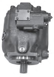

P1/PD Maintenance
23.Install bearing spacer as determined from the chart (see step 11.) Install the rear bearing on the drive shaft.
11. Install the cam bearings in the cradle area of the housing. The chamfer on the back of the bearing must face the outer wall of the housing. Use Loctite Primer Grade “T” or other suitable primer on screws and mating threads in housing. Apply Loctite #242 (use sparingly) to screw threads and install orifce screws to hold bearings in place. Torque screws to 3.4 ± 0.25 Nm (33 ± 3 in-lb).
24Confirm that compensator rotation, port plate rotation, control and bias piston location indicate same direction of rotation.

25Carefully install the assembled port block on the pump housing. Press the port block to compress the bias spring and install housing bolts. Tighten the bolts in a cross pattern to insure the port block does not get cocked on the housing. When port block is seated on the housing, torque bolts in a cross pattern as specified in chart 4.
26. Install o-ring seals and assembled compensator on side of pump housing. Pump rotation is indicated by arrow on compensator housing. Torque bolts to 5 0.25 Nm (45 3 in-lb).
12. Place thin flm of clean oil on cam bearing surfaces. Install cam in housing. For 045, the cam must be tilted to permit entry into the housing. (Figure 2) NOTE: The large pocket on the bottom surface of the cam must be on the same side as the three pressure communication holes on the main housing. Pump rotation does not affect the assembly of the cam.
13. Install the drive shaft into the pump housing. Position pump horizontally. Install the rotating group over the pump shaft. Rotate the barrel to insure that it is seated against the cam. Insure that the pump shaft is seated properly in the front bearing.
14. Confrm that compensator rotation, port plate rotation, control and bias piston location indicate same direction of rotation.
15. Carefully install the assembled port block on the pump housing. Press the port block to compress the bias spring and install housing bolts. Tighten the bolts in a cross pattern to insure the port block does not get cocked on the housing. When port block is seated on the housing, torque bolts in a cross pattern as specifed in chart 3.
16. Install o-ring seals and assembled compensator on side of pump housing. Pump rotation is indicated by arrow on compensator housing. Torque bolts to 5 ± 0.25 Nm (45 ± 3 in-lb). (See Figure 7)
Parker Hannifn Corporation Hydraulic Pump and Power Systems Division Marysville, Ohio USA
41
CCW port plates CW port plates
Dowel
CCW pump with compensator
CW pump with compensator
and quantity
port plates Mobile port plates
4 PumpHousing bolt torque 045 018, 028, 045 Pump Maintenance
3 PumpHousing bolt torque 01851 Nm (38 ft lbs) 02870 Nm (52 ft lbs) 04585 Nm (63 ft lbs)
CCW CW
compensator
note slot length
Industrial
Chart
Chart
Figure 7
Continued
PUMP ASSEMBLY PROCEDURES
Bulletin HY28-2665-02/SVC/EN
018, 028, 045 Assembly Tools
Medium Pressure Axial Piston Pumps
Parker Hannifn Corporation Hydraulic Pump and Power Systems Division Marysville, Ohio USA
Maintenance 42
133 mm (5 250 in) 31.2 mm (1 250 in) DIA. 1.5 mm x 45˚ TYP. (.06 in X 45˚) 3.0 mm RADIUS (.12 in) 18.5 mm (0.728 in) D 8.0 mm (0 3150 in) A DIA B DIA C DIA U-CUT T1 Seal installation tool A B C D (018) (028) 2.250 2.250 1.62 2.00 1.18 1.378 0.406 0.447 T3 Seal Guard A B CDE F (045 SAE) (045 ISO) (028 SAE) (028 ISO) (018 SAE) (018 ISO) +0.05 / -0.00mm (+0.002 / - 0.000 in) A B +/- 0.05mm (+/- 0.002 in) D C BLEND RADIUS & POLISH O.D. 30 F DIA BORE E DIA. Pump Model A B CDE F 018 “01”, “02”, “04” Shafts 76.20 mm 3.00 in. 50.80 mm 2.00 in. 19.05 mm 0.75 in. 15° 28.82 mm 1.135 in. 20.45 mm 0.805 in. 018 “06” Shaft 76.20 mm 3.00 in. 50.80 mm 2.00 in. 19.05 mm 0.75 in. 15° 28.82 mm 1.135 in. 16.76 mm 0.66 in. 028 / 045 “01”, “02”, “04” Shafts 76.20 mm 3.00 in. 50.80 mm 2.00 in. 19.05 mm 0.75 in. 15° 38.10 mm 1.50 in. 26.00 mm 1.024 in. 018/028/045 “08” Shaft 76.20 mm 3.00 in. 50.80 mm 2.00 in. 19.05 mm 0.75 in. 15° 28.82 mm 1.135 in. 22.50 mm 0.885 in. T1
T3 Seal Guard
P1/PD
Seal Installation Tool
Bulletin HY28-2665-02/SVC/EN
018, 028, 045 Assembly Tools
Medium Pressure Axial Piston Pumps P1/PD Maintenance
Parker Hannifn Corporation Hydraulic Pump and Power Systems Division Marysville, Ohio USA
43
mm ( in ) 08.771 00.02 )00.7( )787.0( 25.40 (1.00)
T2 Front Bearing P1/PD45 Installation Tool
mm ( in ) 29.92 ( 1.178) 89.75 ( 3.53) 50.80 ( 2.00) 19.05 ( 0.75) 38.10 ( 1.50) 101.60 ( 4.00) A B 50.80 ( 2.00) 25.40 ( 1.00) 12.7 ( 0.5)
T5 Rear Bushing Installation Tool
T5 Rear Bushing Installation Tool
Pump SizeAB 018 3.71 mm 0.146 in. 19.9 mm 0.772 in. 028 4.00 mm 0.157 in. 21.6 mm 0.85 in. 045 4.00 mm 0.157 in. 24.1 mm 0.95 in. 38 (1.5) 102 (4.0) 25 (1.0) mm (in) A B 13 (.5) 29 (1.14) 38 (1.5)
T2 Front Bearing P1/PD045 Installation Tool
Bulletin HY28-2665-02/SVC/EN
018, 028, 045 Pump Test Procedure
Medium Pressure Axial Piston Pumps
PERFORMANCE SPECIFICATIONS
*
by 2.3 lpm
TEST PROCEDURE
Parker Hannifn Corporation Hydraulic Pump and Power Systems Division Marysville, Ohio USA
P1/PD Maintenance 45
PUMP WITH PRESSURE COMPENSATOR STEP REFERENCE CONDITION 018 028 045 1 Rated Speed 1800 1800 1800 4 Output Flow at minimum pressure 32 lpm minimum 49 lpm minimum 80 lpm minimum 5 Output Flow at rated pressure of 280 bar 30 lpm minimum 47 lpm minimum 77 lpm minimum 6Case leakage at rated pressure of 280 bar 1.6 lpm 2.3 lpm 5.3 lpm 9*Case leakage when compensated at 280 bar5.7 lpm 5.7 lpm 9.5 lpm 10Input Torque when compensated at 280 bar 17.5 Nm 21.2 Nm 42 Nm 11 Output Flow when pressure reduced to 273 bar with compensator set at 280 bar 30 lpm minimum 47 lpm minimum 77 lpm minimum
When
using the A series compensators increase compensated case leakage
PUMP WITH PRESSURE COMPENSATOR STEP REFERENCE CONDITION REQUIRED VALUEMEASURED VALUE 1 Set the pump speed to 1800 RPM 1800 rpm 2 Increase pump pressure compensator adjustment to maximum. n/a 3 Record input oil temperature 43-54 ° C (110 – 130 °F) 4 Set output load pressure to minimum. Record output fow see performance chart 5 Set output load pressure to 280 ± 2 bar (4060 ± 30 psi). Record output fow see performance chart 6 Record case leakage see performance chart 7Set output pressure to 290 ± 2 bar (4200 ± 30 psi) n/a 8 Set pressure compensator to 280 ± 2 bar (4060 ± 30 psi) n/a 9 Record case leakage see performance chart 10 Record input torque see performance chart 11 Reduce output pressure to 273 ± 2 bar (3960 ± 30 psi). Record output fow see performance chart 12 Verify no external leaks No leakage permitted
060, 075, 100, 140 Pump Test Procedure
Medium Pressure Axial Piston Pumps P1/PD Maintenance
Test criteria based on hydraulic oil ISO 32 per Parker HF-0 specifications. Oil temperature: 50 C 2 C (120 F 10 F). NOTE: insure that the hydraulic system does not overheat during this test procedure. Operating speed: 0 - 2300 rpm 30 rpm. Case pressure: Maximum 14.5 psi (1 bar)
Test criteria based on hydraulic oil ISO 32 per Parker HF-0 specifications. Oil temperature: 50 C 2 C (120 F 10 F). NOTE: insure that the hydraulic system does not overheat during this test procedure. Operating speed: 0 - 2300 rpm 30 rpm. Case pressure: Maximum 14.5 psi (1 bar)
1.Mount pump on test fixture. Insure that shaft alignment is within specified tolerances.
1.Mount pump on test fixture. Insure that shaft alignment is within specified tolerances.
2.Fill case with clean oil. Connect upper drain port to reservoir with no restrictions. Insure other drain ports are properly plugged.
Test criteria based on hydraulic oil ISO 32 per Parker HF-0 specifications. Oil temperature: 50 C 2 C (120 F 10 F). NOTE: insure that the hydraulic system does not overheat during this test procedure. Operating speed: 0 - 2300 rpm 30 rpm. Case pressure: Maximum 14.5 psi (1 bar)
2.Fill case with clean oil. Connect upper drain port to reservoir with no restrictions. Insure other drain ports are properly plugged.
1.Mount pump on test fixture. Insure that shaft alignment is within specified tolerances.
3.Connect inlet and pressure lines. Insure that lines are filled with oil. Refer to circuit below. For units with “L” compensators, connect a suitable pilot line from port “X” to the pump discharge pressure line, down stream of the non-compensating flow valve.
3.Connect inlet and pressure lines. Insure that lines are filled with oil. Refer to circuit below. For units with “L” compensators, connect a suitable pilot line from port “X” to the pump discharge pressure line, down stream of the non-compensating flow valve.
2.Fill case with clean oil. Connect upper drain port to reservoir with no restrictions. Insure other drain ports are properly plugged.
4.Confirm direction of rotation for pump and drive are correct.
4.Confirm direction of rotation for pump and drive are correct.
3.Connect inlet and pressure lines. Insure that lines are filled with oil. Refer to circuit below. For units with “L” compensators, connect a suitable pilot line from port “X” to the pump discharge pressure line, down stream of the non-compensating flow valve.
5.Reduce the main compensator setting to minimum. For units with “L” compensators, advance the load sense compensator adjustment unt
il it bottoms out, and lock into position.
4.Confirm direction of rotation for pump and drive are correct.
NOTE: Items 4 and 5 are required for load
NOTE: Items 4 and 5 are required for
5.Reduce the main compensator setting to minimum. For units with “L” compensators, advance the load sense compensator adjustment unt volume stop is included, back adjustment all of the way out.
il it bottoms out, and lock into position.
6.Set maximum volume stop (if included) to full displacement. If minimum
volume stop is included, back adjustment all of the way out.
6.Set maximum volume stop (if included) to full displacement. If minimum
5.Reduce the main compensator setting to minimum. For units with “L” compensators, advance the load sense compensator adjustment unt
7.If possible, gradually increase pump speed to 1800 30 rpm with no load.
il it bottoms out, and lock into position.
6.Set maximum volume stop (if included) to full displacement. If minimum
7.If possible, gradually increase pump speed to 1800 30 rpm with no load.
8.Screw in compensator adjusting screw until it bottoms out, with no pressure on system load-relief valve.
volume stop is included, back adjustment all of the way out.
8.Screw in compensator adjusting screw until it bottoms out, with no pressure on system load-relief valve.
7.If possible, gradually increase pump speed to 1800 30 rpm with no load.
8.Screw in compensator adjusting screw until it bottoms out, with no pressure on system load-relief valve.
9.Break-in pump at times and pressures listed below. Adjust the load-relief valve to the pressure listed for the times indicated. After break-in, reduce compensator setting to 280 bar (4060 psi), and adjust system load relief to cause pump to compensate three times to verify that pump compensates on and off stroke properly.
9.Break-in pump at times and pressures listed below. Adjust the load-relief valve to the pressure listed for the times indicated. After break-in, reduce compensator setting to 280 bar (4060 psi), and adjust system load relief to cause pump to compensate three times to verify that pump compensates on and off stroke properly.
9.Break-in pump at times and pressures listed below. Adjust the load-relief valve to the pressure listed for the times indicated. After break-in, reduce compensator setting to 280 bar (4060 psi), and adjust system load relief to cause pump to compensate three times to verify that pump compensates on and off stroke properly.
Parker Hannifn Corporation Hydraulic Pump and Power Systems Division Marysville, Ohio USA Bulletin HY28-2665-02/SVC/EN
56
1. Test pump 2. Test stand prime mover 3. Pump pressure gauge 4. Non-compensating flow control 5. Load pressure gauge 6. Load relief valve 7. Safety bypass relief valve 8. Main flow meter 9. Case drain pressure gauge 10. Case drain flow meter 11. Filter
with bypass 12. Cooler
with bypass 13. Reservoir
PUMP TEST PROCEDURE TEST CIRCUIT
assembly
assembly
load sense pump test.
Time30 seconds 30 seconds 30 seconds EM 8 2 7 6 4 1 11 12 10 5 9 13 3 “X” Circuit 1 Pressure
TEST CIRCUIT
PUMP TEST PROCEDURE
1. Test pump 2. Test stand prime mover
3. Pump pressure gauge
4. Non-compensating flow control
5. Load pressure gauge
6. Load relief valve
10.
11.
12.
13.
7. Safety bypass relief valve 8. Main flow meter
9.
Case drain pressure gauge
Case drain flow meter
Filter assembly with bypass
Cooler assembly with bypass
Reservoir
sense pump test.
Time30 seconds 30 seconds 30 seconds EM 8 2 7 6 4 1 11 12 10 5 9 13 3 “X” Circuit 1 Pressure PUMP TEST PROCEDURE TEST CIRCUIT 1. Test pump 2. Test stand prime mover 3. Pump pressure gauge 4. Non-compensating flow control 5. Load pressure gauge 6. Load relief valve 7. Safety bypass relief valve 8. Main flow meter 9. Case drain pressure gauge 10. Case drain flow meter 11. Filter assembly with bypass 12. Cooler assembly with bypass 13. Reservoir NOTE: Items 4 and 5 are required for load sense pump test.
Time30 seconds 30 seconds 30 seconds EM 8 2 7 6 4 1 11 12 10 5 9 13 3 “X” Circuit 1 Pressure TEST CIRCUIT Time30 seconds30 seconds30 seconds Pressure 62-69 Bar 900-1000 psi 200-207 Bar 2900-3000 psi 269-276 Bar 3900-4000 psi
PUMP TEST PROCEDURE
Bulletin HY28-2665-02/SVC/EN
060, 075, 100, 140 Pump Test Procedure
Medium Pressure Axial Piston Pumps P1/PD Maintenance
PERFORMANCE SPECIFICATIONS
TEST PROCEDURE
Parker Hannifn Corporation Hydraulic Pump and Power Systems Division Marysville, Ohio USA
57
PUMP WITH PRESSURE COMPENSATOR STEP REFERENCE CONDITION 060 075 100 140 1 Rated Speed (RPMK 180018001800 1800 4 Output Flow at minimum pressure102 - 108 lpm132 - 135 lpm174 - 182 lpm243 - 257 lpm 5Output Flow at rated pressure of 280 bar95 lpm min.126 lpm min.165 lpm min.233 lpm min. 6Case leakage at rated pressure of 280 bar 4.5 lpm min.7.5 lpm min.9 lpm min.14 lpm min. 9* Case leakage when compensated at 280 bar 11 lpm max. 15.1 lpm max. 15.9 lpm max. 16.7 lpm max. 10 Input Torque when compensated at 280 bar 38.9 Nm max. 49.6 Nm max.67 Nm max.96.6 Nm max. 11 Output Flow when pressure reduced to 273 bar with compensator set at 280 bar 99 lpm min.126 lpm min.165 lpm min.233 lpm min.
When using the A series compensators increase compensated case leakage by 2.3 lpm
*
PUMP WITH PRESSURE COMPENSATOR STEP REFERENCE CONDITION REQUIRED VALUEMEASURED VALUE 1 Set the pump speed to 1800 RPM 1800 rpm 2 Increase pump pressure compensator adjustment to maximum. n/a 3 Record input oil temperature 43-54 ° C (110 – 130 °F) 4 Set output load pressure to minimum. Record output fow see performance chart 5 Set output load pressure to 280 ± 2 bar (4060 ± 30 psi). Record output fow see performance chart 6 Record case leakage see performance chart 7Set output pressure to 290 ± 2 bar (4200 ± 30 psi) n/a 8 Set pressure compensator to 280 ± 2 bar (4060 ± 30 psi) n/a 9 Record case leakage see performance chart 10 Record input torque see performance chart 11 Reduce output pressure to 273 ± 2 bar (3960 ± 30 psi). Record output fow see performance chart 12 Verify no external leaks No leakage permitted
Bulletin HY28-2665-02/SVC/EN
060, 075, 100, 140 Pump Test Procedure
Medium Pressure Axial Piston Pumps
PERFORMANCE SPECIFICATIONS
TEST PROCEDURE
1Set the pump speed to 1800 RPM
2Record
3A Set output load prssure to 50 ± 2 bar (725 ± 30 psi)
3B Adjust throttle valve and adjust differential setting until pressure at pump outlet is 20 ± 2 bar (290 ± 30 psi) higher than the load pressure gage
4 Adjust throttle valve to required fow raqte. Adjust output load presure valve if necessary to maintain 50 ± 2 bar (725 ± 30 psi)
5 Increase the output pressure to 260 ± 2 bar (3770 ±30 psi). Verify that the fow remains within specifed limits.
6 Lock the load sense adjustment screw. Confrm differential pressure at 20 ± 2 bar (290 ± 30 psi).
7Verify no external leaks
See performance chart
See performance chart
No leakage permitted
Parker Hannifn Corporation Hydraulic Pump and Power Systems Division Marysville, Ohio USA
58
P1/PD Maintenance
PUMP WITH LOAD SENSE COMPENSATOR STEP REFERENCE CONDITION 060 075 100 140 1Rated Speed (RPM) 180018001800 1800
Load sense output fow setting at 50 ± 2 bar (725 ±30 psi) 60-63 lpm77-79 lpm103 - 105 lpm145-147 lpm
Allowable fow variation from 50 to 260 ± 2 bar (725
3770 ± 30 psi) 56-66 lpm73-83 lpm99-109 lpm136-156 lpm
4
5
to
LOAD SENSE COMPENSATOR STEP REFERENCE CONDITION REQUIRED VALUEMEASURED VALUE
PUMP WITH
1800
rpm
input oil temperature 43-54 ° C (110 – 130 °F)
n/a n/a
n/a n/a
n/a n/a
Bulletin HY28-2665-02/SVC/EN
Conversions & Formulas CONVERSION
FLUID
Medium Pressure Axial Piston Pumps P1/PD Maintenance
Parker Hannifn Corporation Hydraulic Pump and Power Systems Division Marysville, Ohio USA
59
FACTORS DEFINITION & UNIT displacement in3/rev x 16.387 = cm3/rev cm3/rev x 0.06102 = in3/rev fow gpm x 3.78 = L/min L/min x 0.2642 = gpm power hp x 0.7457 = kW kW x 1.341 = hp torque lb-ft x 1.3567 = Nm Nm x 0.7376 = lb-ft pressure lbs/in2 (psi) x 0.06895 = bar bar x 14.50 = lbs/in2 (psi) lbs/in2 (psi) x 6.895 = kPa kPa x 0.1450 = lbs/in2 (psi) weight lb x 0.4536 = kg kg x 2.205 = lbs force lb x 4.448 = N N x 0.2248 = lbs volume in3 x 16.387 = cm3 cm3 x 0.06102 = in3 area in2 x 6.452 = cm2 cm2 x 0.1550 = in2 length in x 25.4 = mm mm x 0.03937 = in temperature degree F-32 = °C 1.8 x C+32 = °F 1.8 viscosity cSt x 1.0 = mm2/sec mm2/sec x 1.0 = cSt SSU = cSt x 4.25 + 14 20 cSt = 99 SSU
Pump input torque lbs. in. pressure(psi) x displacement (in3/rev) 2� x mech. eff. Pump input power hp rpm x (in3/rev) x (psi) 395934 x overall eff. Pump output fow U.S. gpm rpm x (in3/rev) x volumetric eff. 231 Fluid motor speed rpm 231 x fow rate(U.S. gpm) x volumetric eff. displacement (in3/rev) Fluid motor torque lbs. in. pressure(psi) x displacement (in3/rev) x mech. eff. 2� Fluid motor power hp rpm x (in3/rev) x (psi) x overall eff. 395934 (metric) Pump input torque Nm pressure(bar) x displacement (cm3/rev) 20� x mech. eff. Pump input power kW rpm x (cm3/rev) x (bar) 600000 x overall eff. Pump output fow Lpm rpm x (cm3/rev) x volumetric eff. 1000 Fluid motor speed rpm(min-1 ) (tr/mn) 1000 x fow rate (Lpm) x volumetric eff. displacement (cm3/rev) Fluid motor torque Nm pressure(bar) x displacement (cm3/rev) x mech. eff. 20� Fluid motor power kW rpm x (cm3/rev) x (bar) x overall eff. 600000
POWER FORMULAS
Bulletin HY28-2665-02/SVC/EN
Notes
Medium Pressure Axial Piston Pumps
P1/PD Maintenance
Parker Hannifn Corporation Hydraulic Pump and Power Systems Division Marysville, Ohio USA
60
Bulletin HY28-2665-02/SVC/EN
Content Index
Jan 1st, 2014 - October 2013 service manual update log:
Update item #9 and 44 on 028 parts list
Updated item #22 on 045 parts list
Medium Pressure Axial Piston Pumps P1/PD Maintenance
Update item #22, 35 and 37 on 060,075,100,140 parts list
Added part # 106 and 107 to RDEC parts list
Added 018 through drive couplings
Added 028 BB through drive coupling
For L0, L1, L2 and L3 compensator moved note from item number 6 to item number 4
Updated exploded view on C0 and C1 compensator
Updated part number on CCW AL control
Added additional information to port adapters on A series compensators
Updated case fow readings when compensated on all pumps.
Added note on case fow readings when using A series compensators.
Feb 19th, 2015 - P1-PD140 model code through drive coupling descriptions corrected
Updated moment of inertia data for through drive on 18cc unit
Port plates for P1/PD 100 unit have been updated
Volume stop kit numbers have been updated. New table layout.
Load sense controller part numbers updated.
Pressure compensator part numbers updated.
Parker Hannifn Corporation
Hydraulic Pump and Power Systems Division Marysville, Ohio USA
61
Bulletin HY28-2665-02/SVC/EN
Notes
Medium Pressure Axial Piston Pumps
P1/PD Maintenance
Parker Hannifn Corporation Hydraulic Pump and Power Systems Division Marysville, Ohio USA
62
Bulletin HY28-2665-02/SVC/EN
Offer of Sale
Medium Pressure Axial Piston Pumps P1/PD Maintenance
The items described in this document and other documents and descriptions provided by Parker Hannifn Corporation, Hydraulics Group, and its authorized distributors (“Seller”) are hereby offered for sale at prices to be established by Seller. This offer and its acceptance by any customer (“Buyer”) shall be governed by all of the following Terms and Conditions. Buyer’s order for any item described in its document, when communicated to Seller verbally, or in writing, shall constitute acceptance of this offer. All goods or work described will be referred to as “Products”.
1. Terms and Conditions. Seller’s willingness to offer Products, or accept an order for Products, to or from Buyer is expressly conditioned on Buyer’s assent to these Terms and Conditions and to the terms and conditions found on-line at www.parker.com/saleterms/. Seller objects to any contrary or additional term or condition of Buyer’s order or any other document issued by Buyer.
2. Price Adjustments; Payments. Prices stated on the reverse side or preceding pages of this document are valid for 30 days. After 30 days, Seller may change prices to refect any increase in its costs resulting from state, federal or local legislation, price increases from its suppliers, or any change in the rate, charge, or classifcation of any carrier. The prices stated on the reverse or preceding pages of this document do not include any sales, use, or other taxes unless so stated specifcally. Unless otherwise specifed by Seller, all prices are F.O.B. Seller’s facility, and payment is due 30 days from the date of invoice. After 30 days, Buyer shall pay interest on any unpaid invoices at the rate of 1.5% per month or the maximum allowable rate under applicable law.
3. Delivery Dates; Title and Risk; Shipment. All delivery dates are approximate and Seller shall not be responsible for any damages resulting from any delay. Regardless of the manner of shipment, title to any products and risk of loss or damage shall pass to Buyer upon tender to the carrier at Seller’s facility (i.e., when it’s on the truck, it’s yours). Unless otherwise stated, Seller may exercise its judgment in choosing the carrier and means of delivery. No deferment of shipment at Buyers’ request beyond the respective dates indicated will be made except on terms that will indemnify, defend and hold Seller harmless against all loss and additional expense. Buyer shall be responsible for any additional shipping charges incurred by Seller due to Buyer’s changes in shipping, product specifcations or in accordance with Section 13, herein.
4. Warranty. Seller warrants that the Products sold hereunder shall be free from defects in material or workmanship for a period of eighteen months from the date of delivery to Buyer. The prices charged for Seller’s products are based upon the exclusive limited warranty stated above, and upon the following disclaimer: DISCLAIMER OF WARRANTY: THIS WARRANTY COMPRISES THE SOLE AND ENTIRE WARRANTY PERTAINING TO PRODUCTS PROVIDED HEREUNDER. SELLER DISCLAIMS ALL OTHER WARRANTIES, EXPRESS AND IMPLIED, INCLUDING MERCHANTABILITY AND FITNESS FOR A PARTICULAR PURPOSE.
5. Claims; Commencement of Actions. Buyer shall promptly inspect all Products upon delivery. No claims for shortages will be allowed unless reported to the Seller within 10 days of delivery. No other claims against Seller will be allowed unless asserted in writing within 60 days after delivery or, in the case of an alleged breach of warranty, within 30 days after the date within the warranty period on which the defect is or should have been discovered by Buyer. Any action based upon breach of this agreement or upon any other claim arising out of this sale (other than an action by Seller for any amount due to Seller from Buyer) must be commenced within thirteen months from the date of tender of delivery by Seller or, for a cause of action based upon an alleged breach of warranty, within thirteen months from the date within the warranty period on which the defect is or should have been discovered by Buyer.
6. LIMITATION OF LIABILITY. UPON NOTIFICATION, SELLER WILL, AT ITS OPTION, REPAIR OR REPLACE A DEFECTIVE PRODUCT, OR REFUND THE PURCHASE PRICE. IN NO EVENT SHALL SELLER BE LIABLE TO BUYER FOR ANY SPECIAL, INDIRECT, INCIDENTAL OR CONSEQUENTIAL DAMAGES ARISING OUT OF, OR AS THE RESULT OF, THE SALE, DELIVERY, NON-DELIVERY, SERVICING, USE OR LOSS OF USE OF THE PRODUCTS OR ANY PART THEREOF, OR FOR ANY CHARGES OR EXPENSES OF ANY NATURE INCURRED WITHOUT SELLER’S WRITTEN CONSENT, EVEN IF SELLER HAS BEEN NEGLIGENT, WHETHER IN CONTRACT, TORT OR OTHER LEGAL THEORY. IN NO EVENT SHALL SELLER’S LIABILITY UNDER ANY CLAIM MADE BY BUYER EXCEED THE PURCHASE PRICE OF THE PRODUCTS.
7. Contingencies. Seller shall not be liable for any default or delay in performance if caused by circumstances beyond the reasonable control of Seller.
8. User Responsibility. The user, through its own analysis and testing, is solely responsible for making the fnal selection of the system and Product and assuring that all performance, endurance, maintenance, safety and warning requirements of the application are met. The user must analyze all aspects of the application and follow applicable industry standards and Product information. If Seller provides Product or system options, the user is responsible for determining that such data and specifcations are suitable and suffcient for all applications and reasonably foreseeable uses of the Products or systems.
9. Loss to Buyer’s Property. Any designs, tools, patterns, materials, drawings, confdential information or equipment furnished by Buyer or any other items which become Buyer’s property, may be considered obsolete and may be destroyed by Seller after two consecutive years have elapsed without Buyer placing an order for the items which are manufactured using such property. Seller shall not be responsible for any loss or damage to such property while it is in Seller’s possession or control.
10. Special Tooling. A tooling charge may be imposed for any special tooling, including without limitation, dies, fxtures, molds and patterns, acquired to manufacture Products. Such special tooling shall be and remain Seller’s property notwithstanding payment of any charges by Buyer. In no event will Buyer acquire any interest in apparatus belonging to Seller which is utilized in the manufacture of the Products, even if such apparatus has been specially converted or adapted for such manufacture and notwithstanding any charges paid by Buyer. Unless otherwise agreed, Seller shall have the right to alter, discard or
Parker Hannifn Corporation
Hydraulic Pump and Power Systems Division
Marysville, Ohio USA
otherwise dispose of any special tooling or other property in its sole discretion at any time.
11. Buyer’s Obligation; Rights of Seller. To secure payment of all sums due or otherwise, Seller shall retain a security interest in the goods delivered and this agreement shall be deemed a Security Agreement under the Uniform Commercial Code. Buyer authorizes Seller as its attorney to execute and fle on Buyer’s behalf all documents Seller deems necessary to perfect its security interest. Seller shall have a security interest in, and lien upon, any property of Buyer in Seller’s possession as security for the payment of any amounts owed to Seller by Buyer.
12. Improper Use and Indemnity. Buyer shall indemnify, defend, and hold Seller harmless from any claim, liability, damages, lawsuits, and costs (including attorney fees), whether for personal injury, property damage, patent, trademark or copyright infringement or any other claim, brought by or incurred by Buyer, Buyer’s employees, or any other person, arising out of: (a) improper selection, improper application or other misuse of Products purchased by Buyer from Seller; (b) any act or omission, negligent or otherwise, of Buyer; (c) Seller’s use of patterns, plans, drawings, or specifcations furnished by Buyer to manufacture Product; or (d) Buyer’s failure to comply with these terms and conditions. Seller shall not indemnify Buyer under any circumstance except as otherwise provided.
13. Cancellations and Changes. Orders shall not be subject to cancellation or change by Buyer for any reason, except with Seller’s written consent and upon terms that will indemnify, defend and hold Seller harmless against all direct, incidental and consequential loss or damage. Seller may change product features, specifcations, designs and availability with notice to Buyer.
14. Limitation on Assignment. Buyer may not assign its rights or obligations under this agreement without the prior written consent of Seller.
15. Entire Agreement. This agreement contains the entire agreement between the Buyer and Seller and constitutes the fnal, complete and exclusive expression of the terms of the agreement. All prior or contemporaneous written or oral agreements or negotiations with respect to the subject matter are herein merged.
16. Waiver and Severability. Failure to enforce any provision of this agreement will not waive that provision nor will any such failure prejudice Seller’s right to enforce that provision in the future. Invalidation of any provision of this agreement by legislation or other rule of law shall not invalidate any other provision herein. The remaining provisions of this agreement will remain in full force and effect.
17. Termination. This agreement may be terminated by Seller for any reason and at any time by giving Buyer thirty (30) days written notice of termination. In addition, Seller may by written notice immediately terminate this agreement for the following: (a) Buyer commits a breach of any provision of this agreement (b) the appointment of a trustee, receiver or custodian for all or any part of Buyer’s property (c) the fling of a petition for relief in bankruptcy of the other Party on its own behalf, or by a third party (d) an assignment for the beneft of creditors, or (e) the dissolution or liquidation of the Buyer.
18. Governing Law. This agreement and the sale and delivery of all Products hereunder shall be deemed to have taken place in and shall be governed and construed in accordance with the laws of the State of Ohio, as applicable to contracts executed and wholly performed therein and without regard to conficts of laws principles. Buyer irrevocably agrees and consents to the exclusive jurisdiction and venue of the courts of Cuyahoga County, Ohio with respect to any dispute, controversy or claim arising out of or relating to this agreement. Disputes between the parties shall not be settled by arbitration unless, after a dispute has arisen, both parties expressly agree in writing to arbitrate the dispute. 19. Indemnity for Infringement of Intellectual Property Rights. Seller shall have no liability for infringement of any patents, trademarks, copyrights, trade dress, trade secrets or similar rights except as provided in this Section. Seller will defend and indemnify Buyer against allegations of infringement of U.S. patents, U.S. trademarks, copyrights, trade dress and trade secrets (“Intellectual Property Rights”). Seller will defend at its expense and will pay the cost of any settlement or damages awarded in an action brought against Buyer based on an allegation that a Product sold pursuant to this Agreement infringes the Intellectual Property Rights of a third party. Seller’s obligation to defend and indemnify Buyer is contingent on Buyer notifying Seller within ten (10) days after Buyer becomes aware of such allegations of infringement, and Seller having sole control over the defense of any allegations or actions including all negotiations for settlement or compromise. If a Product is subject to a claim that it infringes the Intellectual Property Rights of a third party, Seller may, at its sole expense and option, procure for Buyer the right to continue using the Product, replace or modify the Product so as to make it noninfringing, or offer to accept return of the Product and return the purchase price less a reasonable allowance for depreciation. Notwithstanding the foregoing, Seller shall have no liability for claims of infringement based on information provided by Buyer, or directed to Products delivered hereunder for which the designs are specifed in whole or part by Buyer, or infringements resulting from the modifcation, combination or use in a system of any Product sold hereunder. The foregoing provisions of this Section shall constitute Seller’s sole and exclusive liability and Buyer’s sole and exclusive remedy for infringement of Intellectual Property Rights. 20. Taxes. Unless otherwise indicated, all prices and charges are exclusive of excise, sales, use, property, occupational or like taxes which may be imposed by any taxing authority upon the manufacture, sale or delivery of Products.
21. Equal Opportunity Clause. For the performance of government contracts and where dollar value of the Products exceed $10,000, the equal employment opportunity clauses in Executive Order 11246, VEVRAA, and 41 C.F.R. §§ 60-1.4(a), 60-741.5(a), and 60-250.4, are hereby incorporated.
63
Parker Hannifn Corporation Hydraulic Pump and Power Systems Division 14249 Industrial Parkway Marysville, OH 43040 USA phone 937 644 4435 fax 937 642 3639 www.parker.com/hps Bulletin HY28-2665-02/SVC/EN Effective: 02/2015
© 2015 Parker Hannifn Corporation, all rights reserved
