BOVA20 Series Condensing Unit
2-3-4-5 Ton Capacity | R454B


Installation and Operating Instructions Bosch IDS Premium Connected
BTC 762003301 A / 04.2024
Installation and Operating Instructions
Premium
BOVA20 Series Condensing Unit - BTC 762003301 A (04.2024) 2 |
Bosch IDS
Connected
Installation and Operating Instructions Bosch IDS Premium Connected BOVA20 Series Condensing Unit - BTC 762003301 A (04.2024) | 3 Table of Contents 1 Key to Symbols and Safety Instructions 4 1.1 Key to Symbols 4 1.2 Explanation of Symbols Displayed on the Unit 4 1.3 Safety 4 1.3.1 Gateway Related Warnings 10 2 Bosch EasyAir Mobile App 11 3 Unit Location Considerations 11 3.1 Unit Dimensions 11 3.2 Refrigerant Piping Limits 12 3.3 Location Restrictions 13 3.4 Refrigerant Charge and Room Area Limitations 14 3.4.1 The Room Area Calculation Requirements 15 3.4.2 The Allowed Maximum Refrigerant Charge and Required Minimum Room Area 16 4 Unit Preparation 17 4.1 Prepare the Unit for Installation 17 5 Setting the Unit 17 5.1 Pad Installation 17 5.2 Mounting Antenna 18 6 Refrigerant Line Considerations 19 6.1 Refrigerant Line and Service Valve Connection Sizes 19 6.2 Required Refrigerant Line Length 19 6.3 Refrigerant Line Insulation 19 6.4 Reuse Existing Refrigerant Lines 19 7 Refrigerant Line Routing 19 7.1 Precautions 19 8 Refrigerant Line Connection 21 9 Refrigerant Line Brazing 22 9.1 Braze The Refrigerant Lines 22 10 Refrigerant Line Leak Check 23 10.1 Check For Leaks 23 11 Evacuation 24 11.1 Evacuate the Refrigerant Lines and Indoor Coil 24 12 Service Valves 24 12.1 Open the Service Valves 24 13 Electrical - Low Voltage 25 13.1 Low Voltage Maximum Wire Length 25 13.2 Low Voltage Hook-Up Diagrams 25 13.3 Thermostat Wiring 25 13.3.1 Non-Communicating Set Up 26 13.3.2 Communicating Set Up 30 14 Electrical - High Voltage 37 14.1 High Voltage Power Supply 37 14.2 High Voltage Disconnect Switch 37 14.3 High Voltage Ground 37 15 Start Up 38 15.1 System Start Up 38 16 System Charge Adjustment 40 16.1 Charging: Weigh-In Method 40 16.2 Subcooling Charging And Refrigerant Adjustment In Cooling (Above 55°F Outdoor Temp.) 40 16.3 Record the Refrigerant Charge Amount 42 17 System Operation and Troubleshooting 43 17.1 Control Logic Description 43 17.2 Sensors (Thermistors/Pressure Transducer) 43 17.3 Pressure Equalizer Valve (PEV) 43 17.4 Defrost Description 43 17.5 Compressor Crankcase Heater Description 44 17.6 Reversing Valve Operation 44 17.7 Protection Functions 44 17.8 Fault Code Table 45 17.9 System Protection Status Codes 46 17.10 Parameter Point Check Table 47 17.11 Control Board Overviews 48 17.12 Error Code Troubleshooting 50 17.13 Temperature and Resistance Relationship Tables (for Sensors) 63 17.14 Temperature and Resistance Relationship Tables (for T5 & Tf Sensors) 64 18 Wiring Diagram 65 19 IDS2.1 Gateway Functionality 66 20 Care and Maintenance 67 20.1 Cleaning Precautions 67 20.2 Maintenance – Pre-Season Inspection 67 21 Disposal 68
1 Key to Symbols and Safety Instructions
1.1 Key to Symbols
Warnings
In warnings, signal words at the beginning of a warning are used to indicate the type and seriousness of the ensuing risk if measures for minimizing danger are not taken.
The following keywords are defined and can be used in this document:
DANGER
DANGER indicates a hazardous situation which, if not avoided, will result in death or serious injury.
WARNING
WARNING indicates a hazardous situation which, if not avoided, could result in death or serious injury.
CAUTION
CAUTION indicates a hazardous situation which, if not avoided, could result in minor to moderate injury.
NOTICE
NOTICE is used to address practices not related to personal injury.
Important information
The info symbol indicates important information where there is no risk to people or property.
1.2 Explanation of Symbols Displayed on the Unit
Symbol Description
WARNING
WARNING
This symbol shows that this appliance used a flammable refrigerant. If the refrigerant is leaked and exposed to an external ignition source, there is a risk of fire.
This symbol shows that appliance shall be installed, operated and stored in a room with a floor area not less than the minimum room area.
CAUTION This symbol shows that the operation manual should be read carefully.
CAUTION This symbol shows that a service personnel should be handling this equipment with reference to the installation manual.
CAUTION This symbol shows that information is available such as the operating manual or installation manual.
CAUTION
This symbol shows that when addition of charge is required by the manufacturer installation instructions for completing the REFRIGERATING SYSTEM. Recorded the resulting total REFRIGERANT CHARGE for each REFRIGERATING SYSTEM.
Table 1
1.3 Safety
Please read safety precautions before installation
WARNING
Electrical hazard 380 Volts DC!
Failure to follow this warning could result in property damage, severe personal injury, or death.
WAIT FIVE (5) MINUTES after disconnecting power prior to touching electrical components as they may hold a dangerous charge of 380 VDC,then verify DC Voltage is less than 42VDC at inverter TEST POINTS P-N.
This document is customer property and is to remain with this unit. Please return to service information pack upon completion of work.
These instructions do not cover all variations in systems or provide for every possible contingency to be met in connection with the installation.
Should further information be desired or should particular problems arise which are not covered sufficiently for the purchaser’s purposes, the matter should be referred to your installing dealer or local distributor.
Installation and Operating Instructions Bosch IDS Premium Connected BOVA20 Series Condensing Unit - BTC 762003301 A (04.2024) 4 |
≥ A m2
kg kg kg
The manufacturer recommends installing only approved matched indoor and outdoor systems. All of the manufacturer’s split systems are AHRI rated only with TXV indoor systems. Some of the benefits of installing approved matched indoor and outdoor split systems are maximum efficiency, optimum performance and the best overall system reliability.
This document contains a wiring diagram and service information. This is customer property and is to remain with this unit. Please return to service information pack upon completion of work. installation.
WARNING
Personal injury, product damage!
This information is intended for use by individuals possessing adequate backgrounds of electrical and mechanical experience. Any attempt to repair a central air conditioning product may result in personal injury and/or property damage.
WARNING
Hazardous voltage!
Failure to follow this warning could result in property damage, severe personal injury, or death.
Disconnect all electric power, Including remote disconnects before servicing. Follow proper lockout/tagout procedures to ensure the power cannot be inadvertently energized.
WARNING
Refrigerant oil!
Any attempt to repair a central air conditioning product may result in property damage, severe personal injury, or death. These units use R454b refrigerant. Use only R454b approved service equipment. All R454b systems with variable speed compressors use a POE oil (VG75 or equivalent )that readily absorbs moisture from the atmosphere. To limit this ‘hygroscopic“ action, the system should remain sealed whenever possible. If a system has been open to the atmosphere for more than 4 hours, the compressor oil must be replaced. Never break a vacuum with air and always change the driers when opening the system for component replacement.
WARNING
May cause minor to severe burning. Failure to follow this Caution could result in property damage or personal injury.
Do not touch high temperature components such as the compressor.
WARNING Contains refrigerant!
Failure to follow proper procedures can result in personal illness or injury or severe equipment damage.System contains oil and refrigerant under high pressure. Recover refrigerant to relieve pressure before opening system. f Flammable refrigerant used.
WARNING Contains lead!
This product can expose you to chemicals including Lead and Lead components, which are known to the State of California to cause cancer and birth defects or other reproductive harm. For more information go to www. P65Warnings.ca.gov.
CAUTION
Grounding required!
Failure to inspect or use proper service tools may result in equipment damage or personal injury. Reconnect all grounding devices. All parts of this product that are capable of conducting electrical current are grounded. If grounding wires, screws, straps, clips, nuts, or washers used to complete a path to ground are removed for service, they must be returned to their original position and properly fastened.
WARNING
Service valves!
Failure to follow this warning will result in abrupt release of system charge and may result in personal injury and/ or property damage. Extreme caution should be exercised when opening the Liquid Line Service valve. Turn valve stem counterclockwise only until the stem contacts the rolled edge.
WARNING
Brazing required!
Failure to inspect lines or use proper service tools may result in equipment damage or personal injury. If using existing refrigerant lines make certain that all joints are brazed, not soldered.
If refrigerant gas leaks during installation, ventilate the area immediately. Comply with national gas regulations.
WARNING
High current leakage!
Grounding is required before connecting electrical supply. Failure to follow this warning could result in property damage, severe personal injury, or death.
WARNING
Risk of fire!
Mildly flammable refrigerant used.
Follow handling instructions carefully in compliance with national regulations.
DANGER
Fire, explosion!
Store in a well ventilated room without continuously operating flames or other potential ignition.
WARNING
Risk of electric shock!
Can cause injury or death.Disconnect all remote electric power supplies before servicing.
Installation and Operating Instructions Bosch IDS Premium Connected BOVA20 Series Condensing Unit - BTC 762003301 A (04.2024) | 5
Hot surface!
WARNING
Risk of fire!
Flammable refrigerant used. To be repaired only by trained service personnel. Do not puncture refrigerant tubing.
Dispose of properly in accordance with federal or local regulations. Flammable refrigerant used.
Flammable refrigerant used. Consult repair manual/owner’s guide before attempting to service this product. All safety precautions must be followed.
Auxiliary devices which may be ignition sources shall not be installed in the ductwork, other than auxiliary devices listed for use with the specific appliance. See instructions.
WARNING
Personal injury!
This appliance is not intended for use by persons (including children) with reduced physical, sensory or mental capabilities, or persons who lack experience andknowledge, unless they are supervised or have been given instructions concerning the use of the appliance by a person responsible for their safety. Children should be supervised to ensure that they do not play with the appliance.
Any person who is involved with working on or opening a refrigerant circuit should hold a current valid certificate from an industry-accredited assessment authority,which authorizes their competence to handle refrigerants safely in accordance with an industry recognized assessment credential.
Servicing shall only be performed as recommended by the equipment manufacturer.
Maintenance and repair requiring the assistance of other skilled personnel shall be carried out under the supervision of a person competent in the use of flammable refrigerants.
Prior to beginning work on systems containing flammable refrigerants, safety checks are necessary to minimize the risk of ignition.
WARNING
Flammable refrigerant!
Do not use means to accelerate the defrosting process or to clean, other than those recommended by the manufacturer.
The appliance shall be stored in a room that does not have continuously operating ignition sources (for example: open flames, an operating gas appliance or an operating electric heater).
Do not pierce or burn the unit.
Be aware that refrigerants may not contain an odour.
WARNING
Safe handling of flammable refrigerant!
Be sure the air conditioner is grounded.In order to avoid electric shock, make sure that the unit is grounded and that the earth wire is not connected to a gas or water pipe, lightning conductor or telephone earth wire.
Do not operate the air conditioner with a wet hands.An electric shock may happen.
Do not operate the air conditioner when using a room fumigation - type insecticide. Failure to observe this precaution could cause the chemicals to become deposited in the unit,which could endanger the health of those who are hypersensitive to chemicals.
To avoid oxygen deficiency, ventilate the room sufficiently if equipment with a burner is used together with the air conditioner.
Arrange the drain hose to ensure smooth drainage. Incomplete drainage may cause wetting of thebuilding, furniture, etc.
Never touch the internal parts of the controller.Do not remove the front panel. Some parts inside are dangerous to touch, and machine troubles may occur.
Attention is drawn to the fact that additional transportation regulations may exist with respect to equipment containing flammable gas. The maximum number of pieces of equipment or the configuration of the equipment permitted to be transported together will be determined by the applicable transport regulations.
Signs for similar appliances used in a work area are generally addressed by local regulations and give the minimum requirements for the provision of safety and/or health signs for a work location.
Storage package protection should be constructed such a way that mechanical damage to the equipment inside the package will not cause a leak of the REFRIGERANT CHARGE.
The maximum number of pieces of equipment permitted to be stored together will be determined by local regulations.
Do not place appliances which produce open flame in places exposed to the air flow from the unit or under the indoor unit. It may cause incomplete combustion or deformation of the unit due to the heat.
Do not install the air conditioner in a location where flammable gas may leak out. If the gas leaks out and stays around the airconditioner, a fire may break out.
WARNING
Flammable refrigerant!
The appliance can uses R454B refrigerant.
NOTICE
Indoor unit required!
The indoor units must be matched with R-454B TXV. The model of R-454B TXV can be changed according to the system capacity.
Installation and Operating Instructions Bosch IDS Premium Connected BOVA20 Series Condensing Unit - BTC 762003301 A (04.2024) 6 |
WARNING
Personal Injury, flammable refrigerant!
When repairing the refrigerating system, comply with the following precautions prior to conducting work on the system:
• Work shall be undertaken according to controlled procedures to minimize the risk of the presence of flammable gases or vapors while the work is being performed.
• All maintenance staff and others working in the local area shall be instructed on the nature of work being carried out. Work in confined spaces shall be avoided.
• The area shall be checked with an appropriate refrigerant detector prior to and during work, to ensure the technician is aware of potentially toxic or flammable environment. Ensure that the leak detection equipment being used is suitable for use with all applicable refrigerants, i.e., non-sparking, adequately sealed or intrinsically safe.
• If any hot work is to be conducted on the refrigerating equipment or any associated parts, appropriate fire extinguishing equipment shall be available and easily accessible. Have a dry powder or CO2 fire extinguisher adjacent to the charging area.
• When carrying out work in relation to a refrigerating system that involves exposing any pipe work, no sources of ignition shall be used in such a manner that it may lead to the risk of fire or explosion. All possible ignition sources, including cigarette smoking, should be kept sufficiently far away from the site of installation, repair, or removal and disposal of the unit, during which refrigerant can possibly be released into the surrounding space. Prior to beginning work, the area around the equipment is to be surveyed to make sure that there are no flammable hazards or ignition risks. “No Smoking” signs shall be clearly displayed.
WARNING
Personal Injury, flammable refrigerant!
Ensure that the area is in the open or that it is adequately ventilated before opening the system or conducting any hot work. A degree of ventilation shall continue during the period that the work is carried out. The ventilation should safely disperse any released refrigerant and preferably expel it externally into the surroundings.
Where electrical components are being changed, they shall be fit according to their purpose and to the correct specification. At all times the manufacturer’s maintenance and service guidelines shall be followed. If in doubt, consult the manufacturer’s technical department for assistance. The following checks shall be applied to installations using flammable refrigerants:
• The actual refrigerant charge is in accordance with the room size within which the refrigerant containing parts are installed.
• The ventilation machinery and outlets are operating adequately and are not obstructed.
• If an indirect refrigerating circuit is being used, the secondary circuit shall be checked for the presence of refrigerant.
• Equipment marking must remain visible and legible. Markings and signs that are illegible shall be corrected.
WARNING
Personal Injury, flammable refrigerant!
Refrigerating pipe or components are installed in a position where they are unlikely to be exposed to any substances which may corrode refrigerant containing components, unless the components are constructed of materials that are inherently resistant to corrosion or are suitably protected against corrosion.
Repair and maintenance of electrical components shall include initial safety checks and component inspection procedures. If a fault exists that could compromise safety, then no electrical supply shall be connected to the circuit until the fault has been dealt with.
• That capacitors are discharged: this shall be done in a safe manner to avoid the possibility of sparking.
• That no live electrical components and wiring are exposed while charging, recovering or purging the system.
• That there is continuity of grounding.
WARNING
Flammable refrigerant!
Sealed electrical components shall be replaced.
Intrinsically safe components must be replaced.
Check that cabling will not be subject to wear, corrosion, excessive pressure, vibration, sharp edges or any other adverse environmental effects. The check shall also take into account the effects of aging or continual vibration from sources such as compressors or fans.
Under no circumstances shall potential sources of ignition be used while searching for or detection of refrigerant leaks. A halide torch (or any other detector using a naked flame) shall not be used.
Electronic leak detectors may be used to detect refrigerant leaks but, in the case of flammable refrigerants, the sensitivity may not be adequate, or may need recalibration. (Detection equipment shall be calibrated in a refrigerant-free area.)
Ensure that the detector is not a potential source of ignition and is suitable for the refrigerant used. Leak detection equipment shall be set at a percentage of the LFL of the refrigerant and shall be calibrated for the refrigerant employed, and the appropriate percentage of gas (25 % maximum) is confirmed.
If a leak is suspected, all naked flames shall be removed/extinguished. If a leakage of refrigerant which requires brazing is found, all of the refrigerant shall be recovered from the system, or isolated (by means of shut off valves) in a part of the system remote from the leak.
Leak detection fluids are also suitable for use with most refrigerants but the use of detergents containing chlorine shall be avoided as the chlorine may react with the refrigerant and corrode the copper pipe-work.
Examples of leak detection fluids are:
• bubble method,
• fluorescent method agents.
Installation and Operating Instructions Bosch IDS Premium Connected BOVA20 Series Condensing Unit - BTC 762003301 A (04.2024) | 7
Flammable refrigerant!
When breaking into the refrigerant circuit to make repairs or for any other purpose conventional procedures shall be used. However, for flammable refrigerants it is important that best practice be followed, since flammability is a consideration. The following procedure shall be adhered to:
• safely remove refrigerant following local and national regulations.
• evacuate.
• purge the circuit with inert gas.
• evacuate.
• continuously flush or purge with inert gas when using flame to open circuit, and.
• open the circuit.
The refrigerant charge shall be recovered into the correct recovery cylinders if venting is not allowed by local and national codes. For appliances containing flammable refrigerants, the system shall be purged with oxygen-free nitrogen to render the appliance safe for flammable refrigerants. This process might need to be repeated several times. Compressed air or oxygen shall not be used for purging refrigerant systems.
For appliances containing flammable refrigerants, refrigerants purging shall be achieved by breaking the vacuum in the system with oxygen-free nitrogen and continuing to fill until the working pressure is achieved, then venting to atmosphere, and finally pulling down to a vacuum. This process shall be repeated until no refrigerant is within the system. When the final oxygen-free nitrogen charge is used, the system shall be vented down to atmospheric pressure to enable work to take place.
The outlet for the vacuum pump shall not be close to any potential ignition sources, and ventilation shall be available.
Ensure that contamination of different refrigerants does not occur when using charging equipment. Hoses or lines shall be as short as possible to minimize the amount of refrigerant they contain.
Cylinders shall be kept upright. Ensure that the refrigeration system is grounded prior to charging the system with refrigerant.
Label the system when charging is complete (if it is not already labeled). Take extreme care not to overfill the refrigeration system.
Flammable refrigerant!
Prior to recharging the system, it shall be pressure-tested with the appropriate purging gas. The system shall be leak-tested on completion of charging but prior to commissioning. A follow up leak test shall be carried out prior to leaving the site.
Before carrying out this procedure, it is essential that the technician is completely familiar with the equipment and all its detail. It is recommended that all refrigerants are recovered safely. Prior to the task being carried out, an oil and refrigerant sample shall be taken in case analysis is required prior to re-use of reclaimed refrigerant. It is essential that electrical power is available before the task is commenced.
a. Become familiar with the equipment and its operation.
b. Isolate system electrically.
c. Before attempting the procedure ensure that:
• mechanical handling equipment is available, if required, for handling refrigerant cylinders.
• all personal protective equipment is available and being used correctly.
• the recovery process is supervised at all times by a competent person.
• recovery equipment and cylinders conform to the appropriate standards.
d. Pump down refrigerant system, if possible.
e. If a vacuum is not possible, make a manifold so that refrigerant can be removed from various parts of the system.
f. Make sure that the cylinder is situated on the scales before recovery takes place.
g. Start the recovery machine and operate it in accordance with the manufacturer's instructions.
h. Do not overfill cylinders. (No more than 80% volume liquid charge).
i. Do not exceed the maximum working pressure of the cylinder, even temporarily.
j. When the cylinders have been filled correctly and the process has been completed, make sure that the cylinders and the equipment are removed from site promptly and all isolation valves on the equipment are closed off.
k. Recovered refrigerant shall not be charged into another refrigeration system unless it has been cleaned and checked.
Equipment shall be labeled stating that it has been de-commissioned and emptied of refrigerant. The label shall be dated and signed. Ensure that there are labels on the equipment stating the equipment contains flammable refrigerant.
When removing refrigerant from a system, either for servicing or decommissioning, it is recommended that all refrigerants are removed safely.
When transferring refrigerant into cylinders, ensure that only appropriate refrigerant recovery cylinders are employed. Ensure that the correct number of cylinders for holding the total system charge is available. All cylinders to be used are designated for the recovered refrigerant and labelled for that refrigerant (i.e. special cylinders for the recovery of refrigerant). Cylinders shall be complete with pressure-relief valve and associated shut-off valves in good working order. Empty recovery cylinders are evacuated and, if possible, cooled before recovery occurs.
Installation and Operating Instructions Bosch IDS Premium Connected BOVA20 Series Condensing Unit - BTC 762003301 A (04.2024) 8 |
WARNING
Flammable refrigerant!
The recovery equipment shall be in good working order with a set of instructions concerning the equipment that is at hand and shall be suitable for the recovery of the flammable refrigerant. If in doubt, the manufacturer should be consulted. In addition, a set of calibrated weighing scales shall be available and in good working order. Hoses shall be complete with leak-free disconnect couplings and in good condition.
The recovered refrigerant shall be processed according to local legislation in the correct recovery cylinder, and the relevant waste transfer note arranged. Do not mix refrigerants in recovery units and especially not in cylinders.
If compressors or compressor oils are to be removed, ensure that they have been evacuated to an acceptable level to make certain that flammable refrigerant does not remain within the lubricant. The compressor body shall not be heated by an open flame or other ignition sources to accelerate this process. When oil is drained from a system, it shall be carried out safely.
Do not use the air conditioner for other purposes. In order to avoid any quality deterioration, do not use the unit for the cooling of precision instruments, food, plants, animals or works of art. Before cleaning, be sure to stop the operation, turn the breaker off or unplug the supply cord. Otherwise, electric shock and injury may occur.
To avoid electric shock or fire, make sure that a leak detector is installed. Never touch the air outlet or the horizontal blades while the swing flap is in operation. Fingers may be come caught or the unit may break down.
Never put any objects into the air inlet or outlet. Objects touching the fan at high speed can be dangerous. Never inspect or service the unit by yourself. Ask a qualified service person to perform this task.
Do not dispose of this product as unsorted municipal waste. This waste should be collected separately for special treatment. Do not dispose of electrical appliances as unsorted municipal waste. Use separate collection facilities. Contact your local government for information regarding the connection systems available.
If electrical appliances are disposed of in landfills or dumps, hazardous substances can leak into the groundwater and get into the food chain, hazardous to one’s health and well-being.
To prevent refrigerant leak, contact your dealer.
When the system is installed and operates in a small room, it is required to maintain the concentration of the refrigerant below the limit, in case a leak occurs. Otherwise, oxygen in the room may be affected, resulting in a serious accident. The refrigerant in the air conditioner is safe and normally does not leak.
If the refrigerant leaks into the room and encounters the fire of a burner, a heater or a cooker, a harmful gas could be released.
Turn off any combustible heating devices, ventilate the room, and contact the dealer where the unit was purchased.
Do not use the air conditioner until a service person confirms that the refrigerant leak is repaired.
Keep ventilation openings clear of obstruction.
WARNING
Product damage, personal injury!
This outdoor unit must combine the indoor unit with refrigerant leak detection device.
These instructions are exclusively intended for qualified contractors and authorized installers. Work on the refrigerant circuit with mild flammable refrigerant in safety group A2L may only be carried out by authorized heating contractors. These heating contractors must be trained in accordance with UL 60335-2-40, Section HH. The certificate of competence from an industry accredited body is required. Work on electrical equipment may only be carried out by a qualified electrician. Before initial commissioning, all safety – related points must be checked by the particular certified heating contractors. The system must be commissioned by the system installer or a qualified person authorized by the installer.
Installation and Operating Instructions Bosch IDS Premium Connected BOVA20 Series Condensing Unit - BTC 762003301 A (04.2024) | 9
1.3.1 Gateway Related Warnings
NOTICE
FCC compliance!
This equipment has been tested and found to comply with the limits for a Class B digital device, pursuant to Part 15 of the FCC Rules. These limits are designed to provide reasonable protection against harmful interference in a residential installation. This equipment generates uses and can radiate radio frequency energy and, if not installed and used in accordance with the instructions, may cause harmful interference to radio communications. However, there is no guarantee that interference will not occur in a particular installation. If this equipment does cause harmful interference to radio or television reception, which can be determined by turning the equipment off and on, the user is encouraged to try to correct the interference by one or more of the following measures:
• Reorient or relocate the receiving antenna.
• Increase the separation between the equipment and receiver.
• Connect the equipment into an outlet on a circuit different from that to which the receiver is connected.
• Consult the dealer or an experienced radio/TV technician for help.
This device complies with part 15 of the FCC Rules. Operation is subject to the following two conditions: (1) This device may not cause harmful interference, and (2) this device must accept any interference received, including interference that may cause undesired operation.
Changes or modifications not expressly approved by the party responsible for compliance could void the user's authority to operate the equipment.
NOTICE
ISED compliance!
This device contains licence-exempt transmitter(s)/ receiver(s) that comply with Innovation, Science and Economic Development Canada’s licence-exempt RSS(s). Operation is subject to the following two conditions:
1. This device may not cause interference.
2. This device must accept any interference, including interference that may cause undesired operation of the device.
WARNING
RF exposure!
This equipment complies with FCC/ISED RF radiation exposure limits set forth for an uncontrolled environment. This equipment should be installed and operated with a minimum distance of 8 inches (20 centimeters) between the antenna and your body.
NOTICE
ISED compliance!
This device contains licence-exempt transmitter(s)/ receiver(s) that comply with Innovation, Science and Economic Development Canada’s licence-exempt RSS(s). Operation is subject to the following two conditions:
1. This device may not cause interference.
2. This device must accept any interference, including interference that may cause undesired operation of the device.
NOTICE
ICES statement!
CAN ICES-3 (B)/NMB-3 (B).
This Class B digital apparatus complies with Canadian ICES-003
Installation and Operating Instructions Bosch IDS Premium Connected BOVA20 Series Condensing Unit - BTC 762003301 A (04.2024) 10 |
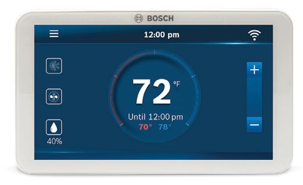
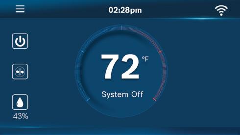
2 Bosch EasyAir Mobile App
This Heat Pump has connectivity features which enable remote and on-site monitoring of the system. Download the Bosch EasyAir app on your smartphone and create an account to get started.
1. Download the Bosch EasyAir app on your smartphone by searching for it in Google Play Store (for Android devices) or App Store (for iPhone). Alternatively, you can scan this QR code with your phone’s camera:

2. Launch the Bosch EasyAir App, create a profile and add the unit to the app to view on-site and remote system data when starting up the system in Section 15.
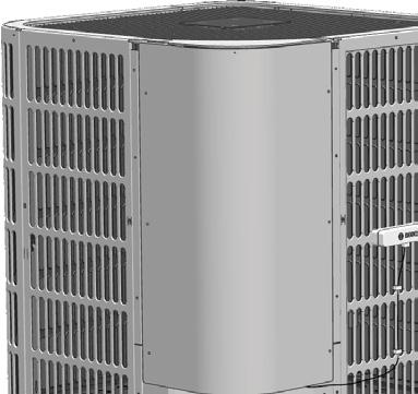
3 Unit Location Considerations
3.1 Unit Dimensions
BOVA60-20 33-3/16 x 29-1/8 x 29-1/8
Table 2
The unit’s weight values are on the carton box.
When mounting the outdoor unit on a roof, be sure the roof will support the unit’s weight. Properly selected isolation is recommended to prevent sound or vibration transmission to the building structure.
Installation and Operating Instructions Bosch IDS Premium Connected BOVA20 Series Condensing Unit - BTC 762003301 A (04.2024) | 11
Figure 1
Scan QR Code
Figure 2
Models H x W x L (Inches)
24-15/16
BOVA36-20
x 29-1/8 x 29-1/8
W H L
Figure 2
3.2 Refrigerant Piping Limits
2
3
Table 3
* Standard line size is recommended; N/A: Application not recommended; Refrigerant charge: refer to Sec. 14
• Maximum line equivalent length = 150 feet.
• Maximum vertical equivalent length = 50 feet.
• Use only the line diameters indicated in Table 3.
• If the suction linesets are greater than 50 feet, do not use a larger suction line than recommended.
Installation and Operating Instructions Bosch IDS Premium Connected BOVA20 Series Condensing Unit - BTC 762003301 A (04.2024) 12 |
System Capacity Model Liquid Line Suction Line Total Equivalent Length - Feet 25 50 75 100 125 150 Inch O.D. Maximum Vertical Separation - Feet
3/4 Std. 25 50 45 40 30 25 5/8 Opt. 25 50 45 40 30 25
Ton 3/8 *
Ton 3/8 * 3/4 Std. 25 50 50 50 35 25 5/8 Opt. 25 50 50 50 35 25
Ton 3/8 * 7/8 Std. 25 50 50 40 30 25 3/4 Opt. 25 50 50 40 30 25
Ton
* 7/8 Std. 25 50 50 40 30 25 3/4 Opt. 25 50 50 40 30 25 1 1/8 Opt. 25 40 N/A N/A N/A N/A
4
5
3/8
Standard Lineset Lineset 150' Max Line Length 50' Max Line Lift 50' Max Line Lift
Figure 3
3.3 Location Restrictions
WARNING
Flammable refrigerant!
Appliance shall be installed, operated in a room that meets special requirements and has an area limit as shown in Section 3.4
WARNING
Flammable refrigerant!
The outdoor unit shall be located in a well-ventilated location other than the occupied space, such as in the open air.
For installation of the indoor unit, refer to the corresponding installation and operation manual. If an indoor unit is installed in an unventilated area, the area shall be so constructed that should any refrigerant leak, it will not stagnate so as to create a fire or explosion hazard.
Ensure the top discharge area is unrestricted for at least 60 inches above the unit.
Do not locate outdoor unit near bedrooms since normal operational sounds may be objectionable.
Position unit to allow adequate space for unobstructed airflow, wiring, refrigerant lines, and serviceability.
Allow a minimum of 12 in. clearance on one side of control board access panel to a wall and a minimum of 24 in. on the adjacent side of control board access panel.
Maintain a distance of 24 in. between units.
Position unit where water, snow, or ice from roof or overhang cannot fall directly on unit.
Only use this unit in well-ventilated spaces and ensure that there are no obstructions that could impede the airflow into and out of the unit. Do not use this unit in the following locations:
• Locations with mineral oil.
• Locations with saline atmospheres, such as seaside locations.
• Locations with sulphurous atmospheres, such as near natural hot springs.
• Where high voltage electricity is present, such as in certain industrial locations.
• On vehicles or vessels, such as trucks or ferry boats.
• Where exposure to oily or very humid air may occur, such as kitchens.
• In proximity to sources of electromagnetic radiation, such as highfrequency transmitters or other high strength radiation devices.
See Fig. 4 and Fig. 5.
Installation and Operating Instructions Bosch IDS Premium Connected BOVA20 Series Condensing Unit - BTC 762003301 A (04.2024) | 13
Figure 4
Avoid Installations Near Bedrooms
Min. 60" Unrestricted
Min. 12" to Shrubbery
Access
Min. 24" Unrestricted
Panel
Figure 5
Min. 12" to Shrubbery
Access Panel
Min. 24" to Shrubbery
Cold climate considerations (heat pump only)
Precautions must be taken for units being installed in areas where snow accumulation and prolonged below-freezing temperatures occur.
• Units should be elevated 3-12 inches above the pad or rooftop, depending on local weather. This additional height will allow drainage of snow and ice melted during defrost cycle prior to its refreezing. Ensure that drain holes in unit base pan are not obstructed, which could prevent the drainage of defrost water (Fig. 6).
• If possible, avoid locations that are prone to snow drifts. If not possible, a snow drift barrier should be installed around the unit to prevent a buildup of snow on the sides of the unit.
Using a 5-point support system with snow legs is an effective way to distribute the weight of the outdoor unit, specifically supporting the compressor within it. This setup helps to prevent stress on individual points and ensures that the weight is evenly distributed, reducing the risk of damage or instability, especially in snowy conditions. By providing multiple points of contact, you're enhancing the unit's stability and longevity, which is crucial for its efficient operation over time.
3.4 Refrigerant Charge and Room Area Limitations
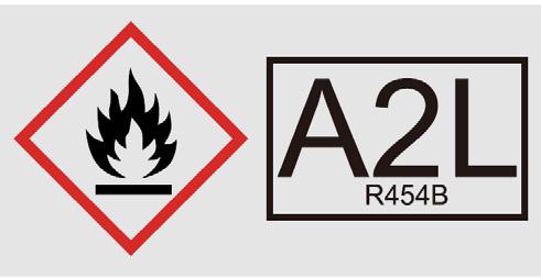
In UL/CSA 60335-2-40, R454B refrigerant is classified as class A2L, which is mildly flammable. Therefore, R454B refrigerant is suitable for systems needing additional refrigerant charge and which will limit the area of the rooms being served by the system.
Similarly, the total amount of refrigerant in the system shall be less than or equal to the allowable maximum refrigerant charge. The allowable maximum refrigerant charge depends on the area of the rooms being served by the system.
Check if the minimum room area meets the requirements
Determine the room size and the refrigerant system configuration
Calculate the total refrigerant charge (Mc) according to section 16.1
Check the corresponding table to get the maximum refrigerant charge (Mmax)
1. Decrease piping length by changing layout
2. Increase the smallest room area.
3. Add additional measures as described in applicable legislation.
The terms in this section are explained as follows:
Corrosive Environment
Exposure to a corrosive environment may shorten the life of the equipment, corrode metal parts, and/or negatively affect unit performance. Corrosive elements include, but are not limited to: sodium chloride, sodium hydroxide, sodium sulfate, and other compounds commonly found in ocean water, sulfur, chlorine, fluorine, fertilizers, and various chemical contaminants from industry/manufacturing plants. If installed in areas which may exposed to corrosive environments, special attention should be given to the equipment placement and maintenance.
• Lawn sprinklers/hoses/waste water should not spray directly on the unit cabinet for prolonged periods of time.
• In coastal areas: locate the unit on the side of the building away from the waterfront.
• Fencing or shrubbery may provide some shielding protection to the unit, however minimum unit clearances must still be maintained.
• Approximately every three months, wash the outdoor coil and any exposed cabinet surfaces.
• Mc: The actual refrigerant charge in the system.
• A: the actual room area where the appliance is installed.
• Amin: The required minimum room area.
• Mmax:The allowable maximum refrigerant charge in a room.
• Qmin: The minimum circulation airflow.
• Anvmin:The minimum opening area for connected rooms.
• TAmin: The total area of the conditioned space (For appliances serving one or more rooms with an air dut system).
• TA: The total area of the conditioned space connected by air ducts.
Installation and Operating Instructions Bosch IDS Premium Connected BOVA20 Series Condensing Unit - BTC 762003301 A (04.2024) 14 |
Figure 6
Min. 12" Snow barrier
Pad
3-12"
Elevation Snow legs
Figure 7
OK No Yes
Mc ≤ Mmax
3.4.1 The Room Area Calculation Requirements
CAUTION
Flammable refrigerant!
The space considered shall be any space which contains refrigerant-containing parts or into which refrigerant could be released.
The room area (A) of the smallest, enclosed,occupied space shall be used in the determination of the refrigerant quantity limits.
For determination of room area (A) when used to calculate the refrigerant charge limit, the following shall apply.
The room area (A) shall be defined as the room area enclosed by the projection to the base of the walls, partitions and doors of the space in which the appliance is installed.
Spaces connected by only drop ceilings, ductwork, or similar connections shall not be considered a single space.
Units mounted higher than 70-55/64 inches and spaces divided by partition walls that are no higher than 62-63/64 inches shall be considered a single space. Rooms on the same floor and connected by an open passageway between the spaces can be considered a single room when determining compliance to Amin, if the passageway complies with all of the following.
1. It is a permanent opening.
2. It extends to the floor.
3. It is intended for people to walk through.
The area of the connected rooms, on the same floor,connected by permanent opening in the walls and/or doors between occupied spaces, including gaps between the wall and the floor, can be considered a single room when determining compliance to Amin, provided all of the following conditions are met as shown in Figure 8.
Low level opening:
1. The opening shall not be less than Anvmin in Table 4.
2. The area of any openings above 11-13/16 inches from the floor shall not be considered in determining compliance with Anvmin.
3. At least 50% of the opening area of Anvmin shall be below 7-7/8 inches from the floor.
4. The bottom of the opening is not more than 3-15/16 inches from the floor.
5. The opening is a permanent opening that cannot be closed.
6. For openings extending to the floor the height shall not be less than 25/32 inches above the surface of the floor covering.
High level opening:
1. The opening shall not be less than 50% of Anvmin in Table 4.
2. The opening is a permanent opening that cannot be closed.
3. The opening shall be at least 59 inches above the floor.
4. The height of the opening is not less than 25/32 inches.
Room size requirement:
1. The room into which refrigerant can leak, plus the connected adjacent room(s) shall have a total area not less than Amin. Amin is shown in Table 6.
2. The room area in which the unit is installed shall be not less than 20% Amin. Amin is shown in Table 6.
The requirement for the second opening can be met by drop ceilings, ventilation ducts, or similar arrangements that provide an airflow path between the connected rooms.
The minimum opening for natural ventilation (Anvmin) in connected rooms is related to the room area (A), the actual refrigerant charge of refrigerant in the system (Mc) , and the allowable MAXIMUM REFRIGERANT CHARGE in the system (Mmax), Anvmin can be determined according to Table 4.
8
The minimum opening area for connected rooms:
Table 4
Note: Take the Mc=17 lbs 3 oz as an example.
Installation and Operating Instructions Bosch IDS Premium Connected BOVA20 Series Condensing Unit - BTC 762003301 A (04.2024) | 15
≥ 50% of Anvmin ≥25/32'' ≥25/32' ≥59'' ≤11-13/16' ≤3-15/16' ≤7-7/8'' Anvmin ≥ 50% of Anvmin
Figure
A (ft2) Mc (lbs/oz) Mmax (lbs/oz) Anvmin (ft2) lbs oz lbs oz 100 17 3 6 10 1.3 110 17 3 7 5 1.2 120 17 3 8 0 1.1 130 17 3 8 10 1.0 140 17 3 9 5 1.0 150 17 3 10 0 0.9 160 17 3 10 10 0.8 170 17 3 11 5 0.7 180 17 3 12 0 0.6 190 17 3 12 10 0.5 200 17 3 13 5 0.5 210 17 3 14 0 0.4 220 17 3 14 10 0.3 230 17 3 15 5 0.2 240 17 3 16 0 0.1 250 17 3 16 10 0.1 260 17 3 17 5 0.0
For appliances serving one or more rooms with an air duct system, The room area calculation shall be determined based on the total area of the conditioned space (TA) connected by ducts taking into consideration that the circulating airflow distributed to all the rooms by the appliance integral indoor fan will mix and dilute the leaking refrigerant before entering any room.
3.4.2 The Allowed Maximum Refrigerant Charge and Required Minimum Room Area
If the fan incorporated to an appliance is continuously operated or operation is initiated by a REFRIGERANT DETECTION SYSTEM with a sufficient CIRCULATION AIRFLOW rate, the allowable maximum refrigerant charge (Mmax) and the required minimum room area (Amin/TAmin) is shown in Table 5 and Table 6.
The allowable maximum refrigerant charges:
Table 5
Table 7
CAUTION
Min. room area and airflow required!
The allowable maximum refrigerant charge of the Table 5 or the required minimum room area of the Table 6 is available only if the following conditions are met:
Minimum velocity of 3.28ft/s, which is calculated as the indoor unit airflow divided by the nominal face area of the outlet. And the grill area shall not be deducted.
Minimum airflow rate must meet the corresponding values in Table 7, which is related to the actual refrigerant charge of the system (Mc).
R454B refrigerant leakage sensor is configured.
The maximum refrigerant limit described above applies to unventilated areas. If adding additional measures, such as areas with mechanical ventilation or natural ventilation, The maximum refrigerant charge can be increased or the minimum room area can be reduced.
R454B refrigerant leakage sensor is configured for the indoor unit, meets the incorporated circulation airflow requirements the maximum refrigerant charge or minimum room area can be determined according to Table 5 or Table 6.
CAUTION
Min. room area and airflow required!
If the actual room area, air outlet height, and refrigerant charge amount are not reflected in the above table, more severe cases need to be considered according to the data in the tables 4, 5 ,6 & 7.
Bosch IDS Premium Connected BOVA20 Series Condensing Unit - BTC 762003301 A (04.2024) 16 |
Installation and Operating Instructions
A/TA (ft2) Mmax (lbs/oz) A/TA (ft2) Mmax (lbs/oz) lbs oz lbs oz 40 2 10 160 10 10 50 3 5 170 11 5 60 4 0 180 12 0 70 4 10 190 12 10 80 5 5 200 13 5 90 6 0 210 14 0 100 6 10 220 14 10 110 7 5 230 15 5 120 8 0 240 16 0 130 8 10 250 16 10 140 9 5 260 17 5 150 10 0 - - -
The required minimum room area: Mc (lbs/oz) Amin/TAmin (ft2) Mc (lbs/oz) Amin/TAmin (ft2) lbs oz lbs oz 4 6 66.1 11 0 165.3 4 13 72.7 11 7 171.9 5 4 79.3 11 14 178.5 5 11 86.0 12 5 185.1 6 2 92.6 12 12 191.7 6 9 99.2 13 3 198.4 7 0 105.8 13 10 205.0 7 7 112.4 14 1 211.6 7 15 119.0 14 8 218.2 8 6 125.6 14 15 224.8 8 13 132.2 15 6 231.4 9 4 138.8 15 14 238.0 9 11 145.5 16 5 244.6 10 2 152.1 16 12 251.2 10 9 158.7 17 3 257.9
The minimum circulation airflow: Mc (lbs/oz) Qmin(CFM) Mc (lbs/oz) Qmin (CFM) lbs oz lbs oz 4 6 119 11 0 298 4 13 131 11 7 310 5 4 143 11 14 322 5 11 155 12 5 334 6 2 167 12 12 346 6 9 179 13 3 358 7 0 191 13 10 370 7 7 203 14 1 382 7 15 215 14 8 394 8 6 227 14 15 406 8 13 239 15 6 418 9 4 251 15 14 430 9 11 263 16 5 442 10 2 275 16 12 454 10 9 287 17 3 466
Table 6
4 Unit Preparation
4.1 Prepare the Unit for Installation
• Check for damage and report promptly to the carrier any damage found to the unit (Fig. 9).
• The charge port can be used to ensure the refrigerant charge has been retained during shipment.
NOTICE
Product damage!
Appliances shall be transported, marked and stored in accordance with the applicable warnings form section 1.3 in mind. The appliance shall be stored so as to prevent mechanical damage from occurring.
5 Setting the Unit
5.1 Pad Installation
When installing the unit on a support pad, such as a concrete slab, consider the following:
• The pad must be at least 1-2” larger than the unit on all sides.
• The pad must be separated from any structure.
• The pad must be level.
• The pad must be high enough above grade to allow for drainage.
• The pad location must comply with National, State, and local codes.
These instructions are intended to provide a method to tie-down system to cement slab as a securing procedure for high wind areas. Check local codes for tie-down methods and protocols.
NOTICE
Product damage!
The outdoor unit vapour service valve and liquid service valve need to be protected. do not grab them when moving the outdoor unit.
#7 X 3/8" Self-tapping screws (Do not exceed 3/8" length screws!)
A
Field-supplied brackets: 2" width, 1/16" thickness, height as required.
1/4” Χ 1-1/2” Hex washer head concrete screws (3/16” pilot hole needed. Pilot hole should be 1/4” deeper than the fastener embedment)
11
Installation and Operating Instructions Bosch IDS Premium Connected BOVA20 Series Condensing Unit - BTC 762003301 A (04.2024) | 17
Figure 9
Figure 10
Figure
Detail
See Section 2.1 for unit dimensions
See Detail A
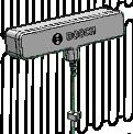
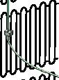
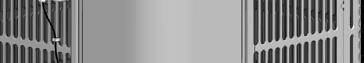
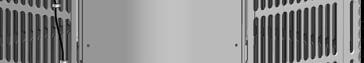
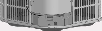
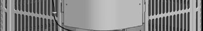
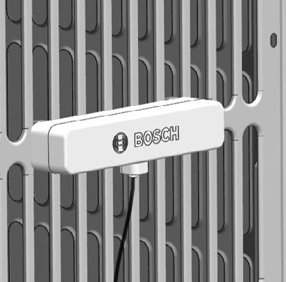
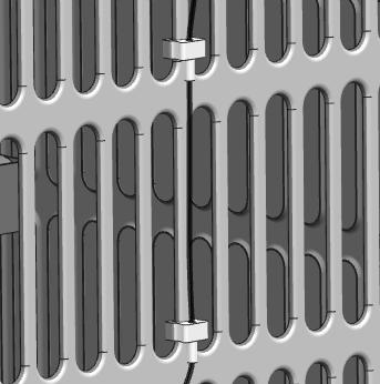
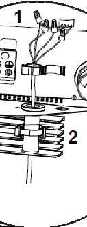
5.2 Mounting Antenna
The antenna is used to transmit data to the cloud and will have the strongest signal strength mounted furthest away from a wall or building.
1. Mount antenna on top of louver 3 (Refer to figure 12) on the left or right side of the unit depending on which is furthest from a wall. Slide the antenna downwards to mount the antenna and secure the cable using the 2 movable clips on the cable. Refer to figure 13.


Installation and Operating Instructions Bosch IDS Premium Connected BOVA20 Series Condensing Unit - BTC 762003301 A (04.2024) 18 |
3 3 2 2 1 1 IDS 2.2 ODU 5T Antenna Mounting IDS 2.2 ODU 3T Antenna Mounting
Figure 12
Mount antenna away from wall
Mount antenna away from wall
Figure 13
Clip antenna by sliding downwards on louver
Secure cable to outdoor unit with two clips
Building Wall
6 Refrigerant Line Considerations
6.1 Refrigerant Line and Service Valve Connection Sizes
6.4 Reuse Existing Refrigerant Lines
If using existing refrigerant lines, make certain that all joints are brazed, not soldered.
For retrofit applications, where the existing refrigerant lines will be used, the following precautions should be taken:
8
6.2 Required Refrigerant Line Length
Determine required line length (Fig. 14). Refer to Section 2.2.
The Suction Line must always be insulated. DO NOT allow the Liquid Line and Suction Line to come in direct (metal to metal) contact.
• Ensure that the refrigerant lines are the correct size. Refer to Section 3.2 and Table 3.
• Ensure that the refrigerant lines are free of leaks, acid, and oil.
The manufacturer recommends installing only approved matched indoor and outdoor systems. All of the manufacturer’s split systems are AHRI rated only with TXV indoor systems. The benefits of installing approved matched indoor and outdoor split systems are maximum efficiency, optimum performance and the best overall system reliability.
7 Refrigerant Line Routing
7.1
Precautions
Take precautions to prevent noise within the building structure due to vibration transmission from the refrigerant lines. For example:
• When the refrigerant lines have to be fastened to floor joists or other framing in a structure, use isolation type hangers.
• Isolation hangers should also be used when refrigerant lines are run in stud spaces or enclosed ceilings.
• Where the refrigerant lines run through a wall or sill, they should be insulated and isolated.
• Isolate the lines from all ductwork.
• Minimize the number of 90º turns.
NOTICE
Product damage!
The pipe-work including piping material, pipe routing, and installation shall include protection from physical damage in operation and service, and be in compliance with national and local codes and standards, such as ASHRAE 15, ASHRAE 15.2, IAPMO Uniform Mechanical Code, ICC International Mechanical Code. Inspection prior to being covered or enclosed,or CSA B52. All field joints shall be accessible for inspection prior to being covered or enclosed.
Installation and Operating Instructions Bosch IDS Premium Connected BOVA20 Series Condensing Unit - BTC 762003301 A (04.2024) | 19
Models Suction Line Liquid Line Suction Line Connection Liquid Line Connection Dimensions in inches BOVA36-20
3/8
BOVA60-20 7/8 3/8 7/8 3/8 Table
3/4
3/4 3/8
Figure 14 Line Length 6.3 Refrigerant Line Insulation
Figure
Liquid Line Suction Line Insulation
15
CAUTION MINOR TO MODERATE BURN!
Secure Suction Line from joists using isolators every 8 ft. Secure Liquid Line directly to Suction Line using tape, wire, or other appropriate method every 8 ft.
Isolation From Joist/Rafter
Secure Suction Line using isolators every 8 ft. Secure Liquid Line directly to Suction Line using tape, wire, or other appropriate method every 8 ft.
Isolation On Walls
to Suct ionL ineu si ng tape ,w ir e, or ot he rapp ropriate met hod ev er y8 ft.
Comply with National, State, and local codes when isolating linesets from joists, rafters, walls, or other structural elements.
Installation and Operating Instructions Bosch IDS Premium Connected BOVA20 Series Condensing Unit - BTC 762003301 A (04.2024) 20 |
Side View 8 Feet
Feet
Joist/Rafter Isolator
Figure 16
Maximum 8
Maximum
Lineset
Figure 17
8 ft
Side View 8 Feet
8 Feet
Wall Isolator Linesets
Secure Suct ionL ineu si ng isol at or seve ry
Secure Li qu id Li ne directly
Maximum
Maximum
8 Refrigerant Line Connection
All joints made in the installation between parts of the REFRIGERATING SYSTEM, with at least one part charged, shall be made in accordance with the following:
• A brazed, welded, or mechanical connection shall be made before opening the valves to permit refrigerant to flow between the REFRIGERATING SYSTEM parts. A vacuum valve shall be provided to evacuate the interconnecting pipe or any uncharged REFRIGERATING SYSTEM part.
• Mechanical connectors used indoors shall comply with ISO 14903. When mechanical connectors are reused indoors, sealing parts shall be renewed. When flared joints are reused indoors, the flare part shall be refabricated.
• Refrigerant tubing shall be protected or enclosed to avoid damage.
• Flexible refrigerant connectors (such as connecting lines between the indoor and outdoor unit) that may be displaced during NORMAL OPERATION shall be protected against mechanical damage.
Compliance is checked according to the installation instructions and a trial installation, if necessary.
Field-made refrigerant joints indoors shall be tightness tested. The test method shall have a sensitivity of 5 grams per year of refrigerant or better under a pressure of at least 0.25 times the maximum allowable pressure. No leak shall be detected.
For installations with field applied joints that are exposed in the occupied space,these joints shall be at least one of the following:
• Mechanical joints in compliance with ISO 14903 or UL 207 (U.S. only).
• Welded or brazed joints.
• Joints in enclosures that vent to the unit or to the outside.
Compliance is checked by inspection and tests.
Installation and Operating Instructions Bosch IDS Premium Connected BOVA20 Series Condensing Unit - BTC 762003301 A (04.2024) | 21
Figure 18
Lineset
Suction Line Sealant Insulation Wall Isolation Through Wall DO NOT hang linesets from ductwork
Isolator
Ductwork
9 Refrigerant Line Brazing
Alll R454B products have a red tag on the refrigerant lines to indicate the product is charged with A2L refrigerant. It should not be removed.
9.1 Braze The Refrigerant Lines
1. Remove caps or plugs. Use a deburring tool to deburr the pipe ends. Clean both internal and external surfaces of the tubing using an emery cloth.
This pipe must have a push pin that hits the valve core
21
4. Wrap a wet rag around the valve body to avoid heat damage and continue the dry nitrogen purge (Fig. 22).
Braze the refrigerant lines to the service valves.
Braze the filter drier to the Liquid Line.
All units come standard with a bi-flow filter drier. Braze the filter drier to the liquid line, using caution not to push the refrigerant line too hard past the stop within the filter drier (this could damage the drier).
The locking cap might be required by your local code enforcement.
2. Remove the pressure tap cap from both service valves.
Remove the wet rag before stopping the dry nitrogen purge.
Shipped in package field installed
3-4" from valve
20
3. Purge the refrigerant lines and indoor coil with dry nitrogen.
22
Installation and Operating Instructions Bosch IDS Premium Connected BOVA20 Series Condensing Unit - BTC 762003301 A (04.2024) 22 |
Figure 19
Figure
Figure
Figure
5. Replace the pressure tap caps after the service valves have cooled.
10 Refrigerant Line Leak Check
10.1 Check For Leaks
1. Pressurize the refrigerant lines and evaporator coil to 250 PSIG using dry nitrogen.
2. Check for leaks by using a soapy solution or bubbles at each brazed location.
Installation and Operating Instructions Bosch IDS Premium Connected BOVA20 Series Condensing Unit - BTC 762003301 A (04.2024) | 23
Figure 23
Figure 24
250 PSIG
Figure 25
11.1 Evacuate the Refrigerant Lines and Indoor Coil
Do not open the service valves until the refrigerant lines and indoor coil leak check and evacuation are complete.
1. Evacuate until the micron gauge reads no higher than 350 microns, then close the valve to the vacuum pump.
12 Service Valves
12.1 Open the Service Valves WARNING
Moderate to severe burns!
Extreme caution should be exercised when opening the Liquid Line Service Valve. Turn counterclockwise until the valve stem just touches the rolled edge. No torque is required. Failure to follow this warning will result in abrupt release of system charge and may result in personal injury and /or property damage.
2. Observe the micron gauge. Evacuation is complete if the micron gauge does not rise above 500 microns in one (1) minute.
Once evacuation is complete, turn off the vacuum pump and micron gauge, and close the valves on the manifold gauge set.
Leak check and evacuation must be completed before opening the service valves. The brazed lineset valves should be used for leak checking and vacuuming. Using the separate suction port for this process will result in loss of charge.
The Suction Service Valve must be opened first BEFORE opening the Liquid Service Valve.
1. Remove Service Valve Cap (Fig. 28).
2. Fully insert hex wrench into the stem and back out counterclockwise until valve stem just touches the rolled edge (approximately five (5) turns.)
3. Replace the Valve Stem Cap to prevent leaks. Tighten finger tight plus an additional 1/6 turn.
4. Repeat STEPS 1 - 3 for Liquid Service Valve.
5/16" Hex Wrench for Suction Service Valve
3/16" Hex Wrench for Liquid Service Valve

Rolled Edge to Captivate Stem
Hex Headed Valve System
Installation and Operating Instructions Bosch IDS Premium Connected BOVA20 Series Condensing Unit - BTC 762003301 A (04.2024) 24 |
11 Evacuation
0350 Microns ON OFF
Figure 26
1MIN.
Figure 27
Figure 28 Cap
Service Port Unit
Service Valve
Side of
13 Electrical - Low Voltage
13.1 Low Voltage Maximum Wire Length
Table 9 defines the maximum total length of low voltage wiring from the outdoor unit, to the indoor unit, and to the thermostat.
13.2 Low Voltage Hook-Up Diagrams
Voltage Unit Connections
13.3 Thermostat Wiring
• Be sure power supply agrees with equipment nameplate.
• Power wiring and grounding of equipment must comply with local codes.
• Low voltage wiring to be No. 18 AWG minimum conductor.
• “
-” Field installed electric auxiliary heat connection
• Single-stage auxiliary heating supported by 2H thermostat
• Twin-stage auxiliary heating supported by 3H thermostat
• W1: The first stage of field installed electric auxiliary heat.
• W2: The second stage of field installed electric auxiliary heat.
• The outdoor unit W signal is connected to the electric auxiliary heat or the first stage electric auxiliary heat.
Figures 30-36 refer to thermostat wiring diagrams for the BOVB20/ BOVD20 and BVA20 manufacturer matched indoor and outdoor systems.
NOTES:
- Low voltage connection must be made inside the outdoor unit control board access panel.
- There is no terminal block for low voltage connections, wires must be spliced using field supplied wire nuts
- Field supplied wire nuts should be 22-16 gauge.
- Refer to unit wiring diagram for more information.


Dashed lines in the following thermostat wiring diagrams refer to optional wiring (wiring for Passive Dehumidification Function and/OR Electric Heat). For thermostat wiring please refer to the Owner’s Manual of the thermostat.
B terminal to be connected with thermostat (O/B) wiring. Reversing valve energizes in heating.
Installation and Operating Instructions Bosch IDS Premium Connected BOVA20 Series Condensing Unit - BTC 762003301 A (04.2024) | 25
24 Volts - Wire size Max. Wire Length 18 AWG 150 Ft. 16 AWG 225 Ft. 14 AWG 300 Ft.
Table 9
Figure
Control Board Access Panel
29
Low
- - - - - - -
13.3.1 Non-Communicating Set Up Dip switch configurations for non-communicating mode
• The factory default mode is conventional 24VAC non-communicating mode.
• This device can be configured to communicating.
Low voltage wire connections with outdoor unit, non-communicating
1. Peel off the half-stripped wires of the pre-installed wires.
2. Connect the conventional 24VAC non-communicating thermostat control wires to the field supplied wires.
Multicore wires used for 24VAC non-communicating thermostat control wires
The wires unused should be insulated To outdoor unit
Wires connections diagram
Installation and Operating Instructions Bosch IDS Premium Connected BOVA20 Series Condensing Unit - BTC 762003301 A (04.2024) 26 |
indoor unit dipswitch SW7-1
in OFF position [ ] 0 SW7-1 ON 1234 outdoor unit dipswitch
in OFF position [ ] 0 SW5-4 ON 1234
Figure 30
is
SW5-4 is
Figure 31 TH ERMO ST AT
Terminal Connect the wires by wire nut
Non- communicating thermostat wiring diagrams
AIR HANDLER UNIT
Note: Any time the electric heat elements are active, the indoor fan will run in high stage.
Support 3H and 2C thermostat non-communicating setup
Control wiring for HP systems
Figure 33
AIR HANDLER UNIT
Note: Any time the electric heat elements are active, the indoor fan will run in high stage.
Support 4H and 2C thermostat non-communicating setup
Control wiring for HP systems
Installation and Operating Instructions Bosch IDS Premium Connected BOVA20 Series Condensing Unit - BTC 762003301 A (04.2024) | 27
Figure 32 PURPLE YELLOW RED GREEN BLACK BLUE GRAY WHITE BROWN
W/E Y2 Y Y R G C O/B H/DH W1 W2 W Y2 Y1 R G C C B B DH P Q Y W C B P Q THERMOSTAT OUTDOOR UNIT BLACK BLUE YELLOW WHITE BLACK BLUE YELLOW WHITE
RED
GRAY WHITE BROWN
PURPLE YELLOW
GREEN BLACK BLUE
W/E W2 Y2 Y Y R G C O/B H/DH W1 W2 W Y2 Y1 R G C C B B DH P Q Y W C B P Q THERMOSTAT OUTDOOR UNIT BLACK BLUE YELLOW WHITE BLACK BLUE YELLOW WHITE
Note: Any time the electric heat elements are active, the indoor fan will run in high stage
Support 3H and 1C thermostat non-communicating setup
Control wiring for HP systems
Note: Any time the electric heat elements are active, the indoor fan will run in high stage
Support 2H and 2C thermostat non-communicating setup
Control wiring for HP systems
Installation and Operating Instructions Bosch IDS Premium Connected BOVA20 Series Condensing Unit - BTC 762003301 A (04.2024) 28 |
Figure 34
YELLOW RED
BLACK
GRAY WHITE BROWN
PURPLE
GREEN
BLUE
W/E W2 Y Y R G C O/B H/DH W1 W2 W Y2 Y1 R G C C B B DH P Q Y W C B P Q THERMOSTAT OUTDOOR UNIT
BLACK BLUE
YELLOW WHITE BLACK BLUE YELLOW WHITE
AIR HANDLER UNIT
Figure 35
YELLOW RED GREEN BLACK BLUE GRAY WHITE BROWN
PURPLE
Y Y Y R G C O/B H/DH W1 W2 W Y2 Y1 R G C C B B DH P Q Y W C B P Q THERMOSTAT OUTDOOR UNIT
BLACK BLUE YELLOW WHITE BLACK BLUE YELLOW WHITE
AIR HANDLER UNIT
PURPLE YELLOW RED GREEN BLACK BLUE GRAY WHITE BROWN
Note: Any time the electric heat elements are active, the indoor fan will run in high stage.
Support 1H and 1C thermostat non-communicating setup
Control wiring for HP systems
PURPLE
Note: Any time the electric heat elements are active, the indoor fan will run in high stage
Support 3H and 1C thermostat non-communicating setup
Control wiring for HP systems
Installation and Operating Instructions Bosch IDS Premium Connected BOVA20 Series Condensing Unit - BTC 762003301 A (04.2024) | 29
Figure 36
Y Y R G C O/B H/DH W1 W2 W Y2 Y1 R G C C B B DH P Q Y W C B P Q THERMOSTAT OUTDOOR UNIT BLACK BLUE YELLOW WHITE BLACK BLUE YELLOW WHITE AIR HANDLER UNIT
Figure 37
YELLOW RED GREEN BLACK BLUE GRAY WHITE BROWN
W/E Y Y R G C O/B H/DH W1 W2 W Y2 Y1 R G C C B B DH P Q Y W C B P Q THERMOSTAT OUTDOOR UNIT BLACK BLUE YELLOW WHITE BLACK BLUE YELLOW WHITE AIR HANDLER UNIT
13.3.2 Communicating Set Up Dip switch configurations for communicating mode
To setup the units as communication mode enable the indoor unit to transmit data effectively with a paired Bosch outdoor unit.
• This is not the factory default configuration, and both dipswitches must be in this state exactly to enable communication.
• Communication is only available with a BOSCH air handler and ODU system.
• PQ communication supports non-polar communication.
• If there are 2 or more systems (communication) in the same area, make sure the low voltage wires are connected to the right unit that are connected to the same refrigerant line.
• The above pictures are for indication, the actual object may be different.
Low voltage wire connections with the outdoor unit, communicating
1. Loosen the rubber ring of the communication cables hole, and remove the conventional 24VAC non-communicating thermostat control wires through the communication hole.
Installation and Operating Instructions Bosch IDS Premium Connected BOVA20 Series Condensing Unit - BTC 762003301 A (04.2024) 30 |
indoor unit dipswitch SW7-1 is in ON position [ ] 1 SW7-1 ON 1 234 outdoor unit dipswitch SW5-4 is in ON position [ ] 1 SW5-4 ON 1234
Figure 38
Figure 39
CN14 Control
Top panel
board
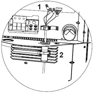
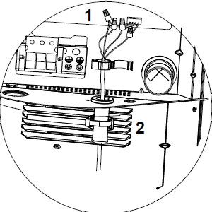
2. Take out the PQ communication wires from the accessory bag and plug it into CN30 on the control board.
3. Thread the two field supplied low voltage wires through the hole, and tighten the rubber ring of the low voltage wires hole.
Installation and Operating Instructions Bosch IDS Premium Connected BOVA20 Series Condensing Unit - BTC 762003301 A (04.2024) | 31
Figure 40
CN30 CN30
(In the accessory package)
Figure 41
Top panel
CN30
4. Connect the PQ communication wires to the two field supplied wires and connect the conventional 24VAC thermostat control wires with the thermostat.
42
Ensure the dip switches are configured correctly for communicating mode (see Fig. 31).
Communicating thermostat wiring diagrams
Note: Any time the electric heat elements are active, the indoor fan will run in high stage.
Support 3H and 2C thermostat communication mode setup
Control wiring for HP systems
Installation and Operating Instructions Bosch IDS Premium Connected BOVA20 Series Condensing Unit - BTC 762003301 A (04.2024) 32 |
used for PQ communication TH ERMO ST AT Terminal The wires unused should be insulated To outdoor unit Connect the wires by wire nut
Figure
Two-core wires or Multicore wires
PURPLE YELLOW RED GREEN BLACK BLUE GRAY WHITE BROWN
Figure 43
W/E Y2 Y Y R G C O/B H/DH W1 W2 W Y2 Y1 R G C C B B DH P Q Y W C B P Q THERMOSTAT OUTDOOR UNIT AIR HANDLER UNIT RED BLACK RED BLACK
PURPLE
YELLOW RED GREEN BLACK BLUE GRAY WHITE BROWN
Note: Any time the electric heat elements are active, the indoor fan will run in high stage.
Support 4H and 2C thermostat communication mode setup
Control wiring for HP systems
PURPLE YELLOW RED GREEN BLACK BLUE GRAY WHITE BROWN
Note: Any time the electric heat elements are active, the indoor fan will run in high stage
Support 3H and 1C thermostat communication mode setup
Control wiring for HP systems
Installation and Operating Instructions Bosch IDS Premium Connected BOVA20 Series Condensing Unit - BTC 762003301 A (04.2024) | 33
Figure 44
W/E W2 Y2 Y Y R G C O/B H/DH W1 W2 W Y2 Y1 R G C C B B DH P Q Y W C B P Q THERMOSTAT OUTDOOR UNIT AIR HANDLER UNIT RED BLACK RED BLACK
Figure 45
W/E W2 Y Y R G C O/B H/DH W1 W2 W Y2 Y1 R G C C B B DH P Q Y W C B P Q THERMOSTAT OUTDOOR UNIT AIR HANDLER UNIT RED BLACK RED BLACK
Note: Any time the electric heat elements are active, the indoor fan will run in high stage PURPLE
Support 2H and 2C thermostat communication mode setup
Control wiring for HP systems
Note: Any time the electric heat elements are active, the indoor fan will run in high stage
Support 1H and 1C thermostat communication mode setup
Control wiring for HP systems
Installation and Operating Instructions Bosch IDS Premium Connected BOVA20 Series Condensing Unit - BTC 762003301 A (04.2024) 34 |
Figure 46
YELLOW RED GREEN BLACK BLUE GRAY WHITE BROWN
Y Y Y R G C O/B H/DH W1 W2 W Y2 Y1 R G C C B B DH P Q Y W C B P Q THERMOSTAT OUTDOOR UNIT AIR HANDLER UNIT RED BLACK RED BLACK
Figure 47
YELLOW
PURPLE
RED GREEN BLACK BLUE GRAY WHITE BROWN
Y Y R G C O/B H/DH W1 W2 W Y2 Y1 R G C C B B DH P Q Y W C B P Q THERMOSTAT OUTDOOR UNIT AIR HANDLER UNIT RED BLACK RED BLACK
Note: Any time the electric heat elements are active, the indoor fan will run in high stage PURPLE YELLOW RED GREEN BLACK BLUE GRAY WHITE BROWN
Support 3H and 1C thermostat communication mode setup
Control wiring for HP systems
PQ communication mode and conventional 24VAC non-communicating thermostat control mode can not be used at the same time.
NOTICE
Product damage!
Do not interconnect different communication wires or conventional 24VAC non-communicating thermostat control wires (PQ, CBYW, etc.), otherwise it will damage the control board. The following example shows incorrect wiring.
Incorrect wiring example
Installation and Operating Instructions Bosch IDS Premium Connected BOVA20 Series Condensing Unit - BTC 762003301 A (04.2024) | 35
Figure 48
W/E Y Y R G C O/B H/DH W1 W2 W Y2 Y1 R G C C B B DH P Q Y W C B P Q THERMOSTAT OUTDOOR UNIT AIR HANDLER UNIT RED BLACK RED BLACK
PURPLE
RED
WHITE BROWN W/E Y2 Y Y R G C O/B H/DH W1 W2 W Y2 Y1 R G C C B B DH P Q Y W C B P Q THERMOSTAT OUTDOOR UNIT BLACK
WHITE
AIR
Figure 49
RED BLACK RED BLACK
YELLOW
GREEN BLACK BLUE GRAY
BLUE YELLOW
BLACK BLUE YELLOW WHITE
HANDLER UNIT
Installation and Operating Instructions Bosch IDS Premium Connected BOVA20 Series Condensing Unit - BTC 762003301 A (04.2024) 36 |
H/P
Model(Btu/h) 24 36 48 60 Power Phase Single Voltage/frequency 208/230VAC, 60Hz Line Gauge Input Current Fuse Indoor unit (A) 15A 15A 15A 15A Indoor Unit Power Line Line Quantity 3 3 3 3 Line Diameter (AWG) 14 14 14 14 Outdoor Unit Power Line Line Quantity 3 3 3 3 Line Diameter (AWG) 14 12 10 10 Outdoor -Indoor Signal Line Line Quantity 4 4 4 4 Line Diameter (AWG) 18 18 18 18 Thermostat Signal Line Line Quantity 5 5 5 5 Line Diameter (AWG) 18 18 18 18 Table 10
Electric wiring gauge for
systems
14 Electrical - High Voltage
14.1 High Voltage Power Supply WARNING
Live electrical components!
During installation, testing, servicing, and trouble shooting of this product, it may be necessary to work with live electrical components. Failure to follow all electrical safety precautions when exposed to live electrical components could result in death or serious injury.
The high voltage power supply must match the equipment nameplate (208/230V, 1PH, 60Hz).
Power wiring must comply with national, state, and local codes.
Follow instructions on unit wiring diagram located on the inside of the control box access panel and refer to wiring diagram in this IOM.
14.2 High Voltage Disconnect Switch
Install a separate disconnect switch at the outdoor unit.
Field supplied flexible electrical conduit must be used for high voltage wiring.
14.3 High Voltage Ground
Ground the outdoor unit per national, state, and local code requirements.
Installation and Operating Instructions Bosch IDS Premium Connected BOVA20 Series Condensing Unit - BTC 762003301 A (04.2024) | 37
Figure 50
Figure 51
1. Ensure Sections 7, 8, 9, 10, 11, and 12 have been completed.
2. Set System Thermostat to OFF.
Turn on disconnect to apply power to the indoor and outdoor units.
Once power is supplied to the outdoor unit. LEDS on the Gateway will turn on.
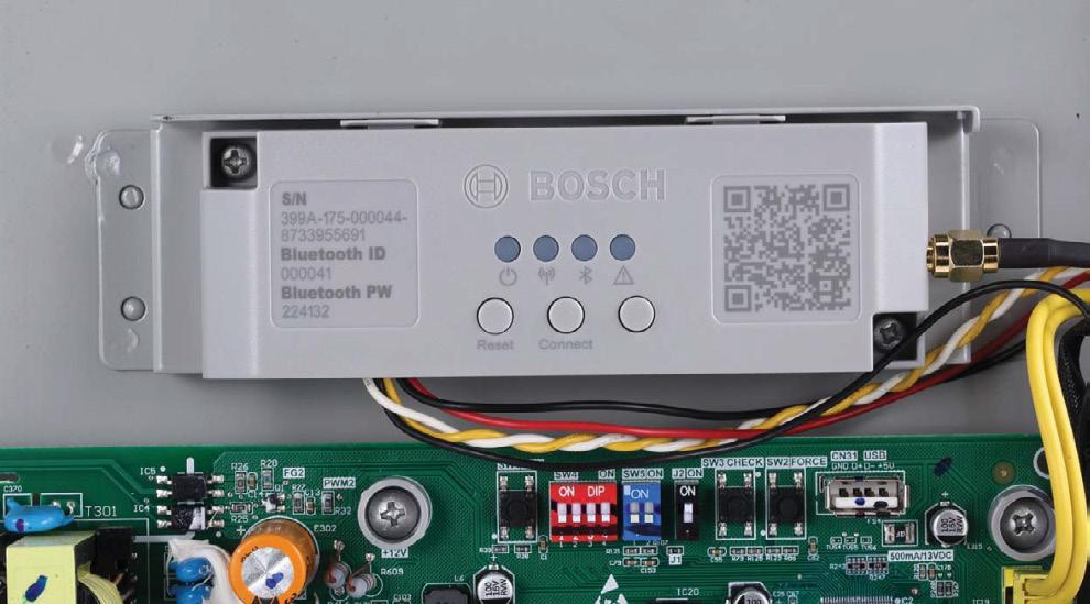


A LED sequence may flash on gateway for up to 6 minutes if there is a firmware update.
5. Open up the Bosch EasyAir app and "Add a New Unit". The app will prompt you to scan the outdoor unit Serial Number and Gateway QR code.
6. Once the outdoor unit is added, access the 'Remote Request' tab within the 'Unit Dashboard' to associate the unit to a homeowner.
Refer to the "EasyAir App Contractor User Manual" to learn more about the features of the app.
Installation and Operating Instructions Bosch IDS Premium Connected BOVA20 Series Condensing Unit - BTC 762003301 A (04.2024) 38 | 15 Start Up 15.1
System Start Up
Figure 52
3.
ON OFF
Figure 53
4.
Figure 54
Figure 55
Figure 56

7. Upon initial unit installation, wait one (1) hour before starting the unit if compressor crankcase heater is used and the outdoor ambient temperature is below 70 ºF.

Installation and Operating Instructions Bosch IDS Premium Connected BOVA20 Series Condensing Unit - BTC 762003301 A (04.2024) | 39
Figure 57
Figure 58 60 MIN.
8. Set system thermostat to ON.
Figure 59
16 System Charge Adjustment
Download and install the Bosch EasyAir app to assist in charging the unit.

16.1 Charging: Weigh-In Method
Use weigh-in method the initial installation, or anytime a system charge is being replaced. Weigh-in method can also be used when power is not available to the equipment site or operating conditions (indoor/outdoor temperatures) are not in range to verify with the subcooling charging method.
3
Table 11
The factory charge in the outdoor unit is sufficient for 15 feet of standard size interconnecting liquid line. New Installations — Calculating additional charge for lineset greater than 15 ft.
The only mode approved for validating system charge is while in Cooling "Force Mode". Outdoor temperature must be between 55°F and 120°F with indoor temperature kept between 70°F and 80°F.
16.2 Subcooling Charging And Refrigerant Adjustment In Cooling (Above 55°F Outdoor Temp.)
1. Check the outdoor ambient temperatures.
Subcooling (in cooling mode) is the only recommended method of charging above 55ºF outdoor ambient temperatures.
For outdoor ambient temperatures below 55ºF use weigh-in charge method.
It is important to return in the spring or summer to accurately charge the system in the cooling mode when outdoor ambient temperature is above 55ºF.
For best results, the indoor temperature should be kept between 70ºF and 80ºF during the install.
(c*d)
lineset is less than 15 ft, (e) = 0
Sealed-System Repairs — Calculating total system charge.
1. Total Line Length (ft) = _________(a)
2. Standard Lineset (ft) = 15 (b)
3. (a) minus (b) = _________(c)
4. Refrigerant Multiplier = 0.59 oz/ft (d) 5. Refrigerant Adder (c*d) = _________(e)*
6. Factory Charge (namplate) = _________(f)
7. Total System Charge (e+f) = ________ _
* If lineset is less than 15 ft, (e) = 0
Figure 62
2. Ensure Sections 7,8,9,10,11,12 and 13 have been completed.
Installation and Operating Instructions Bosch IDS Premium Connected BOVA20 Series Condensing Unit - BTC 762003301 A (04.2024) 40 |
Figure 60
Model Factory Charge Charge multiplier for interconnecting refrigerant tube length
Ton 6lbs 11oz 0.59 oz/ft 5 Ton 10lbs 3oz 0.59 oz/ft
1. Total Line Length (ft) = _________(a) 2. Standard Lineset (ft) = 15 (b) 3. (a) minus (b) = _________(c) 4. Refrigerant Multiplier = 0.59 oz/ft (d) 5. Refrigerant
Adder
= _________(e)* *If
55ºF Outdoor Temp1 120ºF Outdoor Temperature Above 55ºF 55ºF Outdoor Temp2 Outdoor Temperature Below 55ºF
Figure 61
80 ºF 70ºF Indoor
Temp
3. Stabilize the system.
After starting the system in cooling mode, short press “FORCE” button, and “ ” symbol should appear. System may take 10 minutes to ramp up. Operate the system for a minimum of twenty (20) minutes.
After a twenty (20) minute stabilization period operating at 100% capacity (i.e. once the compressor reaches the frequency shown in Table 11), maintain continuous operation while adjusting refrigerant charge. After adjusting, operate system for a minimum of five (5) minutes for system to stabilize, otherwise repeat step 3.
If calculated subcooling value is lower than the design subcooling value (Table 9), please add refrigerant. Repeat steps 3 through 5.
Table 12

63
4. Calculate superheat value (According to Table 12)
• Measured Suction Line Temp = ________ºF
• Measured Suction Line Pressure = _______ PSIG
• Calculate superheat value = ________ºF
Check the superheat and select correct subcooling according to superheat, refer to Table 12. It is recommended to keep the superheat at 10-18°F if a third party indoor unit is used.
5. Calculate subcooling value (According to Table 13)
• Measured Liquid Line Temp. = ________ºF
• Measured Liquid Line Pressure = _______ PSIG
• Calculate subcooling value = ________ºF
Table 13 R-454B Refrigerant chart - Final Superheat
Table 14 R-454B Refrigerant chart - Final Subcooling
Installation and Operating Instructions Bosch IDS Premium Connected BOVA20 Series Condensing Unit - BTC 762003301 A (04.2024) | 41
Compressor Frequency in Force Mode in Cooling ODU Capacity 2TON 3TON 4TON 5TON Frequency (HZ) 52 75 58 65
20 MIN.
Figure
Insulation
Figure 64
Suction Temp (°F) Final Superheat (°F) 6 8 10 12 14 16 18 20 22 Suction Gauge Pressure (PSIG) 40 95 91 87 84 80 77 74 70 67 42 99 95 91 87 84 80 77 74 70 44 103 99 95 91 87 84 80 77 74 46 107 103 99 95 91 87 84 80 77 48 111 107 103 99 95 91 87 84 80 50 116 111 107 103 99 95 91 87 84 52 120 116 111 107 103 99 95 91 87 54 125 120 116 111 107 103 99 95 91 56 129 125 120 116 111 107 103 99 95 58 134 129 125 120 116 111 107 103 99 60 139 134 129 125 120 116 111 107 103 62 144 139 134 129 125 120 116 111 107 64 149 144 139 134 129 125 120 116 111 66 155 149 144 139 134 129 125 120 116 68 160 155 149 144 139 134 129 125 120 70 166 160 155 149 144 139 134 129 125 72 171 166 160 155 149 144 139 134 129
If the superheat is out of range, refer to Troubleshooting section of this IOM.
Liquid Temp (°F) Final Subcooling (°F) 6 7 8 9 10 11 12 13 Liquid Gauge Pressure (PSIG) 55 164 167 170 172 175 178 181 184 60 178 181 184 187 191 194 197 200 65 194 197 200 203 206 210 213 217 70 210 213 217 220 223 227 230 234 75 227 230 234 238 241 245 249 252 80 245 249 252 256 260 264 268 272 85 264 268 272 276 280 284 288 292 90 284 288 292 297 301 305 309 314 95 305 309 314 318 323 327 332 336 100 327 332 336 341 346 351 355 360 105 351 355 360 365 370 375 380 385 110 375 380 385 390 396 401 406 412 115 401 406 412 417 422 428 433 439 120 428 433 439 445 450 456 462 468 125 456 462 468 474 480 486 492 498
Table 15
* Optimized range for superheat/subcool
6. Adjust refrigerant level to attain proper gauge pressure.
Add refrigerant if the subcooling reading from Table 13 is lower than the designed value (Table 14).
• Connect gauges to refrigerant bottle and unit as illustrated (Fig. 52).
• Purge all hoses.
• Open tank.
• Stop adding refrigerant when subcooling matches the design value (Table 14).
• Remove gauges.
• Replace ser vice port caps to prevent leaks. Tighten finger tight plus an additional 1/6 turn.
8. Record System Information for reference (Table 15).
Record system pressures and temperatures after charging is complete.
Table 16
16.3 Record the Refrigerant Charge Amount
After refrigerant is charged, record the amount of refrigerant to be charged on the label of the outdoor unit. 1 indicates the amount of refrigerant to be charged by the factory, 2 indicates the additional refrigerant, and 1 + 2 indicates the total refrigerant to be charged.
Recover refrigerant if the subcooling reading from Table 13 is higher than the design value (Table 14).
65
7. Stabilize the system.
• Wait 5 minutes for the system condition to stabilize between adjustments.
When the subcooling matches the design value (Table 14), the system is properly charged.
66
Installation and Operating Instructions Bosch IDS Premium Connected BOVA20 Series Condensing Unit - BTC 762003301 A (04.2024) 42 | Design Subcooling Model Subcooling/°F Superheat/°F 24K/36K 8-12* 10-18* 6-10 7-10 48K 6-10* 9-18* 4-8 7-9 60K 6-10* 8-18* 4-8 6-8
Figure
Description Value Outdoor model number Measured Outdoor Ambient °F Measured Indoor Ambient °F Measured Liquid Line Temp °F Measured Suction Line Temp °F Liquid Gauge Pressure PSIG Suction Gauge Pressure PSIG
kg kg kg
Figure
17 System Operation and Troubleshooting
Download and install the Bosch EasyAir app to assist in troubleshooting the unit.
17.1 Control Logic Description
• The variable speed system adopts the same 24VAC control as any conventional heat pump.
• The compressor’s speed is controlled based on coil pressures monitored by the unit's pressure transducer. To ensure stable and adequate capacity, the compressor speed will modulate relative to evaporator pressure during cooling operation and relative to condensing pressure during heating operation. The target pressure can automatically adjust based on compressor operation so optimal capacity can be achieved. Target pressure can be manually adjusted (SW4) to achieve improved dehumidification and capacity demands.

• Accelerated cooling/heating function changes the initial target coil temperature to provide "enhanced comfort" by increasing unit capacity.
17.2 Sensors (Thermistors/Pressure Transducer)
• T3 = Outdoor Coil Temperature (Table 20)
◦ High/Low temperature protection
◦ Outdoor fan control (cooling mode)
◦ Defrost control (heating mode)
• T4 = Ambient Temperature (Table 20)
◦ Operating condition permission
◦ Defrosting condition permission
◦ Outdoor fan control (heating mode)
• T5 = Compressor Discharge Temperature (Table 21)
◦ High/Low temperature protection
◦ Electronic Expansion Valve (EEV) (ODU/heating mode only)
• Th = Compressor Return Temperature (Table 20)
• T3L = Liquid Line Temperature (Table 20)
• TF = IPM Radiator Temperature (Table 21)
◦ Inverter High Temperature Protection
• Pc = Condensing Pressure Transducer
◦ Compressor frequency control
◦ High pressure protection (cooling mode)
◦ Low pressure protection (heating mode)
• Pe = Evaporating Pressure Transducer
◦ Compressor frequency control
◦ Electronic Expansion Valve (EEV) control (heating mode only)
◦ High pressure protection (heating mode)
◦ Low pressure protection (cooling mode)
17.3 Pressure Equalizer Valve (PEV)
Used to balance the pressure in the system before compressor start up.
17.4 Defrost Description
• The Demand Defrost Control (DDC) monitors the ODU coil temperature using thermistor (T3). A second thermistor (T4) monitors outdoor ambient temperature. Based on these parameters, as well as accumulative run time and high pressure, the DDC calculates proper initiation of defrost.
• Any one of the below three conditions is required to enter defrost:
1. The calculated temperature difference between the outdoor temperature (T4) and the coil temperature (T3) is called Delta T. After Delta T is achieved and continues for 3 minutes.
◦ T4 ≥ 39°F, Delta T = 18°F
◦ T4 ≥ 30°F, Delta T = 16°F
◦ T4 ≥ 19°F, Delta T = 14°F
◦ When T4 < 19°F, T3 < 9°F, accumulative compressor run time ≥ 80 minutes.
Table 17
*Factory Default
• Adaptive capacity function is a "self-learning function" which allows a range of target coil temperatures to adapt for better unit operation and reduced short cycling.
2. After “Minimum Run Time” (MRT) is achieved. MRT is based on outdoor ambient temperature (T4), for example:
◦ MRT is 4 hours when: T4 < 23°F
◦ MRT is 2 hours when: 23°F ≤ T4 < 42°F
3. After the high pressure saturation temperature drops below 82°F for 20 minutes.
Installation and Operating Instructions Bosch IDS Premium Connected BOVA20 Series Condensing Unit - BTC 762003301 A (04.2024) | 43
Figure 67
68 ON OFF 1 2 3 4 SW4 Switch Description SW4-1 ON Unused OFF* Must be set at "OFF" position SW4-2 ON Unused OFF* Must be set at "OFF" position SW4-3 ON Adaptive capacity output disabled OFF* Adaptive capacity output enabled SW4-4 ON Accelerated cooling/heating OFF* Normal cooling/heating
Figure
• Defrost will terminate once outdoor coil temperature (T3) reaches 64°F for a period of 1 minute or defrost time has exceeded 8 minutes.
• Defrost Termination Settings (SW5) offers different defrost termination options for enhanced defrost for different geographical and outdoor conditions.
SW5-1 ON Heating time reduced 10% OFF Normal *
SW5-2 ON Defrosting extended for 60 seconds OFF Normal *
SW5-3 ON Quiet Mode OFF Normal*
SW5-4 ON Communication mode OFF Non-communicating mode*
Table 18
• Manual Defrost:
1. System must have a call for heat and have been operating for a minimum of 8 minutes.
2. Press “Force” button on inverter board for 6 seconds to begin forced defrost.
3. Wait approximately 40 seconds for defrost to initiate.
4. Once defrost initiates, the display will indicate “dF”.
5. Defrost test will terminate automatically, after which the display will indicate running speed.
6. If a second defrost test is required, repeat steps 2-5 after 5 minutes.
17.5 Compressor Crankcase Heater Description
Refrigerant migration during the OFF cycle can result in noisy start-ups, therefore a CrankCase Heater (CCH) is used to minimize refrigerant migration thereby minimizing start-up noise and/or bearing “wash out”. All CCHs must be installed on the lower half of the compressor shell. Its purpose is to warm the compressor during the OFF cycle, driving refrigerant from compressor. After extended shutdown periods in cold weather, it is recommended to allow CCH to be energized for at least 12 hours prior to compressor operation by applying line voltage to heat pump with thermostat OFF.
• CCH operation energizes:
1. First time line voltage is applied and compressor discharge temperature T5 < 53.6°F.
2. Compressor stops running for 3 hours (outdoor ambient temperature T4 < 41°F OR compressor discharge temperature T5 < 53.6°F).
• CCH operation de-energizes:
1. Compressor discharge temperature T5 ≥ 60.8°F.
2. Compressor start running.
17.6 Reversing Valve Operation
• Reversing valve energizes during heat mode and de-energizes in cool mode.
During a heat call on first time operation the unit will run about 1 minute in cooling to build up pressure for reversing valve to change.
17.7 Protection Functions
• Outdoor coil temperature protection (T3)
i. If T3 > 143.6°F, compressor is de-energized.
ii. If T3 < 129.2°F, compressor is energized.
• Ambient temperature protection (T4)
i. If 15°F ≤ T4 < 125°F, unit can operate in cooling.
ii. If ‒4°F ≤ T4 < 86°F, unit can operate in heating.
iii. If T4 < ‒13°F, heat pump will provide 24V control to indoor unit energizing electric heat (if installed).
See BOVB20 & BOVD20 Product Specification for extended performance data.
• Discharge Temperature (DT) protection (T5)
i. If DT > 239°F during cooling mode, the compressor will stop.
ii. If DT < 194°F during cooling mode, the compressor will restart.
iii. If DT > 221°F during heating mode, the compressor will stop.
iv. If DT < 167°F during heating mode, the compressor will restart.
• High Pressure (HP) protection (mechanical open/close pressure switch)
i. High Pressure Switch opens at P > 580 PSIG, the compressor and outdoor fan stop.
ii. High Pressure Switch closes at P < 435 PSIG, the compressor and outdoor fan restart.
• Low Pressure (LP) protection
i. If Low Pressure < 43.5 PSI for 5 minutes during cooling mode, the compressor and outdoor fan will stop.The system will attempt to run again after 6 minutes.
ii. If condensing temp. Tc < outdoor ambient temp. T4 during heating mode, the compressor and outdoor fan will stop.
• Module (inverter) protection (TF)
i. If TF > 203°F, the compressor and outdoor fan will stop.
ii. If TF < 176°F, the compressor and outdoor fan will restart.
• Low discharge superheat protection
i. Head discharge superheat HDSH<9°F last 40minutes.
Operating
Bosch IDS Premium Connected BOVA20 Series Condensing Unit - BTC 762003301 A (04.2024) 44 |
Installation and
Instructions
ON OFF 1 2 3 4 SW5 DIP Switch Description
Figure 69
Table 19
Code
Fault Description (Sensor)
AtL Ambient Temperature Limited(T4)
b2 Temperature sensor fault in indoor unit (T2)
b3 R454B refrigerant sensor fault in indoor unit
b4 R454B refrigerant sensor communication fault in indoor unit
b5 Communication fault between indoor unit and outdoor unit
b7 R454B refrigerant leakage protection in indoor unit
b8 R454B refrigerant sensor over service life in indoor unit
C3 The coil sensor is seated fault in cooling (T3)
E41 Temperature sensor fault (T3)
E42 Temperature sensor fault (T3L)
E43 Temperature sensor fault (T4)
E44 Temperature sensor fault (T5)
E45 Temperature sensor fault (Th)
E51 Outdoor unit high/low input voltage protection
E52 Outdoor unit high/low DC bus voltage protection
E7 Compressor discharge sensor is seated fault (T5)
E81 EEVA coil fault
EA Control program does not match drive program in outdoor unit
F1 High pressure switch protection (HPS)
F2 5 times (P2) protection in 100 minutes, system lockout
F41 High pressure sensor fault
F42 Low pressure sensor fault
H01 Drive chip Communication fault in outdoor unit
J00-JCF Compressor drive fault
n00-nCF Fan drive fault
P0 Compressor IPM temperature protection(TF)
P1 High pressure switch protection (HPS)
P11 High pressure protection in cooling/heating (Pc)
P21 Low pressure protection in cooling/heating (Pe)
P31 Outdoor unit input over current protection
P32 Compressor over current protection
P4 High compressor discharge temperature protection (T5)
P5 Condensor coil temperature protection in cooling (T3)
PH Low discharge superheat protection
* Fault requires hard restart
Installation and Operating Instructions Bosch IDS Premium Connected BOVA20 Series Condensing Unit - BTC 762003301 A (04.2024) | 45 17.8 Fault
Code Table
17.9 System Protection Status Codes
Code Description
Forced operation mode
Running indication under high pressure
Running indication under low pressure
Running indication under return oil mode
Running indication under current limited condition
Running indication under T5 limited condition
Running indication under COMP. IPM Temp. limited condition
Running indication under compressor ratio limited condition
Running indication under low voltage limited condition
Running indication under defrost mode
Table 20
* If the first digit shown on the control board LED is one of the following protection codes (followed by two numerical digits which show the current compressor frequency in Hz), the unit will continue to run but in a limited condition. The only exception is when the system is in defrost mode, which only displays "dF" (without any numerical digits following).
Installation and Operating Instructions Bosch IDS Premium Connected BOVA20 Series Condensing Unit - BTC 762003301 A (04.2024) 46 |
17.10 Parameter Point Check Table
• To display system parameters, press the “Check” button to index through the series of parameters available. The first time you press the “Check” button, it will display the sequence, and after 1 second it will display the value of the parameter. If you press the “Check” button again, it will display the next sequence. Refer to Figure 57 and 58 for check button location on the control board.
• Normal Status, last two digits will display under the following conditions i. Unit not operating (Standby Mode); “outdoor ambient temperature”. ii. Unit operating; displays “compressor operating frequency”.
• After 20 seconds on same parameter, the display will revert back to normal status.
• If a system protection is active, first digit will display “status code”.
Installation and Operating Instructions Bosch IDS Premium Connected BOVA20 Series Condensing Unit - BTC 762003301 A (04.2024) | 47
No. Point check content Example Remark 0 Outdoor unit capacity: H5=Heat pump 5 ton H5 H5=Heat Pump 5 ton 1 Outdoor unit mode: 0-standby, 2-cooling, 3-heating 2 0 standby, 2 cooling, 3 heating 2 Outdoor unit set compressor speed 56 Hz 3 System last fault code E4 system 4 Liquid valve subcooling (°F) 10 °F 5 Gas valve superheat (°F) 10 °F 6 T3: outdoor coil temp.(°F) 108 °F 7 T3L: outdoor coil outlet temp.(°F) 102 °F 8 T4: outdoor ambient temp.(°F) 95 °F 9 T5: compressor discharge temp.(°F) 140 °F 10 Th: compressor suction temp.(°F) 55 °F 11 Compressor IPM temp.(°F) 120 °F 12 Pe: evaporating pressure(psig) 130 psig 13 Pc: condensing pressure(psig) 320 psig 14 Tes: target evaporating temp.(°F) (only for cooling mode) 43 °F 15 Te: evaporating temp.(°F) 43 °F 16 Tcs: target condensing temp.(°F)(only for heating mode) 106 °F 17 Tc: condensing temp.(°F) 106 °F 18 Target value of the compressor discharge superheat(°F) (only for heating mode) 36 °F 19 Compressor discharge superheat (°F) 36 °F 20 Compressor Suction superheat (°F) 10 °F 21 Openings of EEVA(P) 200 0-480P 22 Fan speed stage 8 (0-10) 23 Outdoor unit fan current(A) 1 A 24 Compressor current(A) 10 A 25 Outdoor unit input current(A) 10 A 26 Outdoor unit input voltage(V) 230 V 27 Outdoor unit DC bus voltage(V) 380 V 28 Outdoor unit power(*0.1kW) 200 Outdoor unit * 0.1 kW 29 Continuous running time of the compressor(min) 35 minutes/0-999/Maintain at maximum 30 Outdoor unit main control software version 11 11 31 Indoor unit Heat Kit Staging 1 0~3 32 T2: indoor unit coil temp.(°F) (only for communication mode) 55 °F 33 Indoor unit software version(only for communication mode) 11 34 reserved - - -35 Remark“--” - - -Table 21
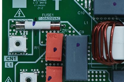
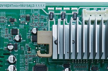
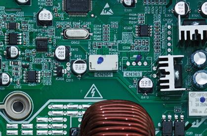
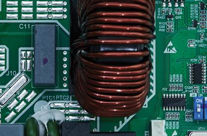
Function Description
Power output (Reserve)
Compressor crankcase heater port
Pressure equalizer valve port
Reversing valve port
Thermostat wire connections
Indoor unit comm. bus port
USB port
Gateway connector
J2 Dip SWITCH: select capacity
SW4 Dip SWITCH: Control logic settings
SW5 Dip SWITCH: Defrost logic settings
EEVA port
High pressure transducer port
Low pressure transducer port
Debug
T4 sensor port
T3 sensor port
T3L sensor port
T5 sensor port
Th sensor port
High pressure switch port
SW1 FORCE BUTTON
SW2 CHECK BUTTON
Display
Debugging port
ECM motor port
Compressor: W port
Compressor: V port
Compressor: U port
Po w er input
Po w er input
Installation and Operating Instructions Bosch IDS Premium Connected BOVA20 Series Condensing Unit - BTC 762003301 A (04.2024) 48 | 17.11 Control Board Overviews Main
Model
Control Board for 24/36 ODU
70 1 2 3 4 5 6 8 12 7 13 14 15 16 17 18 19 20 9 10 11 21 22 23 24 26 27 28 29 25 30 31 No. 1 2 3 4 5 6 7 8 9 10 11 12 13 14 15 16 17 18 19 20 21 22 23 24 25 26 27 28 29 30 31
Figure
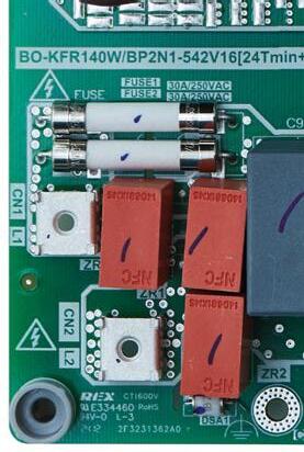
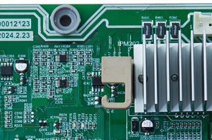
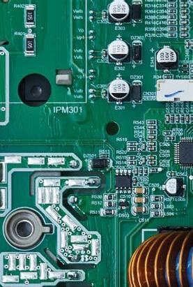
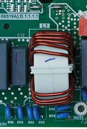
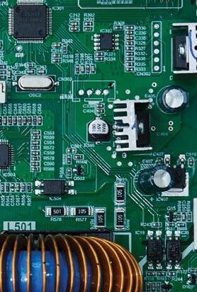
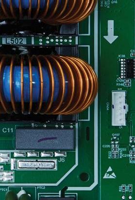
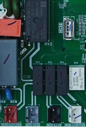

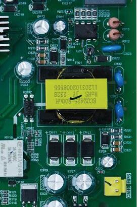
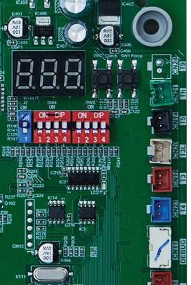
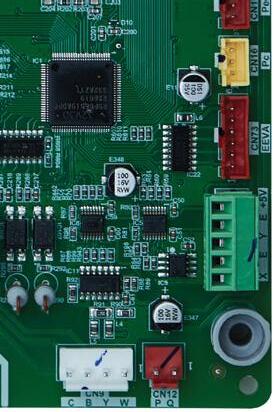
Function Description
Power output(Reserve)
Compressor crankcase heater port
Pressure equalizer valve port
Reversing valve port
Thermostat wire connections
Indoor unit comm.port
USB port
Gateway wire connections
J2 Dip SWITCH:Select capacity
SW4 Dip SWITCH:Defrost logic settings
SW5 Dip SWITCH:Control logic settings
EEVA port
High pressure transducer port
Low pressure transducer port
Debugging port
T4 sensor port
T3 sensor port
T3L sensor port
T5 sensor port
Th sensor port
SW1 FORCE BUTTON
SW2 CHECK BUTTON
Digital tube
High pressure switch port
Debugging port
ECM motor port
Compressor: W port
Compressor: V port
Compressor: U port
Power input
Power input
Installation and Operating Instructions Bosch IDS Premium Connected BOVA20 Series Condensing Unit - BTC 762003301 A (04.2024) | 49
Main Control Board for 48/60 ODU Model
No. 1 2 3 4 5 6 7 8 9 10 11 12 13 14 15 16 17 18 19 20 21 22 23 24 25 26 27 28 29 30 31
Figure 71
1 2 3 4 5 6 8 12 7 13 14 15 16 17 18 19 20 9 10 11 21 22 23 24 26 27 28 29 25 30 31
17.12 Error Code Troubleshooting
WARNING
Hazardous voltage!
When measuring resistance , make sure the unit is powered off and wait 3 min before taking measurement.
WARNING
Hazardous voltage!
When measuring resistance , make sure the unit is powered off and wait 3 min before
72
Is the ambient te mperat ur e beyond operating range?
Cooling mode: 15-125°F
Heating mode: -4-86°F
Is the thermo st at set to energize O/B in heating mode?
Is the T4 sensor seated correctly?
Is the T2 sensor seated normally?
se rv ic e re quir ed. Wait for temperature to be within range
Is the sensor resistance 0 or very high?
Corr ec t th ermo stat setting
Restart the unit. Is the problem solved?
Refe r to wi ring di agra m fo r correct wiring
Figure 73
Replace indoor control board.
Reinstall the sensor.
Yes Replace the sensor.
Troubleshooting complete.
Is the resist ance of T4 in the range of Table 20?
Replac e T4 sensor
Restart sy stem
74
Installation and Operating Instructions Bosch IDS Premium Connected BOVA20 Series Condensing Unit - BTC 762003301 A (04.2024) 50 |
Figure
No
Yes No Yes No No Yes No Yes Fault code AtL Description (Sensor) Ambient Temperature Limited Condition
taking measurement.
No
No
Yes
No
No Fault code b2 Description
Indoor unit
sensor fault
(Sensor)
T2
Indoor
Figure
unit T2 sensor fault
Is the A2L sensor seated normally? No
Replace the A2L refrigerant sensor and power the unit back up.
No Reinstall the sensor.
Is there a refrigerant leak in line set?
Recover refrigerant, replace line set or reweld leakage point.
Is P or Q Wire incorrectly connected? No
Are ODU Dipswitch SW5-4 and IDU Dipswitch SW7-1 correct?
Is P or Q wire shorted or touching sheet metal?
Yes Correct wiring at CN12 on ODU and CN30 on IDU.
Correct Dip Switch Settings
Are there other flammable gases in the area?
Open a window or ventilate the space.
Replace IDU Control Board and restart unit. Has Fault cleared?
Replace ODU Control Board and restart unit. No
Arrange P and Q wire so it is not touching other wires or any sheet metal.
78
Replace R454B refrigerant sensor and restart system.
Replace the A2L refrigerant sensor and power the unit back up
Normal operation.
Installation and Operating Instructions Bosch IDS Premium Connected BOVA20 Series Condensing Unit - BTC 762003301 A (04.2024) | 51
Figure 75
Fault code b4 Description (Sensor) Indoor unit A2L refrigerant sensor communication fault
code b5 Description
Figure 76
Fault
(Sensor) Communication Fault between IDU and ODU Yes No
Yes
No
Fault code b7 Description (Sensor) R454B refrigerant Leakage fault in indoor unit No Yes
Figure 77
Yes
No
Fault code b8 Description
Indoor unit
refrigerant sensor
ser vice life
Figure
(Sensor)
A2L
past
WARNING
Hazardous voltage!
When measuring resistance , make sure the unit is powered off and wait 3 min before taking measurement.
Fault code C3
Description (Sensor) T3 sensor is not reading correctly in cooling
Is sensor T4 exposed to heat?
Is the location of sensor T3 incorrect?
Yes
Remove source of heat.
Yes Correct the location.
Is sensor T3 wired incorrectly?
Refer to wiring diagram for correct wiring configurations
Is the resistance of sensor T3 not in range of Table 15?
Replace T3 Sensor. Yes No
Is sensor T4 wired incorrectly?
Refer to wiring diagram for correct wiring configurations Yes
Is the resistance of sensor T4 no t in range of table 15?
No
Replace the control board.
Replace the T4 sensor. Yes
WARNING
Hazardous voltage!
When measuring resistance , make sure the unit is powered off and wait 3 min before taking measurement.
Fault code E41
Description (Sensor) T3 temperature sensor fault
Are the wire connections to the control board incorrect? (CN19) No
Is the sensor T3 in open or short circuit?
Replace the control board. No
Did the sensor T3 fail?
Yes Correct the connection.
Yes Replace the failed sensor.
Replace the failed sensor.
Installation and Operating Instructions Bosch IDS Premium Connected BOVA20 Series Condensing Unit - BTC 762003301 A (04.2024) 52 |
Figure 79
No
No Yes
No
No
Figure 80
No Yes
WARNING
Hazardous voltage!
When measuring resistance , make sure the unit is powered off and wait 3 min before taking measurement.
Fault code E42 Description (Sensor) T3L temperature sensor fault
Are the wire connections to the control board incorrect? (CN20)
No
Is the sensor T3L in open or short circuit?
Yes Correct the connection
Yes Replace the failed sensor.
WARNING
Hazardous voltage!
When measuring resistance , make sure the unit is powered off and wait 3 min before taking measurement.
Fault code E43 Description (Sensor) T4 temperature sensor fault
Are wire connections to the control board incorrect? (CN23)
No
Is the sensor T4 in open or short circuit?
Yes Correct the connection
Did the sensor T3L fail?
Replace the failed sensor. No Yes
Replace the control board.
81
Did the sensor T4 fail?
Yes Replace the failed sensor.
82
Replace the control board.
Replace the failed sensor.
Installation and Operating Instructions Bosch IDS Premium Connected BOVA20 Series Condensing Unit - BTC 762003301 A (04.2024) | 53
Figure
No
Figure
No
No
Yes
WARNING
Hazardous voltage!
When measuring resistance , make sure the unit is powered off and wait 3 min before taking measurement.
Fault code E44 Description (Sensor) T5 temperature sensor fault
Are the wire connections to the control board incorrect? (CN14)
No
Is the sensor T5 in open or short circuit?
Replace the control board. No
Did the sensor T5 fail?
Yes Correct the connection
Yes Replace the failed sensor.
WARNING
Hazardous voltage!
When measuring resistance , make sure the unit is powered off and wait 3 min before taking measurement.
Fault code E45 Description (Sensor) Th temperature sensor fault
Are the wire connections to the control board incorrect? (CN21) No
Is the sensor Th in open or short circuit?
Yes Correct the connection
83
Replace the failed sensor. No Yes
84
Replace the control board. No
Did the sensor Th fail?
Yes Replace the failed sensor.
Replace the failed sensor.
Installation
Operating Instructions Bosch IDS Premium Connected BOVA20 Series Condensing Unit - BTC 762003301 A (04.2024) 54 |
and
Figure
Figure
No Yes
Is the hi gh voltage po we r su pply ≥270V?
Is the hi gh voltage po we r su pply ≤172V?
Is the voltage between P-N (CN3) <310V?
Restart sy stem
power supply/call utility provider
Is the input power wiring incorrect?
Correctly wire the input power
Is input power lower than 172VAC or higher than 270 VAC?
Is there a fault in standby mode?
Replac e cont rol board
Is the resistance between any two fan motor connectors U2/V2/W2 less than 50 ohm? Is the resistance from any connector to ground higher than 1M ohm?
Ensure input power is between 187VAC and 253VAC
Replace the outdoor unit control board
Replace the outdoor unit fan motor
Is the resistance between any two compressor connectors U/V/W less than 1 ohm? Is the resistance from any connector to ground higher than 1M ohm?
Replace the outdoor unit control board
Replace the compressor
Installation and Operating Instructions Bosch IDS Premium Connected BOVA20 Series Condensing Unit - BTC 762003301 A (04.2024) | 55
Fault code E51 Description (Sensor) Outdoor unit high/low input voltage protection
Figure 85
Correct power supply/call utility provider
Yes No Yes No Yes No
Correct
Fault code E52 Description (Sensor) Outdoor unit high/low DC bus voltage protection
Figure 86
Yes No
Yes
No
Yes
No
No Yes
No Yes
Hazardous voltage!
When measuring resistance , make sure the unit is powered off and wait 3 min before taking measurement.
87 Fault code E7 Description (Sensor) T5 sensor not reading correctly
Is the lo ca tion of the T5 sensor wrong?
the T5 and Tf sensors wired correctly?
Is the resist ance of T5 in the range of Table 21?
Installation and Operating Instructions Bosch IDS Premium Connected BOVA20 Series Condensing Unit - BTC 762003301 A (04.2024) 56 |
WARNING
Figure
Corr ec t th e location Restart
Refe r to wi ring di agra m fo r correct wiring Yes No No Yes Yes No
Replace
sy stem
Are
T5 Sensor
Description
Yes Normal operation.
No Correct
wiring
wiring
Is
Yes No
Figure
88 Fault code E81
(Sensor) EEVA coil fault Replace the outdoor unit control board.
Replace EEV coil and restart. Is the fault cleared?
the
according to the
diagram.
EEV coil wiring seated normally?
Fault
EA
Control program does not match drive program in outdoor unit Yes Normal
fault
No
Figure 89
code
Description (Sensor)
operation. Upgrade the correct main control chip program. Is the
cleared?
Replace the control board in the outdoor unit and restart.
Is there poor connection at CN10 or wrong connection on control board? No
Did the high pressure switch fail?
Is the system overcharged? Is there noncondensable gas?
Replace the control board and restart the system.
Correct the issues by referencing the wiring diagram.
the high pressure switch Adjust the refrigerant charge to the correct amount.
the wire connection secure at CN16? Is there obvious damage?
the connection or replace the transducer
Installation and Operating Instructions Bosch IDS Premium Connected BOVA20 Series Condensing Unit - BTC 762003301 A (04.2024) | 57
Fault code
Description
High
Figure 90
F1
(Sensor)
pressure switch protection (HPS)
No Yes Replace
No Yes
Yes
Fault code F41 Description (Sensor) High pressure sensor fault Yes Replace
pressure
Replace
Yes Did
Did
Yes Correct
No No
Figure 91
the
transducer
the control board.
the pressure transducer fail?
the control board fail?
Is
Fault code F42 Description (Sensor) Low pressure sensor fault Yes Replace
Replace
Yes Did
Did the
fail? Yes Correct
Is
No No
Figure 92
the pressure transducer
the control board.
the pressure transducer fail?
control board
the connection or replace the transducer.
the wire connection secure at CN15? Is there obvious damage?
WARNING
Hazardous voltage!
When measuring resistance , make sure the unit is powered off and wait 3 min before taking measurement.
Fault code P0 Description (Sensor) Control Board is over-heated
WARNING
Hazardous voltage!
When measuring resistance , make sure the unit is powered off and wait 3 min before taking measurement.
Fault code P1 Description (Sensor) High pressure protection
Yes
Replace the control board in the ODU and restart the system
Are the compressor module IPM1 screws loose?
No
Is the radiator air duct of the electric control box dirty or blocked?
Yes Tighten the IPM1 screws.
Are service valves closed or are refrigerant lines bent or blocked?
No
In cooling mode with ambient temp above 125 F (120 F for force mode) or in heating mode with ambient temp above 86 F?
Yes
Open the valves or correct the blockage.
Clean air duct of electric control box radiator to prevent blockage. No Yes
Are components on back of ODU control board evenly coated with thermal paste?
Is there a fault in standby mode? No No
Replace the control board and restart the system
Yes Apply thermal paste correctly and reinstall control board. Restart the system
Did the high pressure switch fail?
No need for service. Out of range operation. Yes Yes
Replace the high pressure switch
Is the system overcharged?
Adjust the refrigerant charge to the correct amount.
Is there poor heat exchange on the high pressure side?
Replace the fan motor.
Installation and Operating Instructions Bosch IDS Premium Connected BOVA20 Series Condensing Unit - BTC 762003301 A (04.2024) 58 |
Figure 93
Figure 94
Yes
No No
Yes
No
95
Are service valves closed or are refrigerant lines bent or blocked?
No
In cooling mode with ambient temp above 125 F (120 F for force mode) or in heating mode with ambient temp above 86 F?
Yes
Open the valves or correct the blockage.
e
Is there abno rmal pressure in the system?
No need for service. Out of range operation.
Is there poor heat exchange on the high pressure side?
Did the sensor Pc fail?
Replace the fan motor.
Clear any blockage in the refrig erant,C orrect poor he at ex ch ange (air flow restriction, motor failure)
Is the sy st em unde rc ha rg ed? Adju st re fr igeran t
Run unit in cooling or heating mode. Is the suction pressure within 50 PSI of checkpoint No.9 (cooling) or No.10 (heating)?
Restart system
Replace the failed sensor.
Is the system undercharged?
Adjust the refrigerant charge to the correct amount.
Replac e pres su re transducer
Installation and Operating Instructions Bosch IDS Premium Connected BOVA20 Series Condensing Unit - BTC 762003301 A (04.2024) | 59
Figure
Fault code P11 Description (Sensor) High pressure protection in cooling/heating (Pc)
Yes Yes Yes Yes No No No
Fault
Description
Figure 96
code P21
(Sensor) Low pressure protection
Are th
se rv ic e va lves open? Op en the se rv ice va lves
Yes No Yes No Yes No No Yes
F2 System lockout, P2 occurs 5 times
100 minutes
in
WARNING
Hazardous voltage!
When measuring resistance , make sure the unit is powered off and wait 3 min before taking measurement.
Is there a fault in standby mode?
Are service valves closed or wires to the compressor not fastened?
Yes Replace the control board in the ODU and restart the system
Does the ODU input current match ODU point check value no.25?
Is the resistance between compressor ports U/V/W > 1 ohm or each to ground <1M ohm?
Yes Open the valves or correct the wiring according to the wiring nameplate.
Is there a fault in standby mode? No
Are the service valves closed or the connecting wire to the compressor
Are there blockages in the ODU/IDU coils? Are there abnormal fan operations? Yes
Replace the control board in the ODU and restart the system
Open the valves or correct the wiring according to the wiring nameplate.
Remove the barriers causing the blockage or replace the fan.
Is the resistance between compressor ports U/V/W > 1 ohm or each to ground <1M ohm?
Normal op eration.
Yes Replace the compressor and restart the system
Restart the system after replacing the ODU control board, has the fault cleared?
98
Replace the compressor and restart the system. Yes
Replace the compressor and restart the system.
Restart system after replacing the ODU control board, has the fault cleared?
Replace the compressor and restart the system
Installation and Operating Instructions Bosch IDS Premium Connected BOVA20 Series Condensing Unit - BTC 762003301 A (04.2024) 60 |
Figure 97
Fault code P31 Description (Sensor) Outdoor unit input over current protection
No
No Yes
No No
No
Figure
Description
Fault code P32
(Sensor) Compressor over current protection
Yes Yes
Yes
No
No
No
Are the service valves closed or are the refrigerant lines bent or blocked? Yes
Open the valves or correct the blockage. No
In cooling mode with ambient temp above 125 F (120 F for force mode) or in heating mode with ambient temp above 86 F?
Is there poor heat exchange on the high pressure side?
No need for service. Out of range operation.
Are the service valves closed or are the refrigerant lines bent or blocked? Yes
Open the valves or correct the blockage.
Did the sensor T5 fail?
Replace the fan motor.
In cooling mode with ambient temp above 125 F (120 F for force mode) or in heating mode with ambient temp above 86 F?
Were sensors T4 and T5 switched after service?
Did the sensor T3 fail?
Replace the failed sensor.
Is the system undercharged?
Adjust the refrigerant charge to the correct amount.
Is there poor heat exchange on the high pressure side?
No need for service. Out of range operation.
Correct the sensor positions.
Replace the failed sensor.
Replace the fan motor.
Installation and Operating Instructions Bosch IDS Premium Connected BOVA20 Series Condensing Unit - BTC 762003301 A (04.2024) | 61
Fault code P4 Description (Sensor) High compressor discharge temperature protection (T5)
Figure 99
Yes Yes Yes Yes No No No
Fault code P5 Description (Sensor) Condenser coil temperature (T3) protection in cooling
Figure 100
No
Yes Yes Yes Yes No No No
Are yo u ru nning in forc e mode?
Is the ambient temperature >120°F?
Quit force mode
Are the service valves open?
Is there abno rmal pressure in the system?
Op en the se rv ice va lves
Clear any blockage in the refrig erant,Corr ec t poor he at ex ch ange (air flow restriction, motor failure)
Is the sy st em u nderc ha rg ed?
Adju st re fr igeran t No Yes
Is the resist ance of T5 in range of Table 21?
Is the resist ance of T3 in range of Table 20?
Replac e T5 sensor
R eplac e T3 sensor No Yes
Restart Syst em
Installation and Operating Instructions Bosch IDS Premium Connected BOVA20 Series Condensing Unit - BTC 762003301 A (04.2024) 62 |
Figure 101
Yes No
Yes No Yes
No Yes No
Yes No
Fault code PH Description (Sensor) Low discharge superheat protection
Temperature and Resistance Relationship Tables (for Sensors)
Table 22 for T3, T4, Th, T3L
Installation and Operating Instructions Bosch IDS Premium Connected BOVA20 Series Condensing Unit - BTC 762003301 A (04.2024) | 63
TEMP F TEMP C RESISTANCE kΩ VOLTS DC TEMP F TEMP C RESISTANCE kΩ VOLTS DC -5 -20.6 107.732 4.65 90 32.2 7.225 2.36 0 -17.8 93.535 4.60 95 35.0 6.401 2.21 5 -15.0 79.521 4.54 100 37.8 5.683 2.07 10 -12.2 67.795 4.47 105 40.6 5.057 1.93 15 -9.4 57.948 4.39 110 43.3 4.509 1.79 20 -6.7 49.652 4.30 115 46.1 4.028 1.67 25 -3.9 42.645 4.21 120 48.9 3.606 1.55 30 -1.1 36.710 4.10 125 51.7 3.233 1.43 40 4.4 27.386 3.86 130 54.4 2.902 1.32 45 7.2 23.732 3.73 135 57.2 2.610 1.22 50 10.0 20.610 3.59 140 60.0 2.350 1.13 55 12.8 17.939 3.45 145 62.8 2.119 1.04 60 15.6 15.648 3.30 150 65.6 1.914 0.96 65 18.3 13.681 3.15 155 68.3 1.731 0.88 70 21.1 11.987 2.99 160 71.1 1.574 0.82 75 23.9 10.527 2.83 165 73.9 1.416 0.75 80 26.7 9.265 2.67 170 76.7 1.276 0.68 85 29.4 8.172 2.52
17.13
23 for T5 & Tf
Installation
Operating Instructions Bosch IDS Premium Connected BOVA20 Series Condensing Unit - BTC 762003301 A (04.2024) 64 | 17.14
Tf
TEMP F TEMP C RESISTANCE kΩ VOLTS DC TEMP F TEMP C RESISTANCE kΩ VOLTS DC -5 -20.6 600.134 4.93 140 60.0 13.643 3.14 0 -17.8 505.551 4.92 145 62.8 12.359 3.03 5 -15.0 427.463 4.91 150 65.6 11.214 2.91 10 -12.2 362.739 4.89 155 68.3 10.227 2.80 15 -9.4 308.891 4.87 160 71.1 9.308 2.68 20 -6.7 265.398 4.85 165 73.9 8.485 2.56 25 -3.9 227.481 4.83 170 76.7 7.746 2.45 30 -1.1 195.601 4.80 175 79.4 7.105 2.34 35 1.7 168.707 4.77 180 82.2 6.504 2.23 40 4.4 146.695 4.74 185 85.0 5.963 2.13 45 7.2 127.258 4.70 190 87.8 5.474 2.02 50 10.0 110.707 4.66 195 90.6 5.032 1.92 55 12.8 96.572 4.61 200 93.3 4.645 1.83 60 15.6 84.465 4.56 205 96.1 4.28 1.73 65 18.3 74.411 4.51 210 98.9 3.949 1.64 70 21.1 65.408 4.45 215 101.7 3.648 1.56 75 23.9 57.634 4.39 220 104.4 3.383 1.48 80 26.7 50.904 4.32 225 107.2 3.133 1.40 85 29.4 45.258 4.24 230 110 2.904 1.32 90 32.2 40.152 4.16 235 112.8 2.694 1.25 95 35.0 35.699 4.08 240 115.6 2.503 1.18 100 37.8 31.807 3.99 245 118.3 2.334 1.12 105 40.6 28.398 3.89 250 121.1 2.172 1.06 110 43.3 25.506 3.80 255 123.9 2.024 1.00 115 46.1 22.861 3.70 260 126.7 1.888 0.95 120 48.9 20.529 3.59 265 129.4 1.767 0.90 125 51.7 18.47 3.48 270 132.2 1.651 0.85 130 54.4 16.708 3.37 275 135.0 1.544 0.80 135 57.2 15.085 3.26 280 137.8 1.446 0.76
and
Temperature and Resistance Relationship Tables (for T5 &
Sensors)
Table
18 Wiring Diagram
Installation and Operating Instructions Bosch IDS Premium Connected BOVA20 Series Condensing Unit - BTC 762003301 A (04.2024) | 65
Figure 102 SW4 1 2 3 4 ON SW2 Check CN10 CN73 HPS T3L EEVA CN20 DSP1 U Control Boar d GRAY/W BROWN/V BLACK/U CN396 CN1 L1 CN2 L2 YELLO W WHIT E B LUE CB Y W BLAC K RE D BLAC K The factory default * ON 1234 SW4 ON OFF SW1 Force For 36/60K mode For 24/48K mode Set capacity L1 L2 WARNIN G FAILURE TO FOLLOW THIS WARNING COULD RESULT IN PERSONAL INJURY OR DEATH ELECTRIC HAZARD 380 VOLTS DC WAIT 5 MINUTES AFTER DISCONNECTING POWER, THEN VERIFY DC VOLTAGE LESS THAN 42 VDC AT INVERTER TEST POINTS P-N. COMPONENTS MAY STORE A DANGEROUS ELECTRICAL POTENTIAL OF 380 VOLTS DC. J2 CN5 To indoor unit communication bus CN30 T3 CN19 T4 CN23 Pe CN15 Pc CN16 J2 1 ON SW5 1 2 3 4 ON CN9 Gateway Antenna Reset Connect Factory PEV CN6 CN18 CN31 LED3 USB * ON 1234 SW5 ON OFF CN12 J2 1 ON ON OFF 1 ON ON OFF 1 ON ON OFF LED1 COMP U V W Y/G BROWN BLACK GRAY SW4-2 SW4-3 SW4-4 SW4-1 * * * SW5-2 SW5-3 SW5-4 SW5-1 * * HPSHigh pressure switch T5 Comp. discharge temp. sensor T3 Outdoor coil temp. sensor T4 Ambient temp. sensor T3L Outdoor coil outlet temp. sensor Th Comp. suction temp. sensor EEVA A electronic expansion valve COMP.Compressor Temp. Temperature Number Point check content 0 Outdoor unit capacity: H5=Heat pump 5 ton 1Outdoor unit mode:0-standby,2-cooling,3-heating 2Outdoor unit set compressor speed 3 T3:outdoor coil temp.(°F) 4 T4:outdoor ambient temp.(°F) 5 T5:compressor discharge temp. (°F) 6 7T3L: outdoor coil outlet temp.(°F) 8 Compressor IPM temp.(°F) 9 Pe:evaporating pressure(psig) 10 Pc:condensing pressure(psig) 11 Tes:target evaporating temp.(°F) (only for cooling mode) 12 Te:evaporating temp. (°F) 13 Tcs:target condensing temp.(°F) (only for heating mode) 14 Tc:condensing temp.(°F) 15 Target value of the compressor discharge superheat(°F) (only for heating mode) 16 Compressor discharge superheat(°F) 17 Openings of EEVA(P) 18 19 Compressor current(A) 20 Outdoor unit input voltage(V) 21 Outdoor unit DC bus voltage(V) 22 Outdoor unit power(0.1kW) 23 System last fault code 24 Outdoor unit fan current(A) 25 Fan speed stage * * Pc High pressure sensor Pe Low pressure sensor RV Reversing valve Compressor crankcase heating 26 Outdoor unit input current(A) 27 28 Continuous running time of the compressor(min) 29 Th:compressor suction temp.(°F) 30 31 CODE CODE Fault description Description b3 R454B refrigerant sensor fault in indoor unit AtL Ambient Temperature Limited(T4) E7 E52 High pressure protection in cooling/heating (Pc) E51 High pressure sensor fault E45 E81 Forced operation mode (top) Running indication under high pressure A Running indication under return oil mode C Running indication under current limited condition d Running indication under T5 limited condition F Running indication under COMP. IPM Temp. limited condition r Running indication under compressor ratio limited condition URunning indication under low voltage limited condition dF Running indication under defrost mode 32 Indoor unit Heat Kit Staging T2: indoor unit coil temp.(°F)(only for communication mode) Outdoor unit high/low input voltage protection F2 P11 Temperature sensor fault(Th) F41 High pressure switch protection (HPS) EA P21 Low pressure protection in cooling/heating (Pe) P1 J00-JCF High pressure switch protection (HPS) F1 Outdoor unit high/low DC bus voltage protection P31Outdoor unit input over current protection Compressor discharge sensor is seated fault (T5) EEVA coil fault Control program does not match drive program in outdoor unit 5 times (P21) protection in 100 minutes, system lockout Compressor drive fault * V W CCH CCH Gateway light indications and descriptions LED OFF 1 blink/cycle 2 blinks/cycle 3 blinks/cycle 5 blinks/cycle 4 blinks/cycle Gateway has no fault No modbus response from IDS Unacceptable signal strength Data packet cannot send Hardware error Cellular communication error Gateway Fault LED(red) Bluetooth LED(blue) Solid ON Connected to bluetooth 1 blink/cycle Bluetooth in pairing mode 2 blinks/cycle Bluetooth in advertising mode Solid ON Good signal strength Blinking LED Weak signal strength Cellular LED(amber) Power LED(green) Solid ON Gateway powered on 1 blink/cycle Abnormal voltage to gateway 2 blinks/cycleGateway booting up LED OFF Gateway not powered Diagnostic Check: After holding down the factory button (3-5 secs), press connect button to run full diagnostics. If there are any faults on the gateway, the Fault LED will flash accordingly. Factory Hold for 3-5 secs to run gateway in diagnostic mode Connect Reset Powers gateway off and back on Activates bluetooth(hold for at least 4 secs) ResetConnect Factory Gateway button descriptions Unused Reserved Accelerated cooling/heating Normal Accelerated cooling/heating 2 Normal Adaptive capacity output disable Normal Heating time reduced 10% Normal Defrosting extended for 120 seconds Normal Reserved Normal Non-communication mode Communication mode ON OFF ON OFF ON OFF ON OFF ON OFF ON OFF ON OFF ON OFF Detailed reference manual instructions Forced cooling/heating (Charge mode) Forced defrosting Check the system parameters Test mode (Not used) PRESS 1s PRESS 1s PRESS 6s PRESS 6s FORCE SW1 CHECK SW2 NP F42Low pressure sensor fault Note: 1. C,B,Y
6. P and Q are connected to indoor unit in communication mode. * T9 CN24 CN8 P Q Compressor IPM temperature protection(TF) P0 Terminal block USE COPPER CONDUCTORS ONLY Power in b2 Temperature sensor fault in indoor unit (T2) LED2 Th CN21 T5 CN14 Pressure equalizer valve PEV T9 Reserved Solid ON LED3 RED Fan running Communication fault with main control chip Standby Driver fault 2s ON 2s OFF 0.2s ON 0.2s OFF Blink OFF Power off Solid ON LED2 RED Compressor running Communication fault with main control chip Standby Driver fault 2s ON 2s OFF 0.2s ON 0.2s OFF Blink OFF Power off LED1 GREEN OFF Solid ON Power off Main board powered on FAN Y/ G Liquid valve subcooling(°F) Gas valve superheat(°F) Fan drive fault n00-nCF C3 The coil sensor is seated fault in cooling (T3) b5 Communication fault between indoor unit and outdoor unit b4 b8 R454B refrigerant sensor over service life in indoor unit E41 Temperature sensor fault(T3) b7 R454B refrigerant leakage protection in indoor unit E42 Temperature sensor fault(T3L) R454B refrigerant sensor communication fault in indoor unit E43 Temperature sensor fault(T4) E44 Temperature sensor fault(T5) H01 Drive chip Communication fault in outdoor unit Low discharge superheat protection Compressor over current protection PH P5 P32 Condensor coil temperature protection in cooling (T3) High compressor discharge temperature protection (T5) P4 - Running indication under low pressure(bottom) class 2 class 2 Antenna mounted on the outside of the outdoor unit 33 34 35 Indoor unit software version(only for communication mode) Reserved Remark"--" Compressor suction superheat(°F) Outdoor unit main control software version CN7 RV 220V * *
and W are connected to indoor unit in non-communication mode. 2. B terminal is connected in heat pump heating operation,energized for heating. 3. B and W signals are for heat pump system. 4. Dash-dotted line means optional. 5. Dotted line means field installed.


103
1. Power LED
2. Cellular LED
3. Bluetooth LED
4. Fault LED
5. Factory (Diagnostic) Button
6. Connect (Bluetooth) Button
7. Reset Button The Gateway Assembly includes the Gateway and Antenna, along with associated wiring harness and clips.
Installation and Operating Instructions Bosch IDS Premium Connected BOVA20 Series Condensing Unit - BTC 762003301 A (04.2024) 66 | 19
1 4 2 3 7 6 5
IDS2.1 Gateway Functionality Figure
20 Care and Maintenance
20.1 Cleaning Precautions
WARNING
Maintenance and repair!
Any maintenance and cleaning of outdoor unit must be performed by qualified service personnel only.
Any unit repairs must be performed by qualified service personnel only.
CAUTION
Electric shock!
Always turn off your heat pump and disconnect the power supply before cleaning or maintenance.lified service personnel only.
NOTICE
Cleaning!
Do not use chemicals or chemically treated cloths to clean the unit .
Do not use benzene, paint thinner, polishing powder or other solvents to clean the unit.
CAUTION
Personal injury!
When removing filter, do not touch metal parts in the unit. The sharp metal edges can cut you.
20.2 Maintenance – Pre-Season Inspection
At the beginning of each heating or cooling season, the following is required:
Turn off the unit and disconnect the power
Check for damaged wires Check for leaks
Make sure nothing is blocking all air inlets and outlets
Installation and Operating Instructions Bosch IDS Premium Connected BOVA20 Series Condensing Unit - BTC 762003301 A (04.2024) | 67
Figure 104
21 Disposal
WARNING
Disposal!
Disposal of unit or components must be performed by qualified service personnel only .
Components and units must be properly disposed in accordance with federal or local regulations.
Components and accessories from the units are not part of ordinary domestic waste.
Complete units , compressors, motors etc. are only to be disposed of via qualified disposal specialists.
This unit uses hydrogen fluorocarbons. Please contact the dealer when you want to dispose of this unit. Law requires that the collection, transportation and disposal of refrigerants must conform with the regulations governing the collection and destruction of hydrofluorocarbons.
Installation and Operating Instructions Bosch IDS Premium Connected BOVA20 Series Condensing Unit - BTC 762003301 A (04.2024) 68 |
Online Help Resources
Alternatively, please visit our Service & Support webpage to find FAQs, videos, service bulletins, and more; www.boschheatingcooling.com/service or use your cellphone to scan the code below.

Installation and Operating Instructions Bosch IDS Premium Connected BOVA20 Series Condensing Unit - BTC 762003301 A (04.2024) | 69
Figure 105
Installation and Operating Instructions
BOVA20 Series Condensing Unit - BTC 762003301 A (04.2024) 70 | NOTES:
Bosch IDS Premium Connected
Installation and Operating Instructions Bosch IDS Premium Connected BOVA20 Series Condensing Unit - BTC 762003301 A (04.2024) | 71
NOTES:
United States and Canada
Bosch Thermotechnology Corp. 65 Grove St. Watertown, MA 02472
Tel: 800-283-3787 www.bosch-homecomfort.us
BTC 762003301 A / 04.2024
Bosch Thermotechnology Corp. reserves the right to make changes without notice due to continuing engineering and technological advances.
