
Tube Replacement Kit
Installation Guide
Evolve® 350 mm Process Column


Tube Replacement Kit Installation Guide - Evolve® 350 mm Process Columns 1 Table of Contents Kit Contents ................................................................................................ 2 Routine Maintenance Procedures-General guidelines .............................................. 3 Fitting Instructions ........................................................................................ 4 Removal of tube from column ......................................................................... 4 Replacement of tube into column .................................................................... 6 Hydrostatic Leak Test .................................................................................... 8 Contact Us .................................................................................................. 9 Revision History ......................................................................................... 10
Kit Contents
The replacement tube kits contain the following items.
For ease the scale label, serial number label and rating plate are already attached to the tube.
For technical details, material information and chemical compatibility references, please consult the Column Manual as supplied with the original unit.
Tube Replacement Kit Installation Guide - Evolve® 350 mm Process Columns 2
Description QTY TUBE KIT Tube, 350 x 530 1 Buffer Ring, Evolve® 350 Column 2 Scale Label, Evolve® 350 Column 1 Column tube seal 2 Serial Number Label 1 Rating Plate 1 Evolve® Label 1 Fitting Instructions 1
Routine Maintenance ProceduresGeneral Guidelines
To disassemble and assemble the columns, follow the instructions below. After reassembling the column ensure that the column does not leak by performing a hydrostatic leakage test. When assembling/dissembling attention should be paid to:
1. Always use the correct size tools. A comprehensive tool kit is provided with the columns. See Table below.
2. Ideally components should be at approximately room temperature (approximately 20°C). If not, take particular care as thermal expansion or contraction may make components fit more tightly and thus more difficult to disassemble.
3. Dismantled assemblies should be rested on a clean, dry surface
4. Pay particular care not to damage the edge of the flow cells
5. When unpacking columns be careful not to scratch the inside of the column tubes
6. Be careful not to damage stainless steel surfaces by bumping, knocking or scratching
7. Do not over-tighten components and use correct torque settings as given in this guide.
8. Good engineering practices should be followed at all times and operations carried out in an approved and safe manner.
9. Components of the Evolve® are heavy and it is advised that an overhead hoist is used to remove the adjuster unit. Further guidance is given in operating manual. Other operations should be performed by two people.
Tool kit as supplied with Evolve® 350 mm Process Columns
Tube Replacement Kit Installation Guide - Evolve® 350 mm Process Columns 3
Description QTY Product Number TOOL KIT Allen Key Set 1 AA35TK1 Allen key 14 mm Adaptor 1 Spanner 13 mm / 17 mm open ended 1 Spanner 19 mm / 24 mm open ended 2 Lifting Eye and fixings 2 Torque Wrench 3/8" Drive & adaptor 1 Spirit Level 1 Screwdriver with Wide Blade 1 Adjustable Wrench, 42 mm opening 1
Fitting Instructions
Removal of Tube from Column
1. Use the instructions in the main operating manual to remove the adjuster cell assembly from the column.
2. Attach the spare set of eye bolts, provided with the original column, to the top tube flange
3. Using appropriate lifting slings or equipment, attach the hoist to the eye bolts.
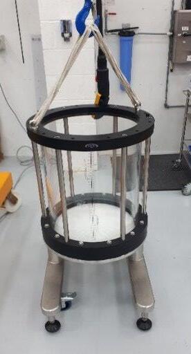
4. Identify the components on the schematic shown in Figure 1.
5. Using the correct spanners, remove and retain the column tube bottom flange bolts, washers and bolts
6. Lift the column tube unit, and when suspended, loosen the tie bar fixing bolts that are located in the bottom column flange.
7. Place the tube unit on a flat surface.
Tube Replacement Kit Installation Guide - Evolve® 350 mm Process Columns 4
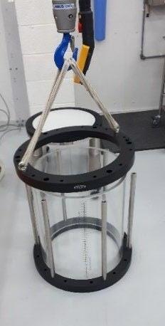
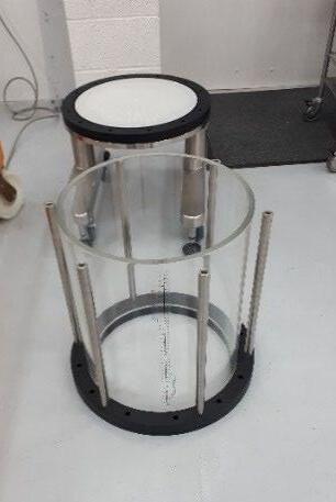
Figure 1 Column Tube unit
8. Remove and retain the tie bar fixing bolts from the top flange and remove the top flange.
9. Lift the tube out of the bottom tube flange. If the tube is difficult to remove from flange, ease the lower buffer seal out of its location.
Tube Replacement Kit Installation Guide - Evolve® 350 mm Process Columns 5
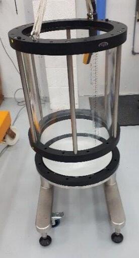
Figure 2 Removal of tube unit from Column Base
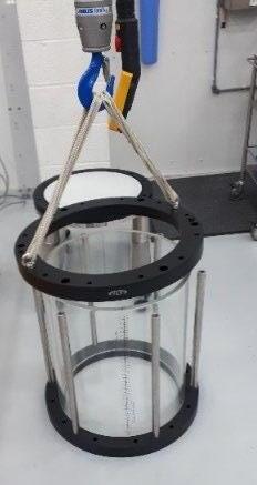
Figure 3 Dismantling of the Column Tube Unit
Replacement of Tube into Column
In the tube replacement kit, the tube unit is partially assembled and is supplied with scale label and buffer seals in position.
1. Remove all items from packaging.
2. If the tube support rods have been removed, turn bottom tube flange on its side to allow the attachment of the tube support rods using the correct bolts and Allen key.
3. When all rods are located and fixed in place, place the flange on a clean flat surface.
4. Locate the column tube seal into the groove in the flange.
5. Ensure the replacement tube is orientated correctly; the orientation of the tube is determined by the fitted scale label. The scale label on the tube should be aligned at right angles to the alignment indicator labels.
6. The buffer seals should be in position on the outside diameter of the tube at a distance approximately 2 cm from the end of the tube.
7. Locate the acrylic tube into the bottom column flange. Ensure it is located centrally and push down to ensure correctly seated. This is a two-person operation.
8. Lift the top column flange and place so that the tube support rod bolts can be engaged. Ensure alignment indicators are aligned.
9. Lower the top flange and secure the bolts by hand. Do not fully tighten the bolts.
10. Locate the upper and lower buffer seals into the bottom flange and underside of the top column flange.
11. Using the correct Allen key tighten the tube support rod bolts located in the top column flange. Use the torque wrench with a setting of 50 Nm is recommended.
Tube Replacement Kit Installation Guide - Evolve® 350 mm Process Columns 6
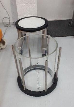
Figure 4 Reassembly of Column Tube Unit
12. Use the hoist to lift the tube unit and check the tube support rod bolts in the bottom flange and tighten if necessary.
13. Reassembly the column by fitting the fixed and adjuster assemblies as described in the operating manual.
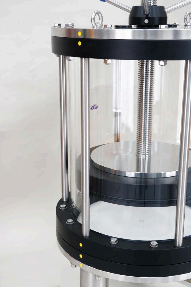
14. Alignment Indicators are located on the top flange, tube flanges, bottom flange and based plate. Use these to orientate the column components correctly
Alignment Indicators

After exchanging the tube and reassembly of the column it is advisable to perform a hydrostatic leak test before the column is used.
Tube Replacement Kit Installation Guide - Evolve® 350 mm Process Columns 7
Figure 5 Alignment Indicators on the Evolve® 350 Column
Hydrostatic Leak Test
The purpose of this test is to check that there are no leaks from the column and the column is ready to use. Due to the materials of fabrication, when the column is initially exposed to pressure, the column will flex. It is necessary to perform the hydrostatic leak test using a two-step procedure.
1. Fill the column with WFI or high quality water and position the adjuster at the operating bed height.
2. Ensure the adjuster seal is wetted with buffer or other suitable liquid prior to assembly. This helps ‘lubricate’ the seal to ensure correct seating.
3. Activate the adjuster seal
4. Ensure all air is removed from the column and any connections.
5. Attach a calibrated pressure gauge to the top inlet of the column
6. Raise the column pressure until 3 bar (45 psi) and close bottom inlet valve. Wait 15 minutes for the pressure to stabilize.
7. Open the valve and increase the pressure to maximum working pressure 4 bar (58 psi).
8. Wait 15 minutes for the pressure to stabilise. Check the pressure and ensure pressure is 4 bar (58 psi).
9. Wait for 15 minutes.
Due the nature of materials it is likely there will be a small pressure drop however, this should not exceed 0.1 bar.
Tube Replacement Kit Installation Guide - Evolve® 350 mm Process Columns 8
Contact Us
To view our Evolve® Column User guides please visit: https://www.astreabioseparations.com/resources/hardware- user-guides
For further enquires please contact: sales@astrea-bio.com
Tube Replacement Kit Installation Guide - Evolve® 350 mm Process Columns 9
Revision History
Revision
Comments Date
A Initial release 21/1/2021
B Updated to include Evolve® Registered trademark status 12/07/2021
C Addition of torque values 01/05/2023
D Rebranding 05/04/2024 Manual Revision Date D April 2024
Tube Replacement Kit Installation Guide - Evolve® 350 mm Process Columns 10

Issue Date: 05 April 2024 Author Name:
QA Reviewer Name: T
This product is covered by or for use under one or more patents: https://www.astreabioseparations.com/legal/patents/ All trademarks, trade names, trade dress, product names and logos are the property of Astrea UK Services Ltd. Copyright © 2023 Astrea Bioseparations Ltd. All rights reserved.
L Pepperell
Moore
