SOLAR POWER MONITORING – FIBER OPTIC SOLUTIONS FOR FIRE PREVENTION & PERIMETER SECURITY
Bandweaver’s FireLaser distributed temperature sensing (DTS) and fiber optic-based Perimeter Intrusions Detection Systems (PIDS) provide full protection for solar farms both from a fire prevention and security standpoint. This application notes details how the systems operate both from a fire detection perspective and a perimeter security solution.
FIRE PREVENTION
There are a number of risks to solar panels that can lead to overheating and a potential fire event. These risks include short circuits, poor installation (wrongly specified), faulty components (inverters & DC switches) and natural hazards (birds’ nests, foliage). With regards to traditional fire detection there are not many solutions available, and, in most cases, fires have been visually reported by passersby.

INTRODUCTION
Over the past decade the use of photovoltaic technology using solar panels for power generation has grown at a rate greater than 40% per year. Solar power is a truly renewable energy and is extremely versatile with the ability to be deployed on a small scale (residential housing roof tops) or on a large scale (industrial solar farms). The maintenance costs are relatively low with the main focus being on keeping the panel clean to maximise efficiency.
However, as with any system the operator must take into consideration both fire prevention and security considerations and Bandweaver’s fiber optic monitoring solutions can provide effective solutions in both areas.
Fiber optic LHD (Linear Heat Detection) systems can provide a very effective means of fire detection for solar panel installation as they have several key advantages.
• Fully distributed coverage. With measurement points every 1m along the full length of the cable every panel within the installation can be safely monitored by the fiber optic sensing cable.
• Smart alarms. With the advanced smart alarms, the system can detect fires much earlier than with conventional copper based LHD systems.
• Cost-effective installation. The sensing cable is based on standard telecoms cable and so no specific sensing points are required. This makes it extremely cost effective for system design and installation.
• Immune to electromagnetic interference. Fiber optics are not affected by electromagnetic interference and so will not be affected by the potentially high levels due to the power generation.
• High reliability. The fiber optics sensing cables are completely inert and not susceptible to corrosion and with no moving parts or apertures can last more than 50 years in certain environments.
INSTALLATION OF CABLE
Typically, the fiber optic sensing cable is installed at the rear of the panel.
The precise position depends on the specific type of solar panel, and it is typically secured to one of the panels mounting rails.
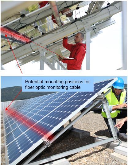
This maybe in the center of the panel (as shown in the diagram) or at the top of the panel.
The cable can be secured using simple cable clip or UV resistant cable ties.
 Figure1 -Exampleofsensingcablepositions
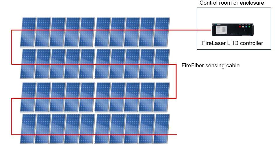
Each of the FireLaser LHD controllers can measure up to 10km on each sensing cable, with measurements every 1m. This means that a single controller can cover a large size solar power array. In this case the cable is typically run in continuous length throughout the entire array (as shown below).
With regards to the distributed nature of the measurement, with LHD systems the system provides a full temperature profile with points every metre along the length of the system. In traditional detection systems, if the seat of the fire does not happen to be immediately under a point type sensor, the fire can no longer be detected with certainty, mainly due to detector spacing. The FireLaser fire detection system does not have any such ‘gaps’, since the radiation heat given off by the fire is applied over the continuous length of sensing cable and is recorded and displayed accordingly.
SMART ALARMS & FULL COVERAGE
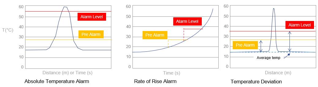
Two of the key advantages of fiber optic linear heat detection (LHD) systems are based on the smart alarming functionality and the distributed nature of the measurements. With fiber optic LHD systems based on DTS, three different types of alarms are configurable.
3
Figure2 -Exampleofcableconfigurationwithsolararray
Figure3-Smartalarmingwithfiberopticlinearheatdetectionsystems
SYSTEM INTEGRATION
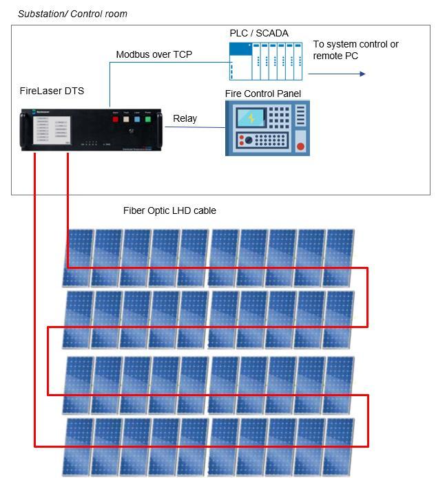
The fire detection system that incorporates a FireLaser DTS system recognises a fire and automatically actuates the relevant, preprogrammed protective measures (alarm signals, ventilation control, fire suppression etc.). The fire alarm system needs to provide information on the exact location of the fire and key data on fire development in order to bring the necessary rescue or fire-fighting measures into action systematically.
The Bandweaver FireLaser DTS linear heat detection system has a centrally located sensor control unit, which is able to determine the temperature at any position along the length of connected sensor cable. The sensor cable is fed through the assets to be protected, which may include ceiling and floor void spaces, switch rooms etc. The cable is divided via the software into multiple fire detection zones, where each zone can have its own unique characteristic alarm thresholds assigned to it, so the system is extremely flexible in this regard.
The location of the FireLaser controllers for an application is typically near the fire control panel. The FireLaser LHD comes with its own LCD screen and so can independently display the alarm events and also outputs to the fire alarm control panel.
4
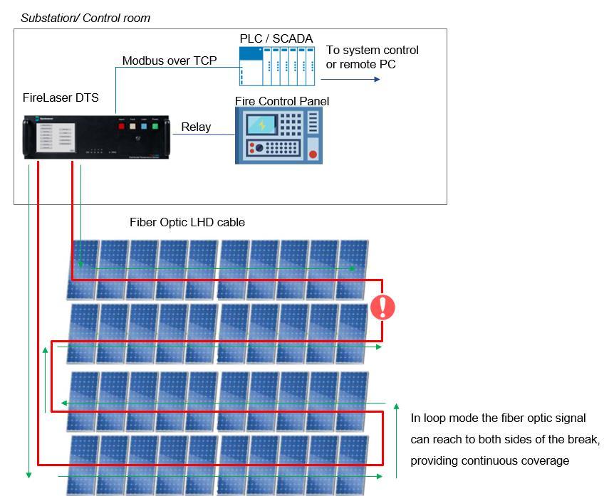
Figure4
-ExampleofSystemArchitecturewithloopconfiguration
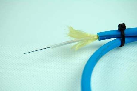
FIREFIBER LINEAR HEAT DETECTION CABLE
The sensing cable is a completely passive element and is based on standard fiber optic telecommunications fiber. For the fire industry, the standard fiber configuration has been using a 62.5/125 fiber optic due to its superior performance at distances up to 10km.
Because the sensing cable is made from fiber optic and is completely passive, it has the following benefits:
• Continuous coverage: No discrete sensors but continuous spatial measurements. The FireLaser provides measurement points every 50cm.
• Immune to electromagnetic interference: Can be used in areas of high electromagnetic activity without fear of affecting or being affected by other electrical equipment.
• Corrosion and vibration resistant: As the sensing element has no moving parts and is immune to corrosion, the cable has an extremely long lifetime and can be in excess of 30 years.
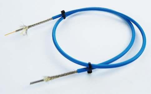
The FireFiber range of cables are designed to give maximum protection to the fiber optic while maintaining a thermal conduction, which can enable the system to react very quickly. It is also very lightweight and flexible, making it easy to install.
5
Figure5-ExamplesofFireFibercables
FIRE DETECTION - SYSTEM REDUNDANCY
Depending on the customer requirements, different levels of redundancy can be required. Essentially there are two key types of redundancy:
• Cable Redundancy: In the event of damage to the cable, the system can continue to function (although a system alarm will be generated so that action for repair, analysis can be taken).
• Controller Redundancy: In the event of a failure to one of the fiber optic LHD controllers, the system will continue to function.
For solar farms, it is unusual to have more than a single controller and so the redundancy provision is based around cable redundancy. The diagram below outlines the principle:
6
Figure6 -Loopredundancyexample
SECURITY – INTRUSION DETECTION
Solar farms, just like agricultural farms, are often set in rural, isolated areas with no personnel or passers-by from the community at night or off-peak times, Increasingly, these are becoming a target for thieves. In addition to the panels and batteries plant, cabling and inverters can also provide enough resale value to make them a target for theft.
In addition to losses due to theft, cost of damage and repair as well as loss of income represent a real threat to the operator. Even just one set of cells being stolen can significantly reduce power output and revenue.
One of the first lines of defence for solar farms is the perimeter and Bandweaver has several fiber optic based PIDS systems (Perimeter Intrusion Detection Systems) ranging from hundreds of m’s to 100km per system.
Perimeters for solar farms are often quite large (>1km) and of irregular shape where a single security technology cannot cover all aspects. Fiber optic based PIDS can be an ideal solution or complement to other technologies (e.g. CCTV, beam detectors etc.) for a perimeter security solution.

Fiber optic based PIDS have several unique advantages over traditional security technology solutions including the following:
• Consistent detection over long distances – up to 50km per channel.
• Highly sensitive detection – producing excellent acoustic signal gathering.
• Leading location accuracy – identifying an intrusion down to 1 metre.
• Suitable for both fence/wall mounted and buried applications
7
Figure7 -Exampleofsolarfarmperimeter
BANDWEAVER PIDS SOLUTIONS
Bandweaver has a range of fiber optic based PIDS solutions depending on the specifics of the particular site. Below is a summary table detailing the overview of the specifications of the different products.
SECURITY SYSTEM - CUT RESISTANCE
The below diagram shows a resilient design to maintain detection capability in the event of a fiber cable cut or damage with only one cable required but two fiber cores and two channels required - one core monitoring clockwise and one core monitoring anti-clockwise.

8
Bandweaver Product Range per optical channel Technology Number of zones Positional accuracy Buried or fence/wall mounted Cut Resistance Intrusion classification ZoneSentry 1km Zone based interferometer 4 or 8 Within zone Fence/wall No Detection only FenceSentry 5km COTDR/DAS 1000 1-5m Fence/wall Yes Detection only Horizon 50km COTDR/DAS 1000 1-5m Both Yes -Personnel -Vehicle -Manual dig -Excavator -(moreavailableon request)
Table1 -ComparisonofBandweaverPIDSsystems
Figure8 -Cutresistantconfiguration
HOW IT WORKS
The DAS Detection Unit (DU) sends an encoded light signal down a standard single mode fiber cable, this light will reflect back to the DU from micro imperfections in the side of the glass fiber (referred to as Rayleigh backscatter). When the cable is exposed to vibration the characteristics of the backscatter changes and the DAS PU analyses these changes against advanced algorithms. If a pattern is recognized an alarm event will be generated and a location will be identified based upon the length of time the light took to reflect back to the DU.


The DU will typically sample points every 1 metre down along the fiber
9
Figure9 -Simplicityofmeasurement
Figure10 –RepresentationofRayleighbackscatter
Figure11–Compositionoffiberopticcable
optic cable.
FENCE/WALL MOUNTED CABLE

The cable will be attached to the fence in a straight-line run using outside grade UV resistant cable ties as per the diagram on the left below and in a loop pattern on a gate as per the diagram on the right below.

BURIED/COVERT CABLES

For buried detection, the cable can be installed at a depth of around 40-60 cm. This ensures reliable detection in most soil conditions whilst still providing a covert solution that will survive most environmental conditions. The cable can be buried in either in a straight run pattern or a serpentine pattern dependent on the performance requirements, the serpentine pattern gives greater detection capability to detect crawling, planking, etc.


10
Figure12 -Fencemounteddetection –patterns
Figure13-Covertburieddetection –patterns
Note:Exactdetection capabilityisdependent oncabledepth,soil typeetc.whenthe systemissetupfor minimalnuisance alarms.
Notes:
• Trenchcanbedugeitherbyhandorbymechanicaldigging.
• Dependentonsoiltype,addinganadditionallayerofuniformcrushedgravelorsimilaraggregateontopoftheopticalfibercable providesgoodvibrationtransmission,especiallyinlooseorsandysoilconditions.
Landscapemaintenanceshouldbeundertakentoensurethatthecabledepthdoesnotexceed50cminoperationalconditions
DETECTION ALGORITHMS

Fiber optic based PIDS utilise advanced machine learning to process signals to ensure a high probability of detection whilst reducing the risk of nuisance alarms. These can include pattern recognition, artificial intelligence, Deep Neural Networks (DNN), and Recurrent Neural Network (RNN) amongst others.
The raw data is processed via advanced environmental algorithms, which can differentiate between environmental noise and real intrusion events as demonstrated below.
Utilising the latest generation machine learning ensures that the PIDS solution will still detect an intrusion event even during the worst weather conditions, ensuring operator confidence remains high.

11
Figure14-Covertburieddetection
–
detectionprobabilityistypically95%+
Without environmental correction algorithm With environmental correction algorithm Real intrusion event Vibrations caused by high winds
COMPARISON OF DIFFERENT PIDS SOLUTIONS


There are many different types of PIDS technology on the market, the table below shows a comparison on the most common type of detection. Some technologies are more suited to shorter range perimeters.
Table2 -ComparisonofPIDStechnologies
The above table demonstrates that the selection of technology must be carefully considered. As you will see from the first two columns fiber optic cable detection has an excellent resilience to nuisance alarms while having a low installation cost together with low ongoing maintenance costs with exceptional whole life value.

12
Fence/wall Fiber Optic Cable (DAS) Buried Fiber Optic Cable (DAS) Radar Active Infrared Electric fence Microwave CCTV Video Motion Detection Thermal Imaging Cameras Line of sight detection required No No Yes Yes No Yes Yes Yes HSE risk No No No No High No No No Suitable for intrinsically safe sites Yes Yes No No No No No No Affected by fog, heavy rain Low None Low High Low Low Medium Low Impacted by changes in terrain No No Yes Yes No Yes No No Requires power in field No No Yes Yes Yes Yes Yes Yes Impacted by vegetation/foliage No No Yes Yes No No Yes No Installation & Commissioning Simple Simple Complex Simple HSERisk Medium Medium Medium Maintenance Requirements Low Low High Medium Medium Medium High High Life span of detection sensor Typically 25+years Typically 25+years Typically 3-5years Typically 3-5years Typically 3-5years Typically 3-5years Typically 3-5years Typically 3-5years Suitable for long range perimeters Yes Yes Multiple Units No No Multiple units Multiple Units Multiple Units Infrastructure Investment Costs Low Low High High Medium High High High System affected by EMI/RFI No No Yes Yes No Yes Potential Potential System triggered by animals Low Low Low High Low Medium High Medium System affected by rivers/water No No Yes No No Yes No No Installed Cost Low Low High Low Low High High High Whole Life Costs Low Low High Medium Medium High High High
INTEGRATION WITH WIDER SECURITY SYSTEM
A PIDS solution will usually be deployed as part of a wider site risk mitigation solution alongside other sub-systems such as CCTV, access control, screening and scanning equipment, etc. It is therefore vital that the PIDS solution fully integrates into any command-and-control system, whether a PSIM, VMS, SMS, etc.
Bandweaver systems are extremely versatile and can operate as a standalone system or can integrate within a wider VMS/PSIM/BMS system. Bandweaver has an additional integration software platform MaxView.

For integration with 3rd party systems MaxView is extremely versatile and typically operates in one of two different configurations:
1. MaxView export to PSIM/VMS/BMS: In this scenario, MaxView will output the alarm information to the format of the 3rd party PSIM/VMS/BMS. The information will typically contain information about the specific alarm, (e.g., alarm type, priority, time, geographical/zone information.
2. MaxView import of 3rd party sensors/CCTV: In this scenario MaxView operates as the main interface and can bring in 3rd party sensors (e.g. beam sensors for gate access) or CCTV feeds, which can then be automatically cued to slew to the appropriate location in the event of an alarm.
13
Figure15-BandweaverintegrationwithinsecuritysystemusingMaxView
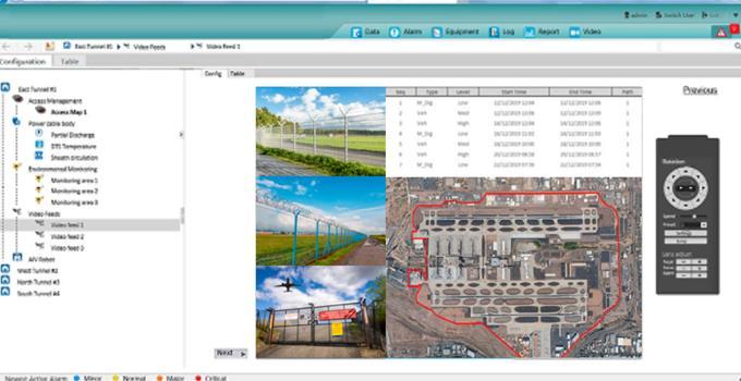
GRAPHICAL USER INTERFACE
Typically, the PIDS solution will be connected to a central server, which will act as the human machine interface (HMI) where the operator can see a map view of their site and any alerts or alarms similar to the screenshot below.

The GUI will display in real time any intrusion alerts together with the exact location on a map with GPS coordinates and where connected the feed form the most relevant CCTV camera, this ensure that the operator has all relevant information at their disposal to affect an appropriate response.
ABOUT BANDWEAVER TECHNOLOGIES
Bandweaver has been providing advanced fiber optic monitoring sensors and integrated technologies since 2002. With an installed base of over 30,000km and 3,500 systems installed, our knowledge regarding the application of distributed temperature sensing technology and linear heat detection within the fire industry is second to none.
We focus on the integration of fiber optic based technologies into clients’ proprietary systems and Bandweaver and our partner SenseTek Fire & Security Solutions In the Netherlands, provide exceptional systems design support, product support during installation and provide long term maintenance packages.
For further information please contact SenseTek Amsterdam at sales@sensetek.nl
14
Fig16 – SoftwareInterfaceexample
SenseTek Fire & Security Solutions Abberdaan 162 │1046 AB │ Amsterdam T: +31(0)20 6131611 │ F: +31(0)20 6132212 www.sensetek.nl info@sensetek.nl
