
Practical Electronics Crash Course


Learning circuit design the fun way


 Dogan Ibrahim Ahmet Ibrahim
Practical Electronics Crash Course
Learning circuit design the fun way
●
Dr. Dogan Ibrahim Ahmet Ibrahim● This is an Elektor Publication. Elektor is the media brand of Elektor International Media B.V.
PO Box 11, NL-6114-ZG Susteren, The Netherlands
Phone: +31 46 4389444
● All rights reserved. No part of this book may be reproduced in any material form, including photocopying, or storing in any medium by electronic means and whether or not transiently or incidentally to some other use of this publication, without the written permission of the copyright holder except in accordance with the provisions of the Copyright Designs and Patents Act 1988 or under the terms of a licence issued by the Copyright Licencing Agency Ltd., 90 Tottenham Court Road, London, England W1P 9HE. Applications for the copyright holder's permission to reproduce any part of the publication should be addressed to the publishers.
● Declaration
The authors and publisher have used their best efforts in ensuring the correctness of the information contained in this book. They do not assume, or hereby disclaim, any liability to any party for any loss or damage caused by errors or omissions in this book, whether such errors or omissions result from negligence, accident or any other cause.
● British Library Cataloguing in Publication Data
A catalogue record for this book is available from the British Library
● ISBN 978-3-89576-605-3 Print
ISBN 978-3-89576-606-0 eBook
● © Copyright 2024 Elektor International Media www.elektor.com
Editor: Clemens Valens
Prepress Production: D-Vision, Julian van den Berg
Printers: Ipskamp, Enschede, The Netherlands
Elektor is the world's leading source of essential technical information and electronics products for pro engineers, electronics designers, and the companies seeking to engage them. Each day, our international team develops and delivers high-quality content - via a variety of media channels (including magazines, video, digital media, and social media) in several languages - relating to electronics design and DIY electronics. www.elektormagazine.com
● 4
2.2.5
2.3.3
Contents ● 5 Contents Preface ........................................................... 12 Chapter 1 • Electricity ............................................... 13 1.1 Overview .................................................... 13 1.2 What is Electricity? ............................................. 13 1.3 Electronic Circuits .............................................. 14 1.4 DC and AC ................................................... 14 1.5 Electric Power ................................................. 16 1.6 Basic Lamp/Switch Circuits ........................................ 17 1.6.1 One Switch Only .............................................. 17 1.6.2 More Than One Switch.......................................... 18 1.6.3 Two-Way Switch .............................................. 19 Chapter 2 • Passive Components ....................................... 20 2.1 Overview .................................................... 20 2.2 Resistors .................................................... 20 2.2.1 Types of Resistors ............................................. 21 2.2.2 Resistive Materials ............................................ 23
Resistor Specifications .......................................... 24
Resistor Colour Code ........................................... 24
2.2.3
2.2.4
Ohm’s Law .................................................. 27
Resistors in Series and Parallel ................................... 27 2.2.6 Resistors in Electrical Circuits - Examples ............................ 28 2.2.7 Voltage Divider Circuit 30 2.2.8 Other Types of Resistors 32 2.2.9 Project 1 – Resistor Circuit 33 2.2.10 Using a Circuit Simulation Program 35 2.3 Capacitors 37
Types of Capacitors 38
Capacitor Values 39
2.2.6
2.3.1
2.3.2
Capacitor Value Marking 39
Capacitors in Series and Parallel 40
2.3.4
Practical Electronics Crash Course ● 6 2.4 Inductors 42 2.4.1 Types of Inductors 42 2.4.2 Inductor Values 43 2.4.3 Inductor Markings 43 2.4.4 Inductors in Series and Parallel 45 2.4.5 Mutual Inductance 46 2.5 A Simple RC Network 46 2.5.1 Project 2 – Resistor-Capacitor Transient Response 49 2.6 Resistor-Capacitor-Inductor Circuit Transient Response 51 2.7 Resistance Versus Impedance 53 Chapter 3 • Magnetics ............................................... 55 3.1 Overview .................................................... 55 3.2 Magnets in Electronics ........................................... 55 3.3 Electromagnets ................................................ 55 3.4 The Reed Switch ............................................... 56 3.5 Loudspeakers ................................................. 57 3.6 Transformers ................................................. 58 3.7 Relays ...................................................... 61 Chapter 4 • Active Components ........................................ 64 4.1 Overview .................................................... 64 4.2 Semiconductor Diodes ........................................... 64 4.2.1 Diode Types ................................................. 65 4.2.2 Diode Circuits ................................................ 71 4.2.2.1 Simple LED Circuit ........................................... 71 4.2.2.2 Project 1 – LED With Push-Button ................................ 72 4.2.2.3 Project 2 – RGB LED With Push-Buttons ............................ 73
Project 3 – Zener Diode Regulator ................................ 75
Rectifier Circuits............................................. 78 4.3 Bipolar Transistors .............................................. 83 4.3.1 DC Voltages and Currents in a Transistor ............................. 84 4.3.2 Common Emitter Amplifier ....................................... 86
4.2.2.4
4.2.2.5
5.6.1
Contents ● 7
Transistor as a Switch 90 4.3.3.1 Project 4 – Transistor Switch With LED 92 4.3.4 MOSFET as a Switch 94 4.3.4.1 Project 5 – MOSFET Switch With LED 96 4.3.4.2 Project 6 – Steady Hand Game 98 Chapter 5 • Simple Circuits Based on Previous Chapters ................... 101 5.1 Overview 101 5.2 Mechanical Switches 101 5.2.1 Project 1 – Upstairs-Downstairs Two-Way Switch 105 5.2.2 Contact Bounce Problems 106 5.3 Project 2 – Relay With LED ....................................... 106 5.4 Electronic Buzzers ............................................. 107 5.5 Optocouplers................................................. 108 5.5.1 Example Optocoupler Circuit .................................... 109
Transistor Oscillators and Other Circuits .............................. 109
4.3.3
5.6
Sine Wave Transistor Oscillators .................................. 109
The Multivibrator ............................................ 114
Project 3 – Astable Multivibrator Flashing LEDs ...................... 116 5.6.2.2 Project 4 – Monostable Multivibrator Timed LED ..................... 118 5.7 The 555 Timer................................................ 119 5.7.1 Project 5 – Blinking an LED With the 555 ............................ 120
Project 6 – Alternating LEDs..................................... 123
Project 7 – 1 kHz Buzzer ....................................... 124
Project 8 – Continuity Tester .................................... 126
Project 9 – Alarm with Three Sounds............................... 127 5.7.6 Project 10 – Mosquito Repeller ................................... 129 5.7.7 Project 11 – Darkness Detector .................................. 130 5.7.8 Project 12 – Metronome ....................................... 132 5.7.9 Project 13 – LED Timer ........................................ 134 5.7.10 Project 14 – Outside Light with Long Delay ......................... 136
Project 15 – Improved Metronome ............................... 137
5.6.2
5.6.2.1
5.7.2
5.7.3
5.7.4
5.7.5
5.7.11
Practical Electronics Crash Course ● 8 5.7.13 The Bistable 555 138 5.8 Project 15 – Two-Transistor Blinky 139 5.9 Fixed-Output Voltage Regulator ICs 140 5.10 Reverse Polarity Protection 141 Chapter 6 • Operational Amplifiers .................................... 143 6.1 Overview 143 6.2 Operational Amplifier Structure 143 6.3 Inverting Amplifier 144 6.4 Noninverting Amplifier 146 6.5 Voltage Follower 147 6.6 Summing Amplifier ............................................ 147 6.7 Difference Amplifier ............................................ 148 6.8 Integrator ................................................... 149 6.9 Differentiator ................................................ 150 6.10 Comparator................................................. 150 6.11 Summing Amplifier Simulation ................................... 151 6.12 Project 1 – Comparator With LED.................................. 152 Chapter 7 • Logic Gates ............................................. 155 7.1 Overview ................................................... 155 7.2 Commonly Used Logic Gates ...................................... 155 7.2.1 AND Gate ................................................. 155 7.2.2 OR Gate .................................................. 155 7.2.3 NOT Gate .................................................. 156 7.2.4 NAND Gate ................................................ 156 7.2.5 NOR Gate ................................................. 156 7.2.6 XOR gate .................................................. 157 7.2.7 XNOR Gate ................................................ 157 7.3 Logic Gate IC Families .......................................... 157 7.3.1 Mixing Different Logic Families ................................... 159 7.4 Project 1 – AND Gate with LED and Push-buttons ....................... 162 7.5 Diode Logic .................................................. 163
7.5.1
7.6
7.7
7.8
7.9
8.2.6
8.5.1
8.5.2
Contents ● 9
Diode OR Gate 163
Diode AND Gate 164 7.5.3 Mixed Diode AND & OR Gate 164 7.5.4 Diode Logic vs. Digital Logic 165
Single-Gate Logic Devices 165
7.5.2
7.5.5
Flip-Flops 165
Counters 167
The 74595 Shift Register 170
What is an FPGA? 172 Chapter 8 • Advanced Subjects ....................................... 174 8.1 Overview ................................................... 174 8.2 Alternating Current (AC) Analysis .................................. 174 8.2.1 Root Mean Square (RMS) ....................................... 175 8.2.2 Resistors and AC............................................. 175 8.2.3 Inductors and AC ............................................ 175
Capacitors and AC ........................................... 176
RLC Circuit and Resonance ...................................... 176
8.2.4
8.2.5
Power in AC circuits .......................................... 180 8.3 Amplifiers ................................................... 181 8.3.1 Amplifier Gain .............................................. 181 8.3.2 The LM386 Amplifier .......................................... 183 8.3.3 The TDA2030 ............................................... 185 8.4 Oscillators .................................................. 186 8.4.1 Phase-Shift Sine Wave Oscillator.................................. 186 8.4.2 Square Wave Oscillator ........................................ 187
Filters ..................................................... 188
8.5
Filter Roll-Off and Filter Order ................................... 189
Filter Design Program ......................................... 190
Low-Pass Active Filters ........................................ 190 8.5.4 High-Pass Active Filters ........................................ 192 8.5.5 Band-Pass Active Filters........................................ 193
8.5.3
Practical Electronics Crash Course ● 10 8.5.6 Passive Low-Pass Filter 195 8.6 Sensors 196 8.6.1 Temperature Sensors 198 8.6.2 Force Sensors 203 8.6.3 Light Sensors 204 8.6.4 Sound Sensors 204 8.6.5 Acceleration Sensors 205
Soil Moisture Sensors 205
Distance Sensors 206 8.7 Switched-Mode Power Supply (SMPS) 206 8.7.1 The LM2576 Buck Converter .................................... 207 8.7.2 The LM2577 Boost Converter .................................... 207 8.8 Interesting Electronic Kits ........................................ 208 Chapter 9 • Test and Measurement .................................... 210 9.1 Overview ................................................... 210 9.2 Power Supplies ............................................... 210 9.2.1 Fixed or Variable Voltage ....................................... 210 9.2.2 Number of Output Channels ..................................... 210 9.2.3 Current Capacity............................................. 211 9.2.4 Current Limiting ............................................. 211 9.3 Multimeter .................................................. 211 9.3.1 Parts of a Multimeter .......................................... 212 9.3.2 Voltage Measurement ......................................... 213 9.3.3 Current Measurement ......................................... 214 9.3.4 Resistance Measurement ....................................... 215 9.4 The Oscilloscope .............................................. 215 9.4.1 Specifications ............................................... 216 9.4.2 Using the Oscilloscope ......................................... 217 9.5 Function Generators............................................ 218 9.6 Other Tools .................................................. 218 9.6.1 Soldering Iron .............................................. 219
8.6.6
8.6.7
Contents ● 11 9.6.2 Desoldering Pump 219 9.6.3 Miscellaneous Tools 219 9.6.4 Breadboard With Built-In Power Supply 220 9.6.5 Budget Tool Kits 220 Chapter 10 • Microcontroller Boards and MCU Programming ................ 222 10.1 Overview 222 10.2 Microcontroller Boards & Modules 222 10.3 The Arduino UNO R4 223 10.3.1 Project 1 – Blink an External LED 227 10.4 The ESP32-DevKitC 231 10.4.1 Project 2 – Blinking an LED With the ESP32 .......................... 234 10.5 The Raspberry Pi Pico .......................................... 237 10.5.1 Pinouts of the RP2040 and the Pico ............................... 238 10.5.2 Pico Programming ........................................... 239 10.5.3 Project 3 – Blinking an LED With MicroPython ........................ 243 10.6 The Raspberry Pi ............................................. 246 10.6.1 Installing the Raspberry Pi Operating System ........................ 247 10.6.2 Project 4 – Blinking an LED With a Raspberry Pi ....................... 253 Chapter 11 • Other Topics of Interest .................................. 257 11.1 Overview .................................................. 257 11.2 Component Selection .......................................... 257 11.3 Reading a Datasheet .......................................... 258 11.4 Schematic Capture and PCB Design ................................ 262 11.5 EMC and EMI ................................................ 266 11.6 Norms and Regulations ......................................... 267 Appendix – List of Components Used in Projects .......................... 269 Index ........................................................... 270
Preface
Welcome to the world of electronics!
In this beginner-friendly book, you will explore and learn the most important electrical engineering and electronics concepts in a fun way by doing various experiments and by simulating circuits. The aim of the book is to teach you the basic electronics without getting into complex technical jargon and calculations.
Learning electronics is not as difficult as it may seem. Using this book, you will be creating your own projects sooner than you might think. The book starts from the very basics, such as what is electricity? What is voltage? What is current? and so on. You will then learn about simple electronic circuits and the symbols used in circuits. No previous knowledge of electronics is required, only some simple algebra is required to be able to make simple calculations. Circuit simulation has been introduced at an early stage to enable readers to experiment with different circuits.
You will learn:
• The concepts of voltage, current, circuit, and power
• AC and DC voltages
• Basic lamp circuits with switches
• Resistors, capacitors, inductors and how to identify them
• Transient circuits
• Electromagnetism
• Loudspeakers, reed switches, and transformers
• Diodes, BJT and MOSFET transistors and switching circuits
• Optocoupler circuits
• Multivibrator and astable/monostable circuits
• Using the 555 chip
• Operational amplifiers and various circuit configurations
• Logic gates
• Amplifiers, oscillators, and electrical filters
• Sensors
• Electrical test and measurement tools
• Microcontroller development boards: Arduino Uno, ESP32, Raspberry Pi Pico, and Raspberry Pi 5
• Electronic component selection and reading data sheets
• Electrical EMC and EMI and norms and regulations
Many tested and working projects and simulations are given in the book to make you familiar with the construction and testing of the basic electronic circuits given in the book. I hope you enjoy reading the book.
Dr. Dogan Ibrahim, BSc., MSc., PhD Ahmet Ibrahim, BSc., MSc London, 2024Practical Electronics Crash Course ● 12
Chapter 1 • Electricity
1.1
Overview
We all use electricity in our daily lives, and we cannot do without it. Can you imagine what will happen if electricity was not available for a few days? Imagine life with no heating, no lighting, no radio, no TV, no internet, no computer, no microwave, no fridge… But have you ever asked yourself: What is electricity? What is voltage? What is an electrical circuit? How can I connect lamps in different ways? The aim of this chapter is to answer these questions in detail.
1.2 What is Electricity?
Atoms are the building blocks of matter; they are the smallest units of matter that have the chemical properties of a given substance. Atoms comprise three basic components: protons, neutrons, and electrons (Figure 1.1). The protons and neutrons are in the center of the atom, known as the nucleus, while the electrons orbit at a considerable distance from the nucleus.

The atomic number of an atom corresponds to the number of protons in the nucleus. For example, a carbon atom has six protons in its nucleus, therefore its atomic number is six. The sum of the number of protons and neutrons determine the atomic mass of an atom.
Protons are positively charged particles inside the nucleus. The neutrons inside the nucleus do not have charge. The mass of a neutron is more than that of a proton. Electrons are negatively charged particles that orbit the nucleus within orbital shells. They are much smaller than protons and neutrons. The overall charge of an atom is determined by the difference between the number of protons and electrons. For example, if there are more protons than electrons, the net charge is positive. If the number of protons is equal to the number of electrons, the net charge is zero.
Electricity is the set of physical phenomena associated with the presence and motion of electric charge. Electrons can flow only if there are free electrons in a substance. Concerning the flow of electrons, materials fall into three categories:
Chapter 1 • Electricity ● 13
Figure 1.1 An atom. (source: www.vedantu.com)
Insulators: Some materials like wood, paper, plastic, rubber, etc. do not conduct electricity and therefore are good insulators. This is due to the (very) low number of free electrons that are available.
Conductors: Many metals such as copper, iron, silver, steel, etc. are excellent conductors of electricity. This is because they have an abundance of free electrons.
Semiconductors: Materials like germanium, arsenic, boron, and silicon have only a few free electrons. They conduct electricity better than insulators but not as good as conductors do. Semiconductors are used for manufacturing transistors and integrated circuits (ICs).
1.3 Electronic Circuits
For electrons to flow, an electronic (or electrical) circuit is required. A circuit is a closed loop of conducting material such as wire. Of course, every electronic circuit also contains components, but there may not be insulators in the circuit loop. The electrons in an electronic circuit do not move unless they are forced to do so. This force can be a battery or any other type of energy source connected to the circuit. The movement of electrons in a circuit constitutes the current in the circuit. Thus, when a voltage source is applied to a circuit, current can flow through it. The electrons flow from the negative pole towards the positive pole. But, because electrons have a negative charge, it is customary to say that the current flows from plus to minus.
The unit of voltage is volt, denoted by V (sometimes also denoted by U). The unit of current is ampere, A. In most electronic applications, smaller units of volt and ampere may be used. The conversions to smaller units are as follows:
1 V = 1,000 millivolt (1000 mV)
1 mV = 1,000 microvolt (1000 μV)
Similarly,
1 A = 1,000 milliampere (1000 mA)
1 mA = 1,000 microampere (1000 μA)
1.4 DC and AC
There are two types of voltage sources: Direct Current or DC and Alternating Current or AC.
DC
In a DC circuit, the current always flows in the same direction. A DC voltage source does not necessarily have a constant value, but it never changes sign. An example of a DC voltage source is an ideal battery, which provides a constant voltage over time. For example, an ideal PP-3 type battery provides 9 V as shown in Figure 1.2. This is described mathematically as:
V(t) = 9 V
Practical Electronics Crash Course ● 14

Of course, a battery loses its charge over time and its voltage drops as the battery is used, but for the discussion here, we assume that the voltage is constant.
AC
In an AC circuit, the direction of the charge flow and hence the voltage level reverses periodically. Electricity providers supply AC voltages known as the mains voltage to buildings all over the country. However, most electronic devices like mobile phones, computers, radios, TVs, etc. operate with DC voltages and the AC voltage must be converted into DC. As an example, your mobile phone has a battery and operates from a DC voltage, but you plug its charger into an AC wall socket. The charger converts the AC to DC to charge your phone’s battery.
AC voltages can have many shapes like sine, square, triangle, sawtooth, etc. The AC voltage supplied by electricity providers is in the form of a sine wave (Figure 1.3), expressed mathematically as:
V(t) = Vp sin(ωt) where
V(t) is the voltage as a function of time.
Vp is the amplitude (peak value) of the waveform. The waveform spans from −Vp to +Vp.
ω is the radian frequency equal to 2πf, where f is the frequency of the waveform in hertz.
t is the time in seconds.

1.3
Chapter 1 • Electricity ● 15
Figure 1.2 9V battery voltage.
Figure
Sine waveform.
The period of a sine wave is the time it takes for a cycle to complete and is related to the frequency by the relationship
T = 1/f
Example
Find the period and hence the frequency of the sine wave shown in Figure 1.4. Write down the mathematical expression of the waveform.

Figure 1.4 Example sine wave.
Solution
The amplitude is 10 V. The period of the waveform is found to be T = 2 seconds. Therefore, the frequency is f = 1/2 = 0.5 Hz. The radian frequency is, ω = 2πf = 2 × 3.14 × 0.5 = 3.14 rad/s. The mathematical expression of the waveform therefore is:
V(t) = 10 sin(3.14t)
1.5 Electric Power
Electric power is the rate at which electrical energy is transferred by an electric circuit. In other words, it is the rate of work done per unit of time by an electric circuit. The unit of electric power (P) is watt (W), given by:
P = current × voltage
Where power is in watt, current is in ampere, and voltage is in volt. Power is sometimes expressed in bigger or smaller units, as follows:
1 kW = 1,000 watt (1000 W)
1 W = 1,000 milliwatt (1000 mW)
1 mW = 1,000 microwatt (1000 μW)
Power can also be calculated from the energy in joule over a period of time. i.e.
P in W = energy/second = joule/second
Practical Electronics Crash Course ● 16
Example
A mains operated kettle works with 230 V and consumes 2 A. Find the power consumed by this kettle. If the kettle is operated for 10 seconds, how much electrical energy is used?
Solution
From the above equation, P = 230 × 2 = 460 W. The energy used is E = P × t = 460 × 10 = 4,600 joules.
1.6 Basic Lamp/Switch Circuits
Suppose you have some lamps and a few switches. Let us investigate in how many ways you can connect them in a circuit. In the following circuits, VLn is the voltage across lamp n, and ILn is the current through lamp n. Also, it is assumed that the brightness of the lamps is the same as long as current passes through them.
1.6.1 One Switch Only
Series connection of lamps
Figure 1.5 shows a series connection of three lamps and a switch. Here, the same current goes through each lamp. The sum of the voltages across each lamp is equal to the applied voltage. When the switch is closed, all lamps turn on.

Figure 1.5 Series connection. The same current flows through all the lamps. When the switch is closed, all lamps turn on. V = VL1 + VL2 + VL3
Parallel connection of lamps
Figure 1.6 shows a parallel connection of three lamps and a switch. Here, the same voltage is across each lamp. The sum of the currents through the lamps is equal to the main current. When the switch is closed, all lamps turn on.

Figure 1.6 Parallel connection. Each lamp has the same voltage across it. When the switch is closed, all lamps turn on. I = IL1 + IL2 + IL3
Chapter
Electricity ● 17
1 •
Series and parallel connection of lamps
Figure 1.7 shows a mixed series and parallel connection of three lamps and a switch. Here, the same voltage is across L2 and L3. The sum of voltages across L1 and L2 (or L3) is equal to the applied voltage. The current through L1 is equal to the sum of the currents through L2 and L3.
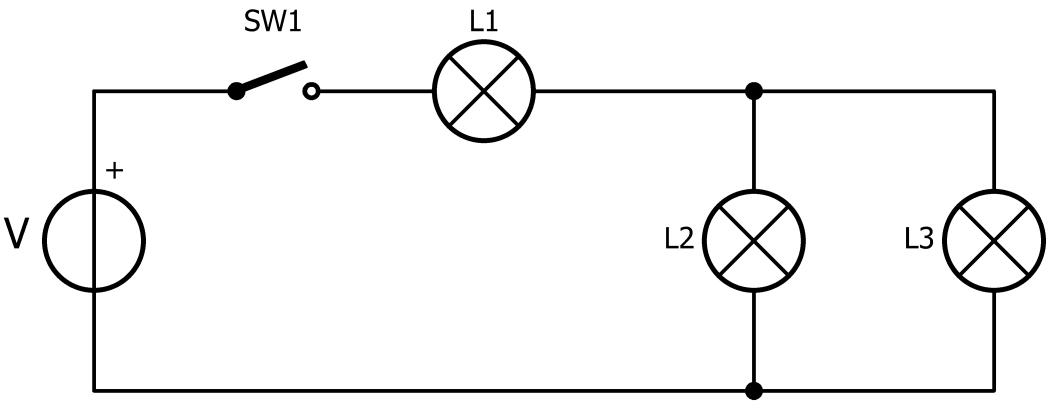
Figure 1.7 Series and parallel connection. Lamps L2 and L3 have the same voltage across them. When the switch is closed, all lamps turn on. V = VL1 + VL2 or V = VL1 + VL3; IL1 = IL2 + IL3
1.6.2 More Than One Switch
Figures 1.8 to 1.10 show various configurations of lamps and switches. The operation of each circuit is described below the circuits.

Figure 1.8 L1 and L2 turn on when SW1 is closed. L3 turns on when SW2 is closed.

Figure 1.9 L1 turns on when SW1 is closed and also SW2 or SW3 are closed.
L2 turns on when SW1 and SW2 are closed (L1 turns on too).
L3 turns on when SW1 and SW3 are closed (L1 turns on too).
All lamps turn on when all switches are closed.
Practical Electronics Crash Course ● 18
Chapter 1 • Electricity

Figure 1.10 L1 and L4 turn on when SW1 is closed. L2 turns on when SW1 and SW2 are closed (L1 and L4 turn on too). L3 turns on when SW1 and SW3 are closed (L1 and L4 turn on too).
All lamps turn on when all switches are closed.
1.6.3 Two-Way Switch
You are probably familiar with two-way switches if your home has a staircase or a long hallway. They are also often found in bedrooms. In a two-way switch configuration, a lamp is controlled by two switches, for example one downstairs and one upstairs. If the lamp is off, it can be turned on from the downstairs switch. Once you are upstairs, you can turn it off from the upstairs switch and vice versa. Figure 1.11 shows the schematic of a twoway switch. This circuit uses two switches of type SPDT (Single Pole Double Throw). The operation of various switches is discussed in Chapter 5.

Figure 1.11 Two-way switch. When the lamp is on, you can turn it off with either SW1 or SW2. When the lamp is off, you can turn it on with either SW1 or SW2.
● 19
Chapter 2 • Passive Components
2.1 Overview
Passive components are parts like resistors, capacitors, inductors, cables, switches, fans, lamps, antennas, terminals and connectors, coils, transformers, printed circuit boards (PCBs) and so on. These components cannot generate power, but they receive electrical energy, which they can either absorb, dissipate, or store. Passive components do not provide any gain or amplification of electrical signals. They can either be used on their own or connected in series or in parallel with other components in electrical circuits to control the current flow, apply a phase shift to signals, change the voltage across a component and so on. Passive components are bidirectional (they do not have polarity) as they can be connected in either direction within a circuit (except for electrolytic capacitors as they have polarity).
In this chapter, we will be looking at the most commonly used passive components: resistors, capacitors, and inductors, and their combinations in electrical circuits.
2.2 Resistors
Resistors play a crucial role in electrical circuits by impeding the flow of electric current. To comprehend the function of a resistor more easily, one can draw an analogy between electric current and water flowing in a pipe. In this analogy, a resistor is akin to a constriction in the pipe, acting to limit the flow of water through it. The degree of restriction in the pipe correlates with the resistance in the electrical circuit. Simply put, the higher the resistance, the more constrained the flow of electric current becomes. Similarly, in the water analogy, an increased constriction in the pipe results in a reduced volume of water able to pass through.
Resistors have many functions in electrical circuits. Some common uses of resistors are:
• Potential dividers: two or more resistors in series are used to reduce an input voltage to a required level.
• Current limiting: a resistor is used to limit the current flow in an electrical circuit, usually to protect a device. For example, a current limiting resistor is used in LED circuits to limit the current and hence protect both the current source and the LED.
• Operational amplifiers: Here, resistors are used to set the amplifier gain.
• Active filters: Resistors are used in active filter circuits to set the filter gain, frequency, and phase responses.
• Current measurement: Resistors are used to measure the currents through circuits.
Practical Electronics Crash Course ● 20
• In active circuits: Resistors are used in various active circuits, such as amplifiers, mixers, oscillators, comparators, buffers, transmitters, receivers, etc. to set the circuit characteristics.
Resistor values
Resistor values are in ohms, denoted with the Greek capital letter omega (Ω). For example, 100 ohms or 100 Ω. Larger values are available as kilohms, denoted as kΩ, or megohms, denotes as MΩ. 1 kΩ is equal to 1,000 Ω and 1 MΩ is equal to 1,000,000 Ω. Therefore, 1 MΩ is equal to 1,000 kΩ.
Resistor values have a tolerance, specified as a percentage. For example, the value of a 100 Ω resistor with a 10% tolerance may lie in the range from 90 Ω up to 110 Ω. Common tolerances are 10%, 5% and 1%.
Because it is complicated to produce and stock resistors of every value possible, they have been organised into series of preferred values known as the E-series. The E-series are based on tolerances. The number following the ‘E’ indicates the number of different values in a series. The E12 series, the most used, is based on 10% tolerance and has 12 values per decade:
1.0, 1.2, 1.5, 1.8, 2.2, 2.7, 3.3, 3.9, 4.7, 5.6, 6.8 and 8.2.
For example, within the E12 series, we can find resistors with the following values in the 1.8 range:
1.8 Ω, 18 Ω, 180 Ω, 1.8 kΩ, 18 kΩ, 180 kΩ, 1.8 MΩ and so on.
The E24 series is based on 5% tolerance and has 24 values per decade:
1.0, 1.1, 1.2, 1.3, 1.5, 1.6, 1.8, 2.0, 2.2, 2.4, 2.7, 3.0, 3.3, 3.6, 3.9, 4.3, 4.7, 5.1, 5.6, 6.2, 6.8, 7.5, 8.2 and 9.1.
Resistors with 1% tolerance are available in the E96 series. Resistors from the E192 series have 0.5% tolerance, but they are more expensive. For completeness’ sake, there also exist E3, E6 and E48 series.
If, for example, we need a 185 Ω resistor, the nearest value from the E12 and E24 series would be 180 Ω. Note that for historical reasons, circuits often use resistors with values from the E12 series only, but with a 5% tolerance.
2.2.1
Types of Resistors
Resistors are available in various shapes and configurations.
Fixed-value
resistors
As the name suggests, these resistors have fixed resistance values (Figure 2.1 left). A fixedvalue resistor is a two-terminal device. They can have different shapes such as rectangular,
Chapter 2 • Passive Components ● 21
cylindrical, chassis mounted, resistor arrays, surface mounted, etc. Fixed value resistors are shown in two different ways in electrical circuits: Either as a zigzag line (US style, Figure 2.1 middle) or as a rectangle (European style, Figure 2.1, right). In a schematic, the value of a resistor is written near or inside the symbol in shorthand using multipliers like ‘k’ and ‘M’. The Ω symbol is usually omitted. Values below 1 kΩ are commonly written with the Ω symbol replaced by ‘R’ (ex. 470R). Values with a decimal like 2.2 kΩ or 5.6 MΩ may be written as 2k2 or 5M6. A value of 3.9 Ω may be written as 3R9. When only references such as R1, R2, R3, etc. are shown, the values are listed in a table (the component list) or in the text, for example R1 = 10 kΩ
Figure 2.1 A fixed-value resistor (left), its US-style symbol (middle) and the Europeanstyle symbol on the right.
Variable Resistors
Also known as potentiometers (‘pots’) and trimmers, the value of a variable or adjustable resistor is adjusted either by turning a shaft or a screw (Figure 2.2 left) or by sliding a knob. A variable resistor is a three-terminal device. The centre pin, shown with an arrow in electrical circuits (Figure 2.2, right), is known as the wiper and is where the variable resistance is available.

Figure 2.2 Variable resistors and their symbols. When the wiper is drawn as an arrow, it is a potentiometer. Otherwise, it is an adjustable resistor or trimmer.
Resistor Networks
Resistor networks can be used to save space when multiple resistors of the same value are needed. For such applications, it is possible to purchase resistor networks either as single inline (SIL, Figure 2.3 left) or dual inline (DIL, Figure 2.3 right) packages. They can come as multiple individual resistors, or with one pin of each resistor connected to a common contact.

Figure 2.3 Resistor networks come in SIL (left) and DIL (right) packages.
Practical Electronics Crash Course ● 22
2.2.2 Resistive Materials
Different materials are used in resistor manufacturing. Some commonly used materials, their advantages and disadvantages, are summarized in this section.
Carbon Composition Resistors
Carbon composition resistors are formed by mixing carbon granules with some kind of binding material, shaped as a small cylindrical rod. This type of resistor suffers from temperature changes, change of resistance by ageing, and high noise. Carbon composition resistors, although available in older equipment, are no longer used.
Carbon Film Resistors
These resistors (Figure 2.4a) are used for general-purpose applications. They are constructed by depositing a carbon film onto a cylindrical ceramic substrate. More carbon results in lower resistance. The advantage of this construction is low inductance, making carbon film suitable for high-frequency applications. Also, the ceramic is an excellent heat insulator.
Metal Film Resistors
Metal film resistors (Figure 2.4b) are made by layering certain metals onto an insulating substrate. Their construction is easier than carbon film resistors, and they can be manufactured in large quantities using less effort. The advantages of metal film resistors are lower noise, much tighter tolerances, and better temperature coefficients, meaning that their value doesn’t change much when their temperature changes. They are slowly replacing the carbon film types.
Wire-Wound Resistors
Wire-wound resistors (Figure 2.4c) are made by winding a wire on a substrate. They are used in applications requiring very tight tolerances (less than 0.01%) and low-temperature coefficients. Wire-wound resistors are also used in high-power applications. However, due to the wound wire, this kind of resistors has high inductance and is therefore unsuitable for high-frequency applications.
Metal Strip Resistors
These resistors (Figure 2.4d) are used mainly in power supplies for measuring current. They have very low ohmic values and very low-temperature coefficients. Metal strip resistors are constructed by laser trimming a strip of metal.
Metal Oxide Resistors
Metal oxide resistors (Figure 2.4e) are similar to metal film resistors with an oxide of tin as resistive material. They are generally more suitable for high-voltage and high-power applications than metal film resistors. Metal oxide resistors are also more reliable than the metal film types.
Chapter 2 • Passive Components ● 23

Figure 2.4 Different types of resistors. From left to right: carbon film, metal film, wire-wound, metal strip and metal oxide.
2.2.3 Resistor Specifications
It is important to know the key characteristics and specifications of resistors before they are used in electrical circuits. Some common specifications are given in this section.
Temperature Coefficient
This is a measure of the change of the resistance value due to temperature changes. The temperature can be either positive or negative. In applications where the ambient temperature is subject to large changes, resistors with low-temperature coefficients may be preferred.
Ageing
Ageing is the change of resistance value over time due to environmental stress like humidity, ambient temperature and so on. Typically, the resistance value increases over time.
Thermal Resistance
The thermal resistance is a measure of how well a resistor can dissipate heat. This parameter is important in for instance, high-power applications where the resistor is enclosed and is not in direct contact with free air.
Noise
Like all other electronic components, resistors generate noise, and this may become important in low-voltage and precision applications. Most of the noise in resistors is caused by high temperature. The noise level can be reduced by lowering the resistance value, lowering the operating temperature, and by lowering the power applied to the resistor.
Power Rating
This is an essential parameter for every resistor used in a circuit. All resistors have power ratings. In general, the larger the size of a resistor, the more power it can handle. It is important to choose a resistor that can support the maximum power applied to it. The power dissipated by a resistor is determined by the current through it and its resistance (see below). Small resistors used in most electrical circuits are designed not to dissipate more than about 0.25 W or 0.125 W.
2.2.4 Resistor Colour Code
The value of a cylindrical (or through-hole) resistor is indicated by colour bands, see Figure 2.5. Each resistor has three or four bands specifying the value, plus a tolerance band. For a 4-band resistor, the first two bands correspond to numerical values, the third band is a multiplier, and the last band is the tolerance. For a 5-band resistor, the first
Practical Electronics Crash Course ● 24
three bands are numerical values, the fourth band is the multiplier and the last band is the tolerance. Notice that there is a small gap between the tolerance band and other bands.
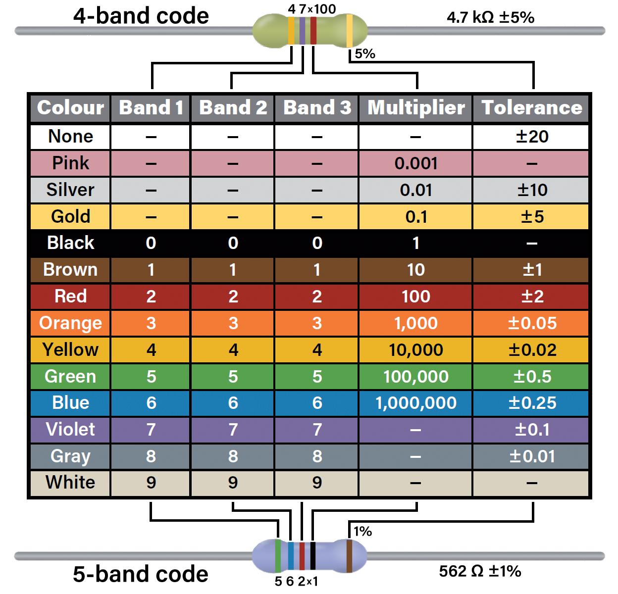
Figure 2.5 Resistor colour codes. Resistors with six bands exist too. The first five bands form a 5-band code, the 6th band indicates the temperature coefficient.
Example 1
A 4-band resistor has the colours red, red, orange, brown. Calculate its value and tolerance. From Figure 2.5 we have:
Red: 2
Red: 2
Orange: 1,000
Brown: 1%
The value is: 22 × 1,000 = 22,000 Ω or 22 kΩ with ±1% tolerance
This value can also be read from right to left, i.e. brown, orange, red, red, which corresponds to 1,300 Ω with ±2% tolerance. The reading direction is indicated by the tolerance band, which is either wider or placed apart from the other bands. In case of doubt, use an ohmmeter.
Example 2
A 4-band resistor has the colours yellow, violet, yellow, gold. Calculate its value and tolerance.
Chapter 2 • Passive Components ● 25
From Figure 2.5 we have:
Yellow: 4
Violet: 7
Yellow: 10,000
Gold: 5%
The value is: 47 × 10,000 = 470,000 Ω or 470 kΩ with ±5% tolerance
Example 3
A 5-band resistor has the colours: brown, black, black, brown, brown. Calculate its value and tolerance.
From Figure 2.5 we have:
Brown: 1
Black: 0
Black: 0
Brown: 10
Brown: 1%
The value is: 100 × 10 = 1,000 Ω or 1 kΩ with ±1% tolerance
This value can also be read from right to left, i.e. brown, brown, black, black, brown, which corresponds to 110 Ω with ±1% tolerance. The reading direction is indicated by the tolerance band, which is either wider or placed apart from the other bands. In case of doubt, use an ohmmeter.
Because of their small sizes, on surface-mount technology (SMT) resistors the value in ohms is printed on them as a 3- or 4-digit number. In a 3-digit representation, the first two digits are the numeric values, and the last digit is the number of zeroes. For example, 102 (Figure 2.6, left) represents ’10 00’ which is 1,000 Ω or 1 kΩ. Similarly, 103 represents ’10 000’ which is 10,000 Ω or 10 kΩ.
For low values, the letter ‘R’ is used as a decimal point. For example, 4R7 means 4.7 Ω (Figure 2.6, right).

Figure 2.6 1 kΩ and 4.7 Ω surface mount resistors.
For very small-sized resistors the EIA96 system is used, which involves a lookup table where a 3-digit value is used.
Practical Electronics Crash Course ● 26
Electronics Crash Course ● 270 Index 555 timer 101 74595 shift register 170 A AC 14 AD590 202 AND gate 155 Acceleration sensors 205 Active buzzer 49 Air capacitor 38 Air core inductors 42 Amplifier gain 20 Arduino UNO 140 Astable multivibrator 114 Atom 13 Atomic number 13 Auto transformer 60 Axial lead inductor 44 B Band-pass filter 193 Bandwidth 85 Bicolour LED 71 Bipolar transistor 85 Bistable 114 Breadboard 33 Buzzer 49 C Capacitor value marking 39 Capacitors 20 Carbon composition resistors 23 Carbon film resistors 23 Ceramic capacitor 38 Chip inductor 43 Choke 42 Circuit simulation 35 Colpitts oscillator 110 Common base configuration 85 Common collector configuration 85 Common emitter amplifier 86 Common emitter configuration 85 Comparator 150 Conductors 14 Continuity tester 126 Counters 157 Critically damped response 51 Current limiting 20 Current measurement 20 Current sensing transformer 60 D D flip-flop 165 DC 14 DPDT switch 103 DPST switch 102 DS18B20 202 Darkness detector 130 Datasheet 228 Depletion mode 94 Difference amplifier 143 Differentiator amplifier 150 Diode AND gate 164 Diode OR gate 163 Diode circuits 71 Diode logic 163 Distance sensors 206 E E12 series 21 E24 series 21 EMC 257 EMI 257 ESP32-DevKitC 222 Electrical characteristics 261 Electricity 13 Electrolytic capacitors 38 Electromagnets 55 Electromechanical relay 61 Electrons 13 Electronic buzzers 107 Electronic norms and regulations 257 Enhancement mode 94 F FPGA 172 Ferrite core inductors 42 Film capacitor 38
Practical
Index ● 271 Filters 20 Fixed-value resistors 21 Flip-flop 114 Float switch 101 Force sensor 197 Frequency 16 Full-wave rectifier 80 Function generator 210 H Half-wave rectifier 78 Hartley oscillator 112 High-pass filter 192 I IC families 140 Impedance 42 Inductor markings 43 Inductor values 43 Inductors 20 Insulator 23 Integrator 149 Inverting amplifier 144 Iron core inductors 42 Isolation transformer 60 J JK flip-flop 165 L LED 20 LED circuit 71 LM2576 207 LM2577 207 LM35D 201 LM386 183 LM75 202 Lamp/switch circuits 20 Light dependent resistor 130 Light-emitting diode 68 Limit switch 101 Logic gate 157 Loudspeaker 57 Low-pass filter 189 M MOSFET switch 96 Mechanical switch 56 Metal film resistors 23 Metal oxide resistors 23 Metal strip resistors 23 Metronome 132 Mica capacitor 38 Monostable multivibrator 114 Mosquito repeller 129 Multimeter 33 Multivibrator 114 Mutual inductance 46 N NAND gate 156 NE555 119 NOR gate 156 NOT gate 155 Neutron 13 Noninverting amplifier 146 Nucleus 13 O OR gate 155 Operational amplifier 143 Optocoupler 108 Oscilloscope 79 Overdamped response 51 P PCB design 257 Passive buzzer 108 Period 16 Phase-shift oscillator 113 Photodiode 67 Potential divider 199 Power rating 24 Proton 13 Push-button switch 49 R RC network 46 RC transient response 49 RCL transient response 51 RGB LED 69
Practical Electronics Crash Course ● 272 RMS 175 RTD 198 Raspberry Pi 222 Raspberry Pi Pico 222 Rectifier diode 66 Reed switch 56 Relay 61 Resistance measurement 215 Resistor colour code 24 Resistor networks 22 Resistor values 21 Resonance 176 Rotary switch 105 S SPDT switch 102 SPST switch 102 Schottky diode 66 Semiconductor 62 Semiconductor diode 67 Sensor 181 Shift register 158 Signal diode 65 Sine wave oscillator 109 Soil moisture sensor 205 Soldering iron 219 Solid-state relay 63 Sound sensor 204 Square wave oscillator 187 Summing amplifier 147 Switching circuits 66 T TDA2030 185 Tantalum capacitor 39 Temperature coefficient 24 Temperature sensor 196 Thermistor 32 Thermocouple 198 Toroidal inductors 42 Transformer 58 Transistor switch 90 Tunnel diode 66 U Underdamped response 51 V Varactor diode 67 Variable resistor 22 Varistor 32 Voltage divider 30 Voltage follower 147 Voltage gain 85 Voltage measurement 34 W Wire-wound resistors 23 X XNOR gate 157 XOR gate 157 Z Zener diode 67 Zener diode regulator 75
Practical Electronics Crash Course
Learning circuit design the fun way
Welcome to the world of electronics!
Getting started in electronics is not as di icult as you may think. Using this book, you will explore and learn the most important electrical and electronics engineering concepts in a fun way by doing various experiments and by simulating circuits. It will teach you electronics practically without getting into complex technical jargon and long calculations. As a result, you will be creating your own projects soon.
No prior knowledge of electronics is required, only some basic algebra is used in a few simple calculations. Many tested and working projects and simulations are presented to familiarise yourself with the construction of electronic circuits. Circuit simulation is introduced at an early stage to enable you to experiment with circuits easily without breaking anything.
You will learn:
> The concepts of voltage, current, and power
> AC and DC
> Basic lamp circuits with switches
> Passive components: resistors, capacitors & inductors
> RC & RCL circuits
> Electromagnetism
> Loudspeakers, relays, buzzers, and transformers
> Active components: diodes & LEDs, bipolar transistors & MOSFETs
> Transistor-based switching circuits
> Optocoupler circuits
> Astable & monostable multivibrators
> Using the 555 timer IC
> The operational amplifier
> Digital logic
> Advanced examples: amplifiers, oscillators, filters, and sensors
> Test and measurement tools
> Microcontrollers: Arduino UNO, ESP32, Raspberry Pi Pico, and Raspberry Pi
> Reading datasheets and best practices for selecting components
> EMC & EMI and norms & regulations

Prof Dr Dogan Ibrahim has BSc degree in electronic engineering, an MSc degree in automatic control engineering, and a PhD degree in digital signal processing. Dogan has worked in many industrial organizations before he returned to academic life. Prof Ibrahim is the author of over 70 technical books and published over 200 technical articles on microcontrollers, microprocessors, and related fields. He is a Chartered electrical engineer and a Fellow of the Institution of the Engineering Technology. He has been an amateur radio operator for several decades and also holds an Arduino certification.

Ahmet Ibrahim holds BSc (Hons) and MSc degrees in the fields of computing, software and networking. Ahmet has held positions in many industries involved in enterprise computing. He enjoys advising, designing and implementing complex cloud and on-premises computer systems. Ahmet is an experienced electronics engineer and an amateur radio operator.
International Media
Elektor
www.elektor.com
booksbooks