
www.augiworld.com US $8.00 The Official Publication of the AUGI Design Community April 2023 Diamond Sponsors SH Formas’ Ultimate Solution is BricsCAD | Collaboration Through Model Federation AUGIWORLD
in
issue: Collaboration
Also
this
Tools and Techniques


augiworld.com April 2023 | AUGIWORLD Magazine 3 CONTENTS 16 24 30 April 2023 AUGIWORLD FEATURES 6 BricsCAD SH Formas’ Ultimate Solution is BricsCAD® 10 BIM BIM Collaborate Pro: Collaboration for Civil 3D 16 Trimble Transforming Design and Construction with Trimble 3D Warehouse AR Viewer Technology 20 Dynamo C3D SSM ADynamo For Civil 3D – A Production Use Case 24 BIM | CIM Collaboration Through Model Federation 30 Solidworks Mechanisms & Mentorship: Symmetric Over-Center Clamping Mechanism 36 AutoCAD Civil 3D Labels: Express Yourself with Expressions! COLUMNS 4 Letter from the President 22 Inside Track 28 Tech Manager
From the Editor-in-Chief
This month’s focus is on collaboration. Collaboration is something we do daily in our jobs and personal lives. Whether it be collaborating over a project deadline or having a conversation with your spouse about how much money to put in savings for vacation.
There are several definitions for collaboration, but all of them state that it takes two or more people with different skill sets to produce something. The term collaboration can also translate to teamwork.
Some of you may know that I build custom choppers/ bobbers as a hobby. It is imperative that I collaborate with someone on my builds because a lot of the time, I don’t know the answer. Reviewing posts and YouTube videos sometimes doesn’t do the trick. So, I need to collaborate with other builders to get their input on what I should and should not do in the case of the question at hand. Sometimes this produces a different route all together. For example, if I’m putting on 14” ape hangers, what length of cable do I need for the clutch and brake? Ok, then how do you measure for that? Collaborating with a gentleman on a post, he suggested using a piece of string to run along the handlebars, down to the carburetor, then measure that length of string with a measuring tape. Boom! Would you believe the clutch cable is 70”? Yep, if I didn’t measure this right, I would have ordered something like 24-30”.
There are several benefits to collaborating with a team. Some of the benefits include increased productivity, enhancement of social skills, common goals, diversity, and even learning. Simple communication between individuals can produce a number of ideas and solutions and will allow you to order the correct length clutch cable!
Sincerely,
Editor-in-Chief
AUGIWORLD
www.augi.com
Editors
Editor-in-Chief
Todd Rogers - todd.rogers@augi.com
Copy Editor
Isabella Andresen - isabella.andresen@augi.com
Layout Editor
Tim Varnau - tim.varnau@augi.com
Content Managers
3ds Max - Brian Chapman
AutoCAD
AutoCAD Civil 3D - Shawn Herring
Bentley
BIM/CIM - Stephen Walz
BricsCAD - Craig Swearingen
Dassault Systèmes - Rafael Testai
Electrical - Mark Behrens
Manufacturing - Kristina Youngblut
Tech Manager - Mark Kiker
Inside Track - Shaun Bryant
Advertising / Reprint Sales
Kevin Merritt - salesmanager@augi.com

AUGI Executive Team
President
KaDe King
Vice-President
Frank Mayfield Treasurer
Todd Rogers
AUGI Board of Directors
Eric DeLeon
KaDe King
Chris Lindner
Frank Mayfield
Todd Rogers
Scott Wilcox
Publication Information
AUGIWORLD magazine is a benefit of specific AUGI membership plans. Direct magazine subscriptions are not available. Please visit www.augi.com/account/register to join or upgrade your membership to receive AUGIWORLD magazine in print. To manage your AUGI membership and address, please visit www.augi. com/account. For all other magazine inquires please contact augiworld@augi.com
Published by:
AUGIWORLD is published by AUGI, Inc. AUGI makes no warranty for the use of its products and assumes no responsibility for any errors which may appear in this publication nor does it make a commitment to update the information contained herein.
AUGIWORLD is Copyright ©2023 AUGI. No information in this magazine may be reproduced without expressed written permission from AUGI.
All registered trademarks and trademarks included in this magazine are held by their respective companies. Every attempt was made to include all trademarks and registered trademarks where indicated by their companies.
AUGIWORLD (San Francisco, Calif.)
ISSN 2163-7547
AUGIWORLD Magazine | April 2023 augi.com 4


A Global Community for AEC Professionals to Learn, Grow and Exchange Knowledge. Become a member: www.dbei.org/membership
SH Formas’ Ultimate Solution is BricsCAD®
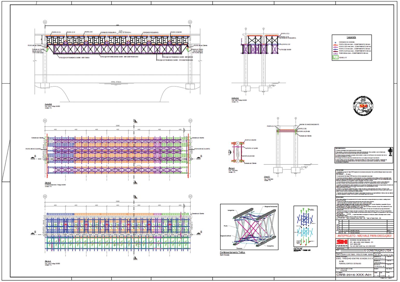
SHFormas is an industry leader in formworks, scaffolding, and shoring for sale and rental in Brazil, including the widest distribution in Brazil and the largest presence across Latin America. The sales and technical teams at SH Formas work with highly customized layout and assembly workflows, supporting services on thousands of projects across Brazil, Paraguay, and Colombia.
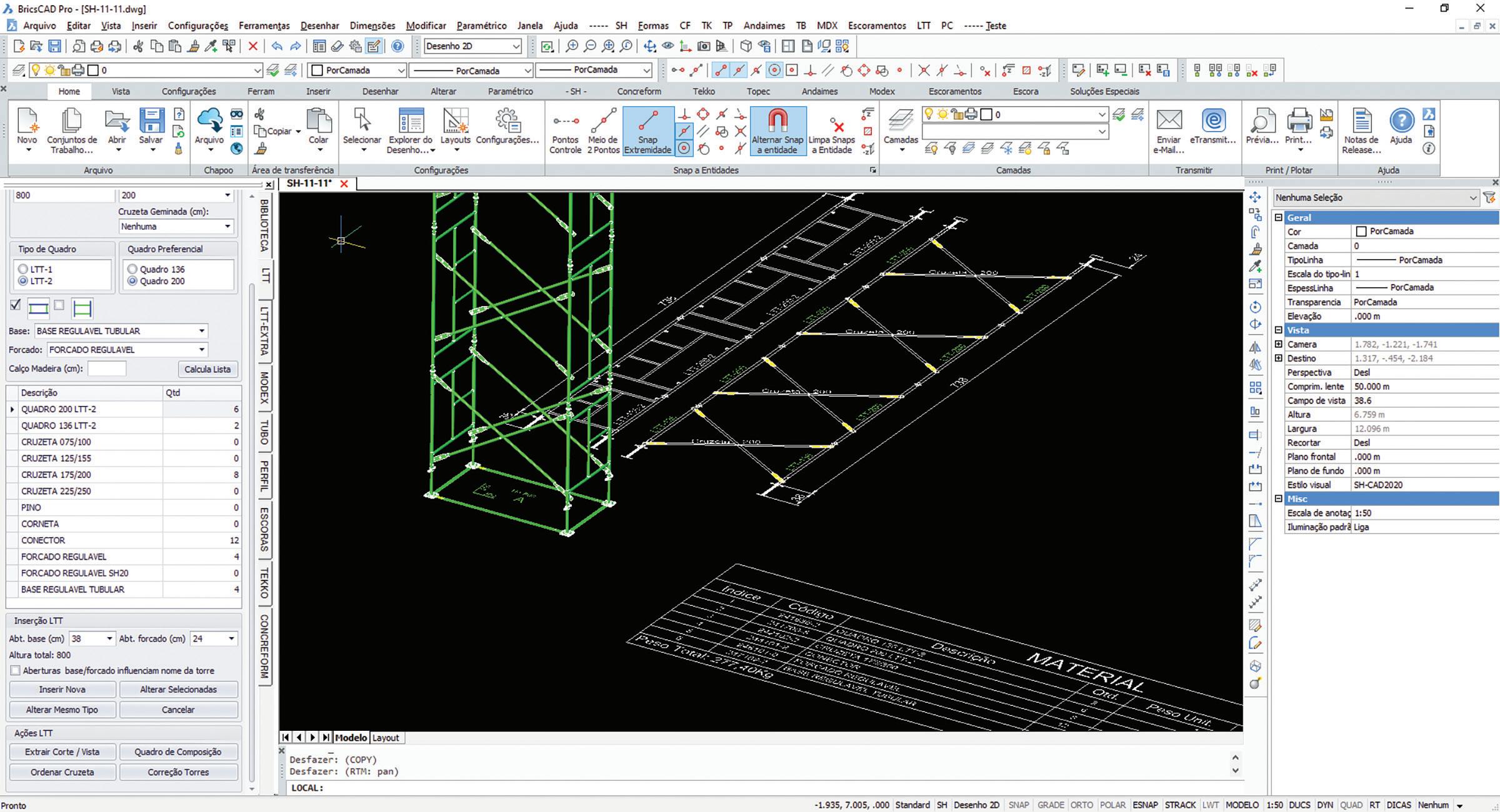
SH Formas’ challenge was to upgrade their CAD to a robust and powerful solution, running in-house customizations and generating deliverables more productively and less expensively than their legacy CAD (See Fig. 1).
BricsCAD stood out among the leading competitors because, year after year, Bricsys’ product teams added capability and improved functionality.

Michael Rock, Technical Director at SH Formas, told how BricsCAD
improved their designers’ workflows immediately. “When we switched to BricsCAD, many problems were solved by having a reliable platform. Of the many CAD solutions, BricsCAD was always improving.”
AUGIWORLD Magazine | April 2023 augi.com 6
BricsCAD
by: Craig Swearingen
1
Figure
SEAMLESS CUSTOMIZATION AND OPEN API
Over the years, SH Formas has built an extensive library of parametric 2D and 3D parts and many other programming customizations. SH Formas’ customizations run seamlessly on BricsCAD’s open API, and as Michael detailed, “We rely on our customizations about 90% of the time we spend in BricsCAD. If I insert any block, I do not use the insert command, I use our customization.”
FLEXIBLE, PERPETUAL LICENSING
When Brazil suffered an economic slowdown in the mid-part of the last decade, impacting SH Formas’ markets, the company also appreciated the value of Bricsys’ perpetual licensing option.
Michael recalled, “There was an economic crisis between 2015 and 2017, which was a difficult time. We were grateful to have our [perpetual] CAD solution paid in advance, passing through this phase.”
Many perpetual license holders subscribe to BricsCAD Maintenance to keep their licenses current. This cost-effective yearly subscription provides updates on the latest versions, plus many benefits like priority support with expert assistance.
DELIVERABLES FROM 2D/3D INTEROPERABILITY
SH Formas’ team assemble designs, which are complex and often repetitive, from a pre-defined list of parametric parts developed in-house. Their team feels it’s more productive when working directly with 2D projections of these parts.
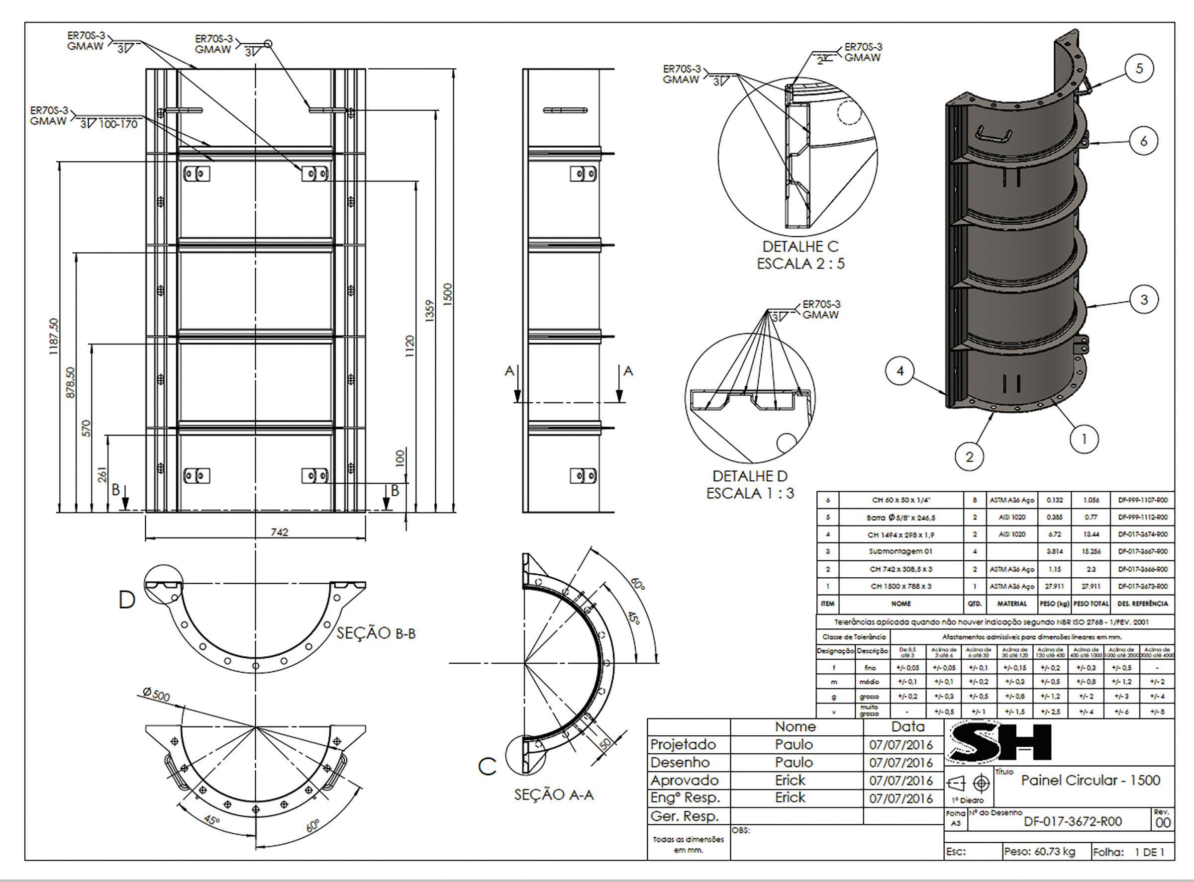
With BricsCAD’s 2D/3D interoperability, SH Formas can also get the final drawing out quickly and generate a list of materials. As Michael Rock described, “Sometimes it’s easier to think about a solution in 2D than to make a 3D model,” (See Fig. 2).
DESIGN FLEXIBILITY: A SINGLE, INTEGRATED CAD AND BIM SOLUTION
The significant gain for SH Formas is the ease of working on the single, integrated 2D/3D workspace within BricsCAD. SH Formas has both the BricsCAD Pro and Ultimate licenses, and this additional BricsCAD BIM capability, included in Ultimate, allows their teams to work in 2D, 3D, and with BIM models when needed.
As Michael stated, “If the customer opens their BIM model, we can place our equipment inside theirs. We can use our model and easily add BIM information, so I can supply a BIM model of our scaffolding, shoring, or formwork solutions.”
augiworld.com April 2023 | AUGIWORLD Magazine 7
BricsCAD
Figure 2
THE FUTURE WITH BRICSCAD’S POWERFUL MODELING ENGINE
Most of the SH Formas’ processes are currently in 2D. However, SH Formas wants to utilize more 3D in their workflows gradually. In doing so, they will take advantage of running on BricsCAD Ultimate›s DWG-based 2D/3D and BIM package.
The company has been experimenting with BricsCAD® Ultimate to do more 3D modeling in the future, with positive results from the early trials in their workflows. Michael confirmed, “We like the approach of BricsCAD in 3D modeling. Just grab a surface and split it or modify it.”
Further explaining, “What we are planning is taking the main part of the business to the next level with more 3D detailing and assembly drawings.”
BricsCAD’s design solutions have been central to SH Formas’ service delivery, both companies innovating in their markets to drive productivity, capability, and exceptional value. (See Fig. 3)
MORE ABOUT BRICSCAD®

Explore all the BricsCAD editions and features by downloading the free, 30-day trial of BricsCAD Ultimate. The latest BricsCAD V23 improves the tools and features users love, as well as new functionality and UI that supercharge productivity.
Mr. Craig Swearingen is a Global Implementation Specialist and Consultant at Bricsys. Currently, Craig provides migration and implementation guidance, management strategies, and technical assistance to companies which need an alternative, compatible CAD solution. Craig spent 19 years in the civil engineering world as a technician, Civil 3D and CAD power user, becoming a support-intensive CAD/ IT manager in high-volume production environments. Craig is a longtime AUGI member (2009) and a Certified
AUGIWORLD Magazine | April 2023 augi.com 8 BricsCAD
Figure 3


AUGIWORLD Print AUGI HotNews Digital Visit www.AUGI.com/advertise Connect with AUGI Members Increase your revenue by advertising with AUGI and reaching its 400,000 Members. AUGI.com Website Thousands of visits per month Forum Advertising Active membership participation • Advertising Email Blasts • Targeted Mailings • Industry Leading Google Results Site US $8.00 The Official Publication of the AUGI Design Community Diamond Sponsors Implementing Best Strategies Automating Punch Lists with Bluebeam Revu Setting Up System Variables for Success in AutoCAD AUGIWORLD Also in this issue:
BIM Collaborate Pro: Collaboration for Civil 3D
Autodesk’s Construction Cloud platform connects project teams with a suite of products, from design to construction, all working from centralized project data. This unified platform centralizes data in Autodesk Docs, where Construction Cloud applications can utilize the data across the project lifespan. One product, Autodesk BIM Collaborate Pro, connects Revit, Civil 3D, and Plant 3D with seamless cloud collaboration. These tools are consistently improving and expanding, including some exciting advancements for collaborating in Civil 3D.
These advancements include a Sheet Set Manager designed for the cloud, a new and improved Desktop Connector, and up to 25% faster opening
times. These build on an existing feature set that allows you to seamlessly collaborate on a Civil 3D project in the cloud. In this article we will explore how to setup and use the Collaboration for Civil 3D tools in the Autodesk Construction Cloud.
CLEARING UP THE TITLES
When it comes to the Autodesk Construction Cloud, there are quite a few product names and titles, many of which sound the same. It can be quite confusing. Before we dive into the nuts and bolts, let’s clear up some of this naming.
First, Autodesk Construction Cloud is the name of the platform, a collection of products for different areas of the project lifecycle. These products

AUGIWORLD Magazine | April 2023 augi.com 10 BIM
by: Bryson Anderson
include, Docs, Collaborate, Collaborate Pro, Build, and Takeoff. Each product is a toolset, containing several sub tools or modules. The two products we will focus on, are Docs and BIM Collaborate Pro
The core of the Autodesk Construction Cloud (ACC) platform is the Document Management product, called Autodesk Docs or simply, Docs. This includes the Project Setup, Administration and Document Management tools.
The Account Admin web tool is where anything ACC gets started. This is where projects are created and configured, companies and members are added, analytics are reviewed, Etc. The Project Admin web tool is used to configure and administer an existing project, and the Project Home dashboard gives you quick insight into project status and information.
The Document Management module, Docs is the data repository, where all project files are stored, folder access is granted, file viewing, markup and issue creation occurs, etc. You can subscribe to Autodesk Docs by itself and take advantage of these modules, or by subscribing to any other ACC product, access to the Docs product is included with that subscription.

BIM Collaborate Pro extends the project data to Revit, Plant 3D, and Civil 3D for cloud collaboration and work-sharing. As mentioned earlier, a seat of Collaborate Pro grants that user access to all the tools of Autodesk Docs, as well as the collaboration tools. Collaborate Pro also includes the Model Coordination module for cloud clash detection and review.
There is also a package, BIM Collaborate that includes the Docs module, as well the Model Coordination module, but lacks the Collaboration tools included with Pro.
The Design Collaboration module, who’s name often gets confused with the Revit Cloud Worksharing tool or the entire BIM Collaborate Pro product, enables organization and control of each project team’s data and how other project teams can see and consume one another’s data. I wish Autodesk would have named this module differently as they used very similar wording in marketing and help material. Don’t be surprised if you see material from Autodesk or otherwise that use the term ‘Design Collaboration’ for more than just this module.
The collaboration module for Civil 3D, in the BIM Collaborate Pro product, and focus of this article is Collaboration for Civil 3D. Using the Desktop Connector, a desktop service that connects Windows File Explorer with your ACC data, extended project teams can collaborate on Civil 3D projects, with automated file locking, XREF and Data Shortcut support. See Figure 1.
As the Autodesk Construction Cloud platform has evolved, names have been changed, and in some cases, very similar names have been used for different tools and products, creating quite a bit of confusion. This hopefully clears up some of that confusion with Autodesk Construction Cloud, and its product and module naming.
GETTING SETUP
Before getting into the nuts and bolts of Collaboration for Civil 3D, there are a few things
augiworld.com April 2023 | AUGIWORLD Magazine 11 BIM
1
Figure
you need to do in preparation. The first step is to ensure your Autodesk User Account has a BIM Collaborate Pro license assigned to it. ACC products are single named user subscriptions. This means a subscription, or seat of the product needs to be assigned to your Autodesk User Account, so when you login, the system recognizes you are licensed to use the product. Licenses are assigned by your Autodesk Account Administrator via the Autodesk Account.
Before you can start uploading files, you need a place to put them, an ACC project, setup in Docs. If you are an ACC Account Admin, you can create a new project, or if you are joining an existing project, you will need to be invited by an admin of that project. This project could be in your company’s ACC Account, or another company’s ACC Account.
The ACC Account is the overall storage container for a company’s projects, and configurations. You will likely be invited to projects on multiple accounts. Projects in both Desktop Connector, and the ACC Web interfaces are listed under their associated account name as the parent folder. When someone invites you to a project on their Account, and you accept the invitation you receive via email, you will then see that account, and any project(s) from their account you are invited to in your project list.
A quick note on Autodesk BIM Collaborate Pro (ABC Pro) licensing. A seat of ABC Pro assigned to your Autodesk User account allows you to use the ABC
Pro tools on all Accounts/Projects you are invited to. This is a ‘bring your own license’ model, meaning you as a user are licenses to use the product, and that license follows you to any project you are invited to.
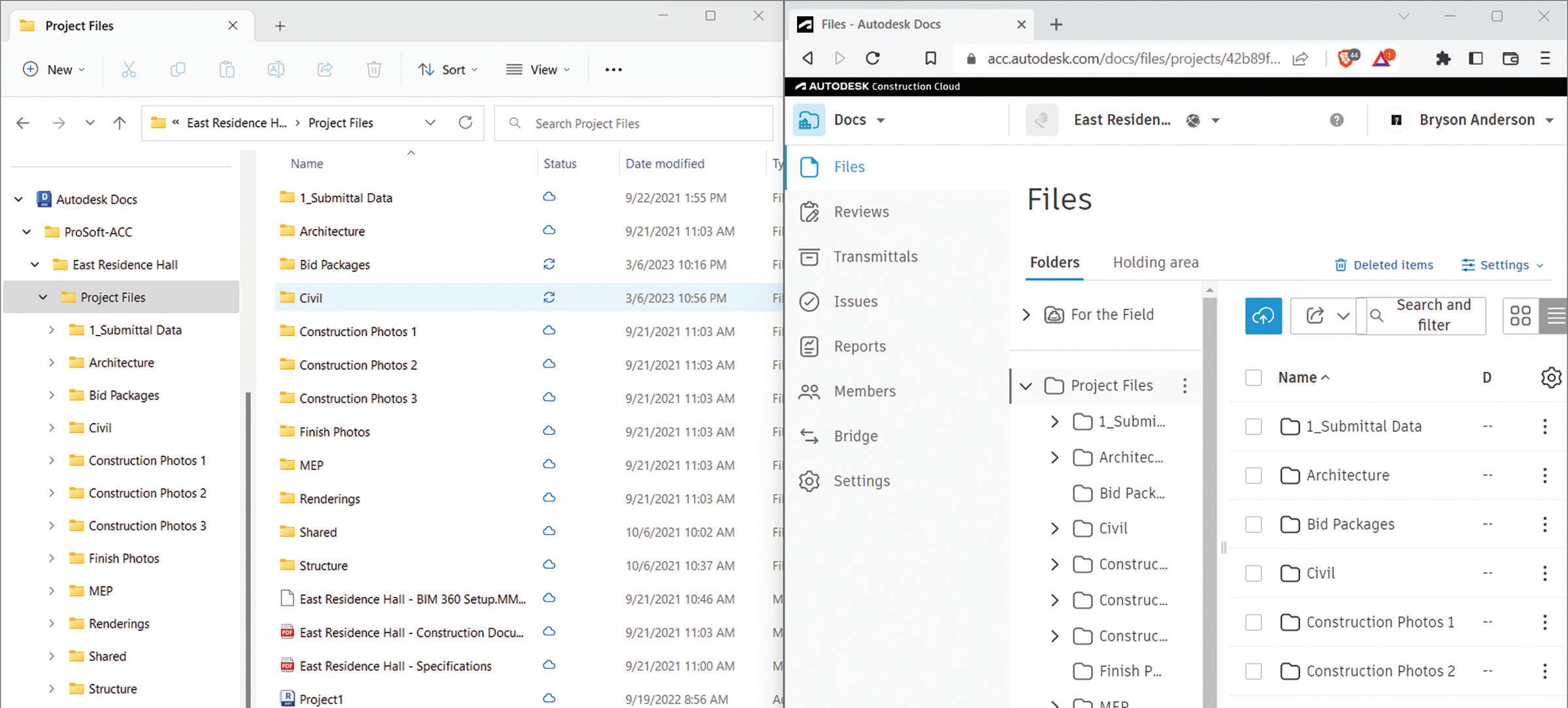
The last step is to install and sign into the Autodesk Desktop Connector. You can download the Desktop Connector from your Autodesk Account, on the All Products and Services tab. The installation is simple, run the .exe file that is downloaded, and click Install. Once the installation finishes, sign in with your Autodesk account. This will put an ‘Autodesk Docs’ location in ‘This PC’ in your Windows File Explorer. You will then be able to access any ACC accounts, and projects you are invited to via Windows File Explorer. See Figure 2.
The Desktop Connector functions in a ‘files on demand’ method. This means though you see the entire set of files/folders, they are not all stored on your local system. When you access a file, it is then downloaded to your system and cached locally until it has been unused for 15 days, after which it will be automatically removed from your local cache.
The latest version of the Desktop Connector, version 16, also called the Autodesk Docs Connector, has some exciting new features including right click commands from both Windows, and Docs Connector, upload and file reference tools and improved file locking.
AUGIWORLD Magazine | April 2023 augi.com 12 BIM
2
Figure
Now that you have Desktop Connector installed and connected, a license to BIM Collaborate Pro, and are a member of an ACC project you can get started with setting up and using Collaboration for Civil 3D.
CONFIGURATION AND ACCESS
The first step is to set up the project folder structure in the project. This can be done in the Docs web portal or using the Desktop Connector through file explorer. If you have a folder structure already created you want to copy to this project, use the Desktop Connector as there currently is not a folder upload in the web portal. In versions 15 and below of the Desktop Connector, there is no right click context menu in the Desktop Connecter for Copy/ Paste. Copy your project data in by dragging and dropping, or CTRL-V to paste. In version 16, you can use the Copy/Cut/ Paste command built into File Explorer.
Once you have pasted or dragged and dropped in your data, a ‘Transferring Files’ window will appear to let you know your files/folders are being uploaded. You can also monitor the upload status via the Pending Actions dialog. In the System Tray of Windows, you will see the gray icon with a white ‘D’ Symbol of the Desktop Connector. Right click on the icon and select ‘Pending Actions’ to open the dialog box in versions 15 and older. In version 16, pending actions appear on the pop-up window that appears when clicking on the Desktop Connector icon in the system tray.
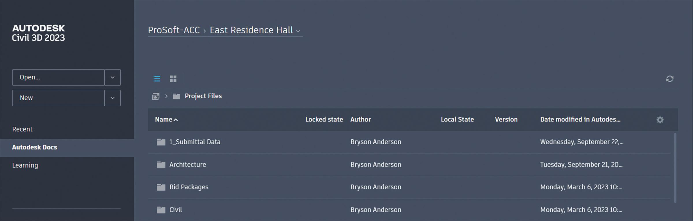
Now that you have your data uploaded, it’s time to open Civil 3D. Currently, only Civil 3D 2020.2 and later is supported. If you do not have the 2020.2 update installed, you need to install the update before continuing. The start screen for Civil 3D on
a supported version will have a ‘Autodesk Docs’ location where you can browse the Accounts/ Projects you have access to. The dropdown at the top of the screen allows you to switch which projects folders you are browsing. Clicking ‘Change Account’ will show you all Accounts you have access to, selecting an Account will then list the available projects.
On the metadata ribbon, to the far right is a gear icon that lets you select what metadata columns you see about the files. I like to turn on at least Locked State, Local State, and Locked By fields. Click on the file you want to open, or right click to select between Open and Open Read-Only. See Figure 3.
augiworld.com April 2023 | AUGIWORLD Magazine 13 BIM
3
Figure
IF YOU HAVE A FOLDER STRUCTURE ALREADY CREATED YOU WANT TO COPY TO THIS PROJECT, USE THE DESKTOP CONNECTOR AS THERE CURRENTLY IS NOT A FOLDER UPLOAD IN THE WEB PORTAL.
As the file opens, the file is automatically locked so no one else can modify the file while you have it locked. (Unless of course you selected Read-Only, or it was already locked, and it forced Open Read-Only)
To save your changes, simply click ‘Save’ in Civil 3D and your changes will be saved locally, and the Desktop Connector will begin uploading the modified file.
DATA SHORTCUTS AND XREFS

Next you need to set your Data Shortcuts working folder. Data shortcuts in Collaboration for Civil 3D use the same Data Shortcuts in Toolspace, on the Prospector tab as when you’re working locally, but you will now select an Autodesk Docs location via the Desktop Connector as the working folder. If you do not yet have a Data Shortcuts Project folder in your folder structure, create one. Then set the working folder to that location. Right click on Data Shortcuts, and select Set Working Folder, then browse to the Docs location for your shortcuts. Once selected, you will see a Blue cloud icon, as well as an ACC Docs:\... location set. See Figure 4.
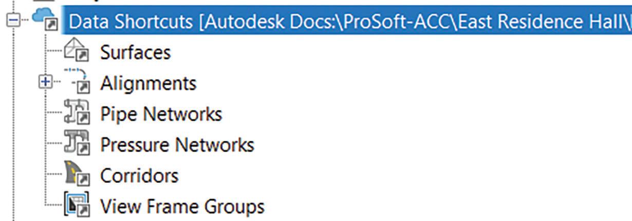
You can then create and reference Data Shortcuts the same way you are used to working locally.
Civil 3D X-References are also supported. When dragging and dropping / pasting files through the Desktop Connector, XREFS are automatically checked, uploaded to Docs and paths updated. Even if you only copied in the host drawing, the XREF check will see that drawing has a reference, automatically go get that reference file if it can be resolved, and upload it, updating the path to a Docs path. The referenced file will be copied to the project location, replicating the directory structure where it was found. If it is not able to resolve the reference, you will get an error message saying ‘Failure Gathering References’ and the missing XREFS will be ignored, and the host drawing uploaded with a broken reference.
To create a new reference, you follow the same procedure you normally do, but select the file to be referenced from the Desktop Connector folder structure. If you look at the absolute path for a reference, you will notice its pathing to your C:\ Users\UserName… Folder. But do not worry, the Desktop Connector makes the translation in the background to the cloud. Even though it shows a local path, when another user opens it, it shows their local location of the desktop connecter, the translation from local folder to cloud is being made in the background.
SHEET SET MANAGER
Previously, the weak point in the Collaboration for Civil 3D workflow was the lack of support for Sheet Set Manager. That has now changed, Autodesk has developed a sheet set manager, based on the legacy Sheet Set Manger tool designed specifically for Autodesk Docs workflows. This new tool, Sheet Set Manager for Web is a Lightweight version of the legacy Sheet Set Manager, providing these core functionalities.
• Create cloud sheet sets.
AUGIWORLD Magazine | April 2023 augi.com 14 BIM
Figure 4
• Manage support files.
• Create, remove, or move sheets and subsets.
• Define sheet set and sheet properties.
• Automatically number new sheets
• Rename or renumber sheets.
• Import sheets.
• Publish sheet sets to PDF.
• Transmit sheet sets.
Opening an existing .DST file from Autodesk Docs will automatically open the sheet set in the new Sheet Set Manager for Web tool. Browse for the .DST file through the Desktop Connector in File Explorer and double click to open it. Opening through the legacy SSM tool in Civil 3D will open in the legacy tool. Once open, you will see tools for the core functionalities listed above. You can also see all users who are collaborating on the sheet set by clicking the members icon in the top right corner. See Figure 5.
You can create a new sheet with the ‘Add Sheet Set’ button in the top left corner of the Sheet Set Manager for Web tool, or in the legacy SSM tool by clicking Add Sheet Set and selecting ‘Cloud Example Sheet Set’ and filling out the sheet set details. You can also save an existing sheet set to Autodesk Docs and open it through File Explorer.
This new tool has very familiar toolset naming, look and feel as the legacy sheet set tool. It will be an easy transition for users to seamlessly start using this new tool with very little learning curve. Utilizing the new Sheet Set Manager for web, users can now utilize sheet set workflows on Civil 3d projects in Autodesk Docs.

CONCLUSION
The Collaboration for Civil 3D module of BIM Collaborate Pro is constantly advancing, adding new features and improved speed. Utilizing BIM Collaborate Pro, you can improve your Civil 3D workflow extending collaboration, anywhere, anytime.
Bryson has worked in the IT industry since 2008. During this time, he has been involved in many aspects of IT including, Systems Administration, Networking, Telecom, Hardware, and IT consulting. He has supported large and small companies in a variety of industries including healthcare, software development, engineering, and architecture; plan, implement, upgrade and maintain their IT infrastructure. At ProSoft, Bryson admins all aspects of the internal IT infrastructure, and oversees ProSoft’s managed IT services, and custom workstation and server division. With his knowledge and experience in IT, he consults with companies worldwide on the planning, implementation, and training of Autodesk data management and collaboration software. As well as assisting customers with the licensing, installation, and deployment of Autodesk products.

augiworld.com April 2023 | AUGIWORLD Magazine 15 BIM
Figure 5
Transforming Design and Construction with Trimble 3D Warehouse AR Viewer Technology

Istill recall my first experience with augmented reality (AR) technology. It was a new feature on my mobile phone’s camera app, which allowed me to add fun characters and scenes to my surroundings. Within seconds, I found myself transported to the Mesozoic Era, surrounded by prehistoric creatures and lush foliage.
As augmented reality (AR) technology has advanced, its uses have expanded to a wide range of applications. One prime example is the popular game Pokemon Go, which transformed the use of AR by involving users in immersive and interactive experiences. By encouraging people to explore their surroundings and connect with others, AR technology has opened up new and exciting possibilities for engagement and play.

AUGIWORLD Magazine | April 2023 augi.com 16 Augmented Reality by: Kristina Youngblut
Figure 1: [Photo credit: www.facebook.com/PokemonGO ]
INTRODUCING TRIMBLE
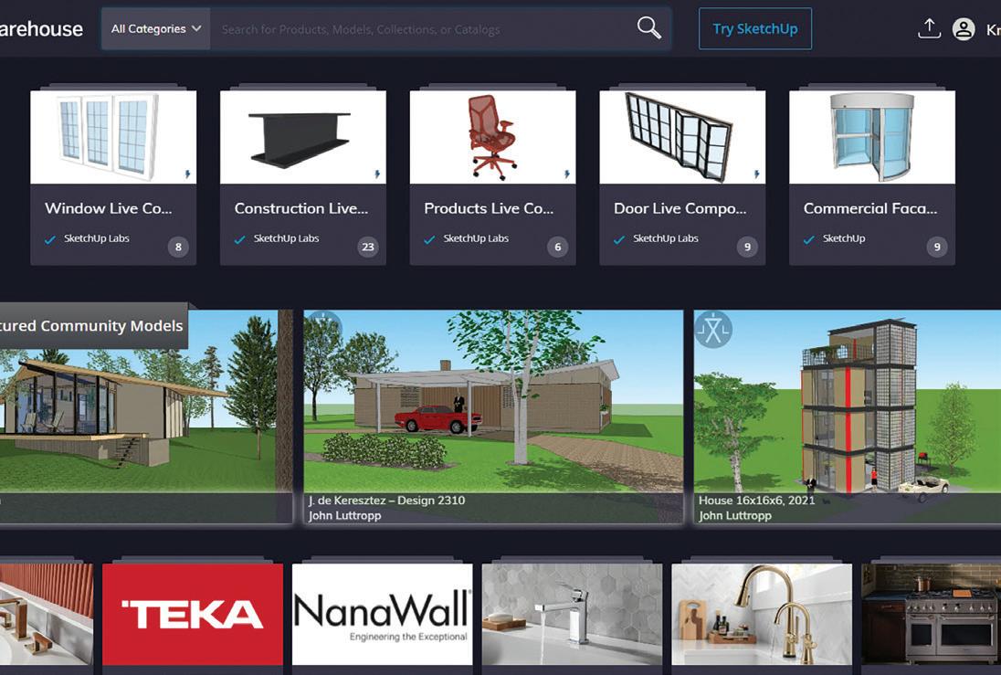
A lot has happened and transformed within the world of AR since the technology first became available, and in March of 2022, Trimble released the AR Viewer on the 3D Warehouse site. With the ability to upload your SketchUp content to an online platform you can visualize your models anywhere and anytime. With the addition of the AR Viewer solution, Trimble’s 3D Warehouse has become a one-stop-shop for design visualization and collaboration. This advanced AR viewer allows users to conceptualize their 3D designs and models in the real world. This technology has the potential to transform the construction and design industries, from boosting collaboration to improving decisions, making the process more efficient, cost-effective, and enjoyable for everyone involved.

CONSTRUCTION AND DESIGN
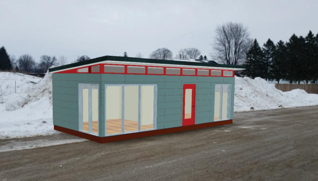
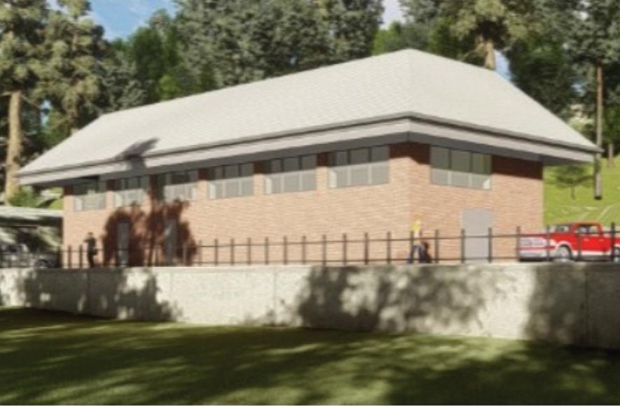
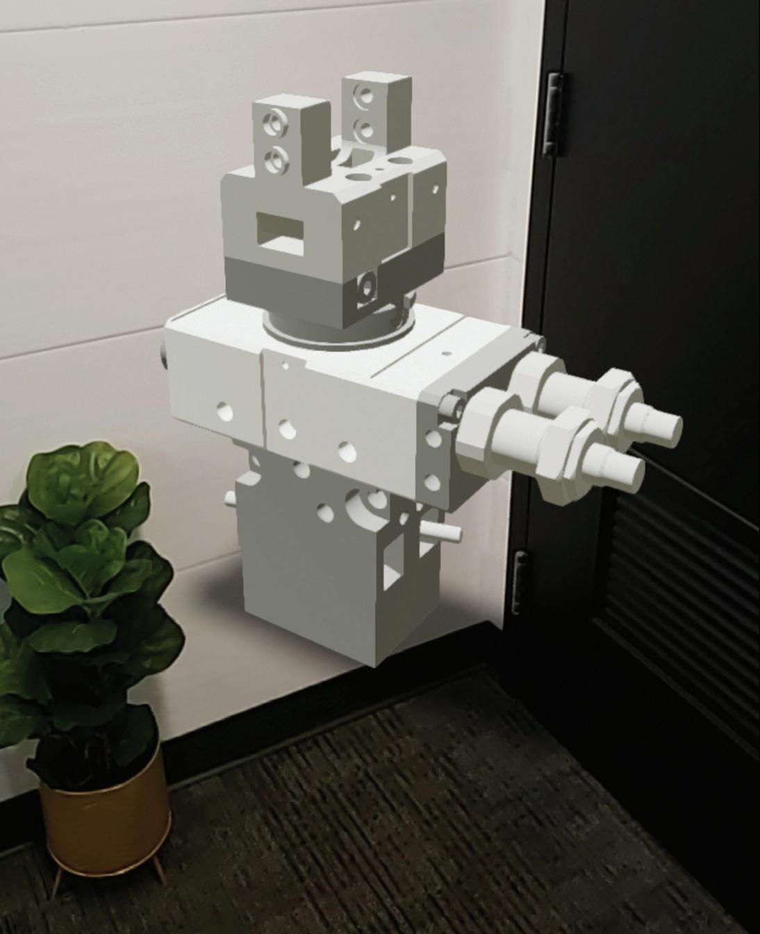
Envision strolling through a construction site, where the completed building appears before you with a simple tap on your screen in stunning 3D detail—allowing you to not only see the completed building but being able to manipulate its scale and orientation to get a better sense of how it will look and function in its environment (figure 2).
Trimbles AR Viewer isn’t just limited to construction sites. It’s also a game-changer for designers and manufacturers, allowing them to create virtual prototypes of their products in real-world settings. This technology allows manufacturers to test and refine their designs, ensuring the final product meets their desired specifications. The AR Viewer can also aid in product demonstrations, giving customers a realistic sense of how a product will look and function in their intended environment (figure 3).
WHAT IS AR (AUGMENTED REALITY)
AR stands for “augmented reality,” which is a technology that enhances the user’s perception of reality by overlaying digital information or images onto the real world in real-time. It allows users to interact with virtual objects in a real-world environment and creates an immersive experience that blends the physical and digital worlds. AR can be experienced through a range of devices, such as smartphones, tablets, headsets, or glasses.
augiworld.com April 2023 | AUGIWORLD Magazine 17
Augmented Reality
Figure 2
Figure 3
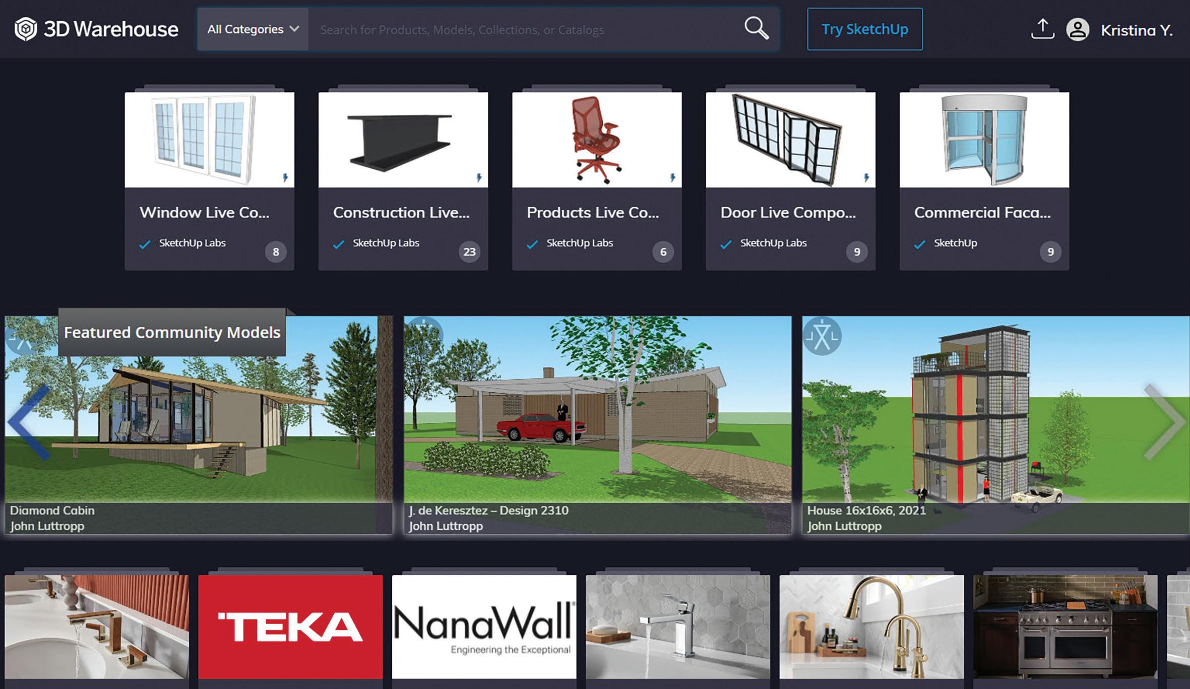
HOW DO I USE THIS SERVICE?
Simple, if you don’t already have one, head over to 3dwarehouse.sketchup.com and sign up for a FREE account. This is a requirement to view content on this service (figure 4).
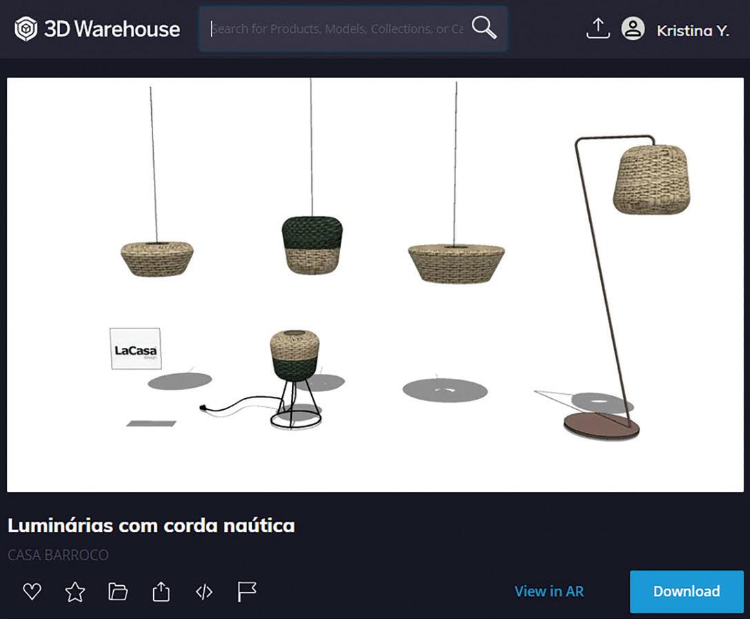
Once logged in, you can easily upload any SketchUp model, and after it has been re-rendered, the model will generate a link to View in AR. Additionally, the platform boasts a massive user-supported content
library with virtually limitless options for your AR projects (figure 5).
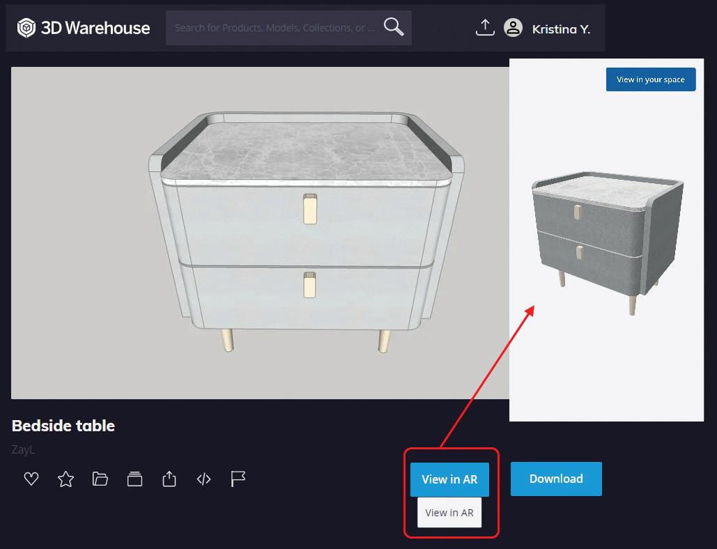
HOW DO I VIEW THE MODELS IN AR?
There are multiple ways to utilize the AR Viewer depending on the device you use to access it. The simplest and most convenient way is through your smartphone. After uploading your model, the AR Viewer generates a View in AR link that directs you to a 3D Viewer page. From there, all you need to do is select “View in your space” and position
AUGIWORLD Magazine | April 2023 augi.com 18 Augmented Reality
Figure 4
Figure 5
Figure 6
the object in your room. The process takes mere seconds, making it quick and easy to see how your creation fits in your space (figure 6).
For tablets, desktops, Hololens, and other devices, you will need to download the appropriate AR Viewer app and access the content through a QR code generated from the View in AR link (figure 7).

WHAT CAN THIS DO FOR MY COMPANY?
With Trimble’s AR Viewer technology, you can showcase your products, buildings, or other creations to potential clients or decision makers, giving them a visual experience that was once impossible.
Worried about installation problems or clearance issues? With AR, you can provide solutions on the spot and save time waiting for clarification. By using AR, you can reduce downtime and confusion, making problem-solving easier and more efficient (figure 8).
When it comes to presentations, the AR Viewer is a game-changer. Rather than simply presenting slides or images, you can put the product in the hands of your attendees and allow them to explore and interact with it. This creates a more engaging and memorable experience that can leave a lasting impression.
Overall, Trimble’s 3D Warehouse AR Viewer is transforming the way designers, architects, engineers, and construction professionals visualize their designs. It’s a powerful tool that can make problem-solving easier and more efficient while providing an immersive experience for potential clients and decision-makers.
CONCLUSION
The AR Viewer by Trimble is an exceptional and easily accessible tool that has the potential to revolutionize the way you present and showcase your products or designs. Whether you want to provide a detailed demonstration of installation or give potential clients a visual tour of your creations, the AR Viewer is the perfect solution. Best of all, it’s free to use! So, take some time to explore its capabilities and see for yourself how it can enhance your presentations and demonstrations. You won’t be disappointed!
Kristina Youngblut is a CAD solutions and technologies expert with over 20 years of experience in the Architecture, Engineering, and Construction (AEC) community. Her main focus is on providing innovative solutions and technologies for professionals in the manufactured products sector. She is also an active Autodesk author, sharing tips and solutions with various Autodesk software.

augiworld.com April 2023 | AUGIWORLD Magazine 19 Augmented Reality
Figure 7
Figure 8
Dynamo For Civil 3D – A Production Use Case

As you all may know, Autodesk Dynamo is a plugin used for “visual coding” which, in a nutshell, is lots of boxes and strings that lead to a form of production automation. This was first introduced for the architectural/structural space while very little information is out there for Civil 3D use cases. In this article I will be demonstrate what is the most recent way I have been able to levarage this technology at Walter P Moore.
As a Civil Engineering Drafter, I have encountered a number of issues in my short career ranging from file corruption due to data being in multiple servers to something as simple as renaming/renumbering sheets. Soon after I found Dynamo, I began brainstorming what would be the perfect way to leverage a couple lines of code and thought “why not let code rename/renumber for me”, so, then began my quest for finding answers but unfortunately nothing on Civil 3D as most information points towards Revit.
While I am fairly new to this space and also lack a network that knows how to code, my last resources was to seek counsel in Fiverr which is an outsourcing website that has numerous of reputable coders overseas. After building out my requirements I sent it out and got the Dynamo design built although lacking some logic to make it function which is where I began tweaking it and made it work.
I came out with two iterations as shown below:
SSM-V1: Renames/Renumbers
SSM-V2: Renames/Renumbers & Repaths
Now you may as why would I like to repath, well, during the time we were about to do a redesign of the same project, so a copy of the existing files was completely necessary. But as you all may know that only gets you so far also, we had to renumber all of our sheets (80-100 total give or take). I had been estimating this would probably take quite a bit so by that time I already had my V-2 available and it
was time to put it to the test…Which I succeeded cutting down at minimum 60-80% of what it would have taken renaming all of them which just took approximately 10 seconds.
In conclusion there are a lot of great tools to use, but the path is not always there which is where we need to come together as a community to pave the way and continue innovating. I would like to thank my peers at Walter P Moore as we always stride to make tomorrow a better place.
Marco Oregon is a highly skilled and experienced Civil Engineering Technician with a passion for optimizing the workplace through the use of cutting-edge technology. With a focus on utilizing tools offered by Civil 3D and third-party providers, Marco is dedicated to streamlining workflows, improving efficiency, and driving results for his clients and colleagues. Throughout his career, Marco has demonstrated a deep understanding of civil engineering principles, as well as an ability to translate complex technical information into actionable insights for both technical and non-technical audiences. As a Civil Engineering Technician, Marco is wellversed in a range of software tools and technologies, including Civil 3D, as well as a variety of third-party plugins and extensions. He is constantly staying up-to-date on the latest developments in the field, and is always on the lookout for new and innovative ways to optimize workflows, increase productivity, and deliver results for his workplace at Walter P Moore. With a strong focus on collaboration, communication, and teamwork, Marco is an asset to any project or organization that he works with. Whether he is working on a small-scale project or a large, complex initiative, he brings a level of dedication, expertise, and professionalism that is unmatched in the industry.

AUGIWORLD Magazine | April 2023 augi.com 20 Dynamo by: Marco Oregon

The theme of this month’s issue is collaboration. Here at Inside Track, we endeavour to find you the best tips and tricks in the Autodesk App Store EVERY month. In my many years of working with CAD and BIM, collaboration is key. Sometimes, you need to talk to other team members and stakeholders about items within a project, show them drawings or models, or even just add comments. Those incredible developers in the App Store are connoisseurs of collaboration and have created hundreds of tools to help you collaborate! I hope at least one of these apps will help you collaborate effectively!
The Autodesk App Store is full of useful apps for all Autodesk applications, not just the ones mentioned here, so make sure you search the store, as I’m sure you will find many apps that will help you work smarter, not harder when it comes to using and building standards for your workflows. So, on that note, here are this month’s opportunities to advance your skills, processes, and workflows with the most current industry-related software and hardware updates available.
OPENBOM FOR AUTODESK® FUSION 360™
https://apps.autodesk.com/FUSION/en/Detail/ Index?id=4600054964458767106&appLang=e n&os=Mac
Autodesk Fusion 360
OpenBOM™ is an integrated Bill of Materials, Production Planning and Inventory management system for engineering teams, manufacturing companies, and supply chain enabling users to collaborate in real-time across global networks of engineers, contractors, and suppliers. Use the OpenBOM for Autodesk® Fusion 360™ to create BOMs directly from within Fusion 360 and save them to OpenBOM. Using OpenBOM will allow you to:
• Create and manage Bill-of-Materials. Create and manage Vendors and Purchase Orders.
• Create and manage Order BOMs.
• Create and manage Catalogs directly from Fusion 360.
• Manage part inventory levels.
• Create and manage multi-level BOMs and rollup totals.
• Track and manage BOM change history.
• Share BOMs and related data, e.g., from CAD with others.
• Collaborate in real-time on a BOM or Part Catalog;

• Integrate with CAD and PDM systems. Send Purchase Order information directly to Quickbooks Online
• Synchronize BOM and Catalog data with other systems; and
• Import legacy Excel BOM and inventory spreadsheets.
With OpenBOM your company will be better organized than ever possible using spreadsheets. OpenBOM is simpler to use and more affordable than traditional PDM, PLM, and ERP systems.
I’m a big fan of Fusion 360, and this app is a gamechanger for creating the necessary collaborative data on any Fusion 360 project!
MATTERPORT PLUG-IN
https://apps.autodesk.com/RVT/en/Detail/Inde x?id=6762901765784290868&appLang=en&os= Win64
Autodesk Revit
Version: 2023, 2022
Matterport for Architecture, Engineering & Construction allows you to streamline documentation, 3D scan asbuilts, and easily collaborate using Matterport’s 3D Technology. The 3D data platform is the most powerful, accurate, and quickest way to document a building or property. With a compatible camera, you can capture anything from small to large spaces — both inside and outside — with the highest level of detail. With Matterport, you can also reduce costs and help save the most precious commodity — your time. With the Matterport plug-in, you can seamlessly:
• Import your Matterport Point Cloud (E57 or XYZ) files and seamlessly convert, share and render them within Revit.
• Download Matterport Scan-To-BIM assets directly from our Platform and import them into a new or existing project.

• Incorporating Matterport into your BIM (Building Information Modelling) process can help reduce virtual design and construction costs and help you win more bids.
Generate OBJ files and point clouds for as-builts and construction documentation.
• Scan tight areas 10–15 times faster than with a typical lidar scanner.
• Take measurements in difficult-to-access areas such as pipes, trusses, and ceiling beams.
Overlay your point cloud onto your BIM model to conduct verification.
The Matterport Plug-in for Autodesk® Revit® is a superb project collaboration tool to reduce design and construction costs!
AUGIWORLD Magazine | April 2023 augi.com 22
Inside Track by: Shaun Bryant
BIM TRACK™
https://apps.autodesk.com/RVT/en/Detail/Inde
x?id=6609811948834998863&appLang=en&os =Win64
Autodesk Revit
Version: 2023, 2022, 2021, 2020, 2019, 2018
Autodesk AutoCAD Architecture
Version: 2023, 2022, 2021, 2020, 2019, 2018
Autodesk AutoCAD MEP
Version: 2023, 2022, 2021, 2020, 2019, 2018
Autodesk® Civil 3D®
Version: 2023, 2022, 2021, 2020, 2019, 2018
Navisworks Manage

Version: 2023, 2022, 2021, 2020, 2019, 2018
Navisworks Simulate
Version: 2023, 2022, 2021, 2020, 2019, 2018
Autodesk AutoCAD Plant 3D
Version: 2023, 2022, 2021, 2020, 2019 , 2018
BIM Track™ is a web-based collaboration platform that empowers your team with better coordination workflows. BIM Track™ provides a central hub for all coordination information from design to construction. With information at your fingertips, you can get access to your data anytime, anywhere, either from a desktop or

AUGIWORLD
related software items
mobile device. Charts and graphics help understand data and your management performance through precise metrics. We promote Open BIM workflow solutions by supporting IFC (Industry Foundation Classes) and BCF (BIM Collaboration Format).
Seeing your project information on any device is such an advantage. BIM Track gives you that upper hand when your mobile and you need to reach out to your team about specific project details.
BATCH CREATE CENTRAL FILES

https://apps.autodesk.com/RVT/en/Detail/Inde x?id=4100986295140960627&appLang=en&os =Win64
Autodesk Revit
Version: 2023, 2022, 2021, 2020, 2019
This inexpensive add-in will help you to batch create multiple Autodesk® Revit® Central Files from multiple normal Revit models for your collaboration work. The add-in will allow you to:
• Add multiple files.
• Add multiple workset names.
• Add prefix and suffix for output Revit Central models. Sometimes, those Revit central files must be batch copied for project collaboration. This is the app you need!
augiworld.com April 2023 | AUGIWORLD Magazine 23 Inside
Track
If you have some news to share with us for future issues, please let us know. Likewise, if you are a user of a featured product or news item and would like to write a review, we want to know. Drop me a line at: shaun.bryant@cadfmconsult.co.uk. We’d love to hear from you!
brings you recent developments in Autodesk and
Collaboration Through Model Federation
What opportunities and limitations are we facing today?
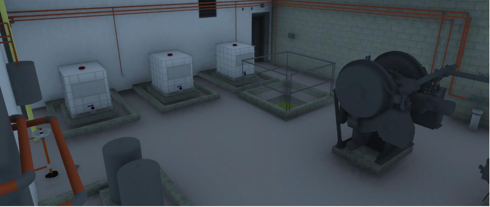
BIM | CIM Collaboration, in general, is a process in which project stakeholders will work together, communicate on progress, issues, etc. with the overarching goal of ensuring that a design is well coordinated. A major component to this level of Collaboration is Model Federation. Model Federation in general has very similar goals, but can also have very purposeful applications and expectations associated with them as well.
While all project team members are chugging away with developing design models for their specific disciplines and specialties using various authoring tools, Model Federation processing is essentially the action of combining all disciple and specialty design models into a “Single Source of Truth”. Once federated, we have an opportunity to further analyze, interrogate, isolate, navigate, and etc., our projects holistically.
As you can imagine, there are many efficiency and time/cost saving benefits to be gained with
AUGIWORLD Magazine | April 2023 augi.com 24 BIM | CIM by:
Stephen Walz
proper Model Federation processing and analysis. As BIM | CIM designs and authoring tools being leverage become more complex, and with higher expectations placed upon project teams to ensure a well-coordinated model is developed and delivered, Model Federation processes are becoming increasingly critical. Some additional benefits of Model Federation have the potential to include the ability to:
• Perform Issue Tracking and Model Coordination tasks
• Perform Model Validation and Design QA/QC
• Surface Metadata and Custom Properties/ Property Sets
• Perform (rough) Cost Estimations
• Perform Quantifications
• Perform additional design and construction analyses as needed
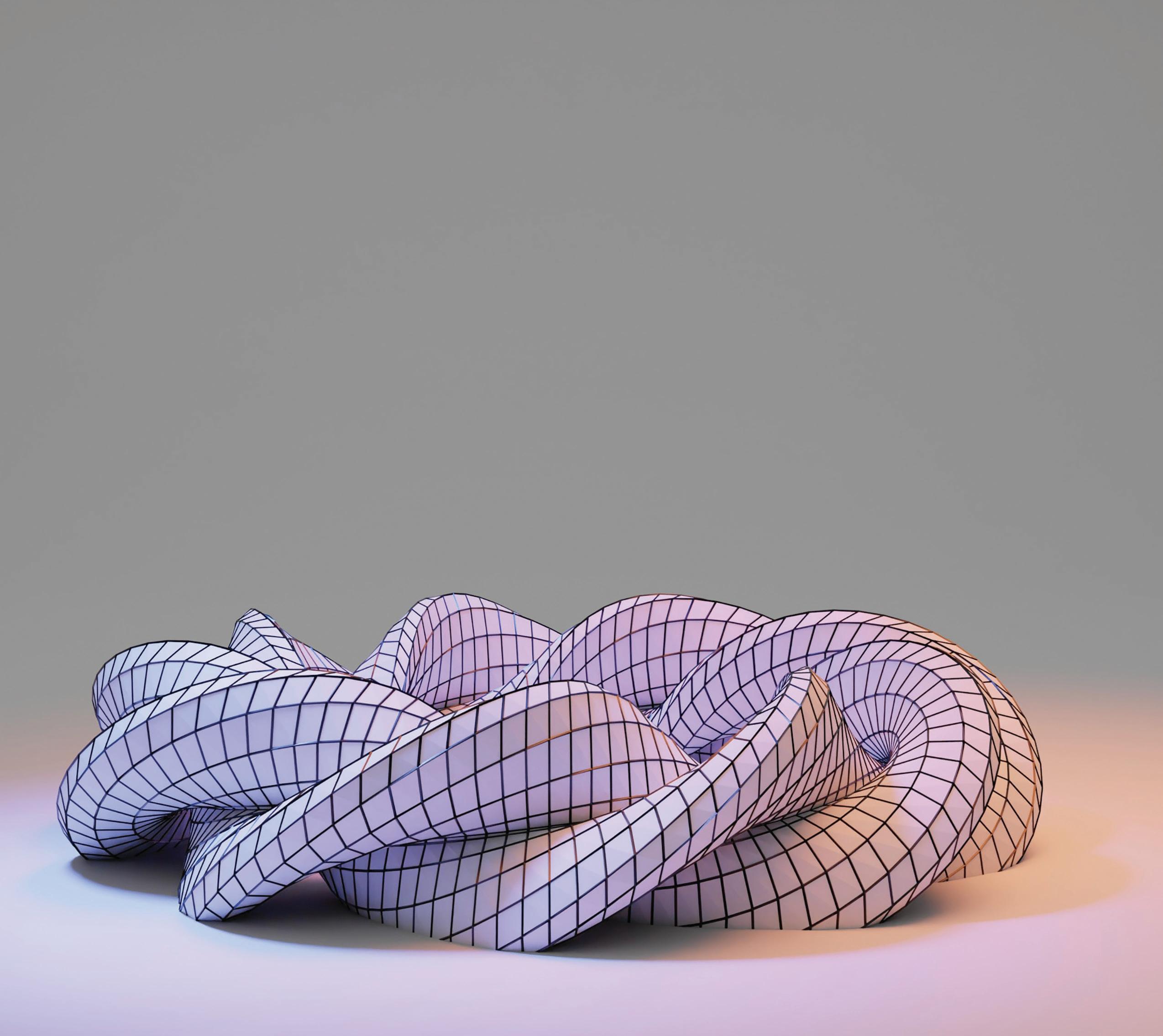
With so many benefits available to us through Model Federation processing and analysis, how could we not want to take advantage of it? Maybe this is another case of it being easier said than done, where design and software complexities can have a tendency to complicate the process for seamless consolidation and ultimately creating that actual “Single Source of Truth” (figure 1).
NAVIGATING THE MODEL FEDERATION LANDSCAPE
Over the past several years, I’ve been on the lookout for a Model Federation process that will support projects containing both BIM and CIM design models that are developed across multiple software
vendor provided solutions (mostly Autodesk and Bentley though). The ideal Model Federation process, in a perfect world, would need to provide value and benefits listed earlier. Additionally, this ideal Model Federation solution would have the ability to be flexible to accommodate BIM and CIM design models generated in atypical design software solutions as well, and with minimal to no data loss through migrations and consolidations.
Note: Understanding a lot of very intelligent people are reading this, if you have any recommendations, or have solved this puzzle already, please don’t hesitate to reach out to me (Stephen.Walz@hdrinc. com)! I’d love to talk through lessons learned and, more importantly, share with the greater AUGIWORLD community your success stories!
In any event, I’ve found that if you sit on the Building, or more specifically Revit, side of the house, you’re probably reading this and saying to yourself: “Yes, these tools and processes absolutely exist. This guy must be navigating with a map from the 1800’s!” In typical fashion across our industry, project teams generating BIM designs in Revit always appears to be sitting pretty at the top, as they (almost) always get the lion’s share of development attention from software vendors. Major vendors, along with new vendors looking to enter the market within the AECOO space, tend to figure out a way of supporting Revit workflows first. That said, we already have many solutions available to us that support Model Federation processes and provide many of the benefits listed earlier, such as:
augiworld.com April 2023 | AUGIWORLD Magazine 25 BIM | CIM
Figure 1
Navisworks, Solibri Model Checker, BIMCollab, etc., etc., etc. (you get the point).
If you sit on the Civil Infrastructure side of the house, whether your using Civil 3D, OpenRoads, Civil Designer, BricsCAD, etc., you may be a little more understanding and compassionate of my struggles along this journey to find that ideal Model Federation solution; although you still may be saying to yourself: “Although there are no direct routes, there are a few detours and roundabout ways that can get you where you want to go!”
Although I’ve had more success with Autodesk in my career, I will say that Bentley’s more recent approach to their Open product line is refreshing to see, as all models and data are (fairly) easily transferrable across the board; but we all know that working in only one vendor provided solution isn’t always achievable. As it relates back to Model Federation solutions and processes on the Civil Infrastructure side…it’s true, we do have several solutions available to us that support Model Federation processes and provide many of the benefits listed earlier, such as: iTwin Design Review, Synchro, InfraWorks, and Navisworks, with each having their own varying levels of integration capabilities, complications/limitations, and benefits.
If you regularly work with both sides of the house, I’m sure you can relate to my struggles and failure to locate such an ideal Model Federation solution that we can use to capitalize on all benefits listed earlier. Even while navigating this journey with a
map from the 2020’s, it sometimes seems that the industry is still pretty far off from developing a practical Model Federation solution that meets all expectations and provides maximum benefits (and is it even cost effective?).
On the bright side, one recently emerging solution that seems to be rapidly rising in this realm is Speckle. Speckle has numerous software connection integrations available to transfer both models and data in a variety of ways. Adding to the fact that integrations have been made with many major BIM and CIM design authoring tools,
AUGIWORLD Magazine | April 2023 augi.com 26 BIM | CIM
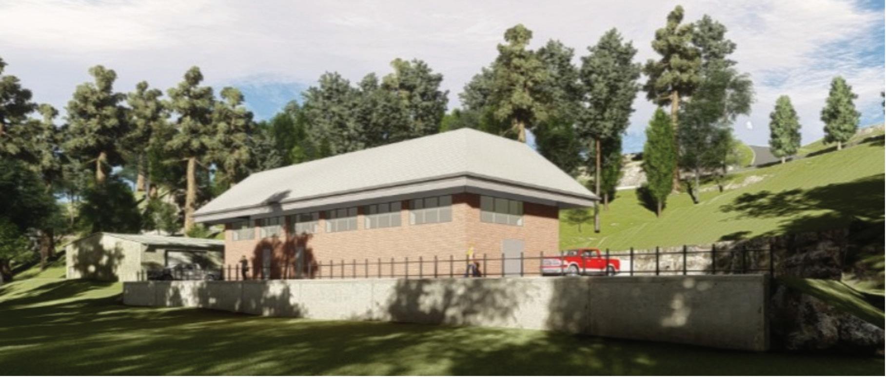
Figure 2
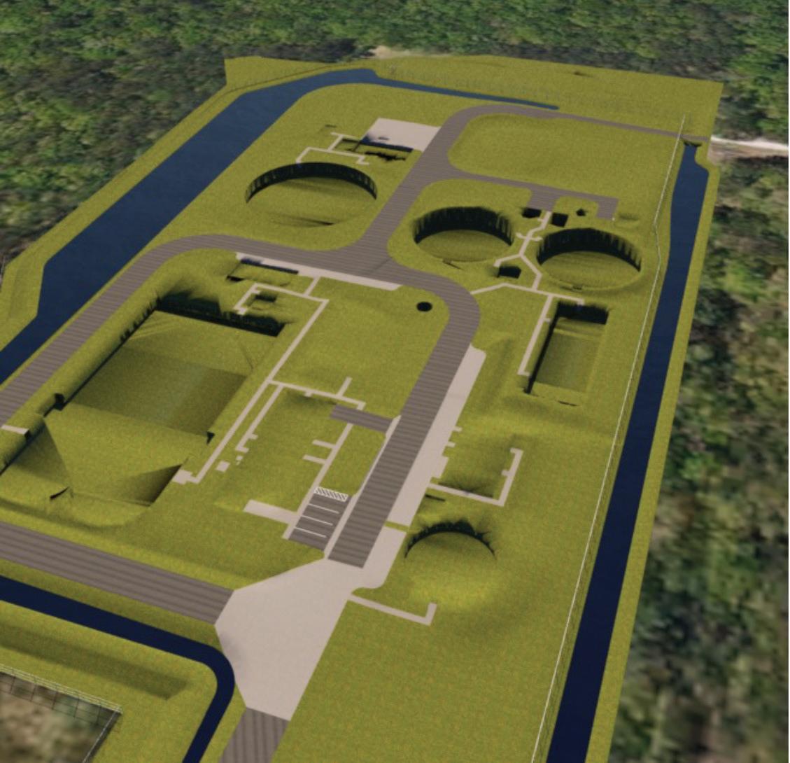
Figure 3
it’s worth noting that Speckle (at this point) is an opensource solution, making it highly customizable.
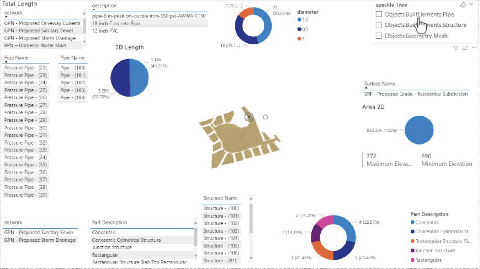
I’ve been putting Speckle through the paces over the past couple months and feel that I’ve made a ton of progress to merge both sides of the house leveraging just out-of-the box Speckle connections, although workflows are still a little disjointed. That said, I’m encourage by the fast-track that Speckle is on and have a feeling that we are on the verge of bigger and better things near term…we may just need to learn a bit of coding to get us where we need go (or maybe that’s what OpenAI and ChatGPT are for???).
CONCLUSION
Although it took a while to get here, I am encouraged by the recent “Open” -ness of technology solutions making their way presence known in our industry, and many of us sharing knowledge and lessons learned as we try to figure out how best to extend those capabilities and integration. That said, there definitely is some very noticeable momentum going on across the AECOO space in general to increase model and data migrations seamlessly, which will greatly benefit our Collaboration efforts and Model Federation processing and analysis as a whole.
Stephen Walz is, not only the BIM | CIM Content Manager for AUGIWORLD Magazine, but also the Digital Design Lead within HDR’s Applied Technology Office, a global leader in Engineering, Architecture, Environmental and Construction services. Stephen has been in the AEC Industry since 2003, and with HDR since 2004 supporting multiple offices and regions and now supports all Business Groups and Market Sectors across HDR at a corporate level. In Stephen’s current role, his primary focus is to work with HDR’s Business, Technical and IT Leadership, as well as our technology vendors, to identify, evaluate and implement new platforms/tools/technologies supporting BIM | CIM processes and workflows, drive consistency with how HDR is leveraging various tools and platforms, and identifying ways to build skillsets and overall awareness across HDR to better serve their clients. Stephen can be reached for comments or questions at Stephen.Walz@hdrinc.com or subscribe to his YouTube Channel for BIM | CIM, Data Integration, and Visualization workflow video demonstrations.

augiworld.com April 2023 | AUGIWORLD Magazine 27 BIM | CIM
Figure 4
Project Housekeeping
Picture yourself on holiday or vacation. You are having a great time, away from the cares of the workday. You spend time with loved ones or friends, relaxing or hiking, or doing whatever you please. You are relaxed, unstressed, enjoying life, maybe at a distant tropical resort or mountain lodge… Then you get a knock on your hotel door. Someone on the other side says, “Housekeeping!” You think for a minute… Did I need more toilet paper, the room freshened up, the trash dumped, or the minibar restocked? Is this someone coming to tidy up or is it something unexpected, dark, and disruptive?
That was a nice lead into my topic. Sounded like the plot of some cheap thriller. But how often do we think about housekeeping? In the tech world, probably not as much as we should. How much dust

has collected on your data? What mold is growing on your installs? What grime has settled into your systems?
Back in April of 2021, I wrote about retiring old technology that was no longer used. I wrote about how we hang on to old tools that no longer meet our needs. I spoke of getting others to get rid of old tech. Now I am going to talk about housekeeping. Project archiving is critical, and it gets forgotten all the time. The things that are easily forgotten because they are low priority and you have moved on to other things. But when you forget to clean up, the clutter starts to build up. I am not telling you something you don’t already know, just reminding you so you can make it happen. Time for some housekeeping on our project files and servers.
AUGIWORLD Magazine | April 2023 augi.com 28
by: Mark Kiker Tech Manager
BACK UP
First, I back all the files up. Not much to say on this. You know you back things up, but I am talking about a specific archive of all files related to a project, not the general recovery backup that happens all the time. A specific total backup of all the project files, even the junk, can ensure that nothing gets lost. Back it up as soon as the files and output go out the door.
SPRUCE UP
If you look up the entomology of the term “spruce up” you find that the word “spruce” was used in the 1500’s for the area known as Prussia. In that region they created finely crafted goods that were embraced by the rich. The term Spruce was soon expanded to mean anything that was fashionable or neat in appearance. So, sprucing up the project means making it neat in appearance. I do that by creating a good snapshot of the docs.
When the backup is done, I make a final submittal folder and copy all of the final deliverable documents in there and only the final documents. I COPY them (do not move the originals). This is a snapshot in time of the design docs as they were provided to the client. It is clean and contains nothing but the files needed to produce the final output. It might be PDF copies of hardcopy deliverables, and/or copies of the design files, but it is exactly what was given to the client as the design deliverable. If the client does not get the digital files, I still make this copy for in-house use.
CLEAN UP
Now on to the rest of the project files. Sometimes things just need to be cleaned up a little. In the heat of a project, things can get chaotic and cluttered. I have used a process of project closeout that goes back through the files and data and gets rid of the things that are not germane to the final design. I straighten up the AutoCAD design files by running Purge, Audit, OverKill and the like. For Revit it might include Audit/Detach, Purge unused, Resolve Warnings, and more. You get the idea. Just sweep away the clutter in the files.
Remove any files that have words like “copy” in them. And those that are “temp” or maybe have a personal name and number after them (“Hank- save234”), like the ones created in the heat of battle to try things out or save some unused design concept.
STRAIGHTEN UP
Now for the project folders. I go back into the original folders and straighten things up. I look for design iterations that did not come to pass. Design options that did not make the final cut. I don’t just delete them unless the PM says that I can. If they are total junk that is never needed again, just delete them (you have the backup from the beginning of this process – right?). Then remove them from the final project folders.
You should also make sure that the folder names indicate what is contained in them. This may sound obvious, but along the project road there are detours that end up in randomly named folders like “Option 2”. Then Option 2 becomes the main project folder and is never renamed. It is time to fix all of that. Go through every folder to make sure it reflects the content and that the content is still part of the main project. If it is not, move it to an archive folder.
This leaves a clean project structure ready for future change orders, additional design work or whatever. You know you will come back again to change orders and such. Straighten it up before that starts happening.
CHEER UP
Your project housekeeping is done. Now the project is looking cleaner. You can move on to the next big thing. The project is ready if needed later. If the client wants additional work, your team is ready to hit the ground running. Now, go relax.
Mark Kiker has more than 30 years of hands-on experience with technology. He is fully versed in every area of management from deployment planning, installation, and configuration to training and strategic planning. A former AUGI Board member, President, and Executive Director, he is an internationally known speaker and writer, having written for AUGI World since 2015. Mark is currently serving as Chief Technology Officer for SIATech, a non-profit public charter high school focused on dropout recovery. He maintains two web sites, www.caddmanager.com and www.bimmanager.com.

augiworld.com April 2023 | AUGIWORLD Magazine 29 Tech Manager
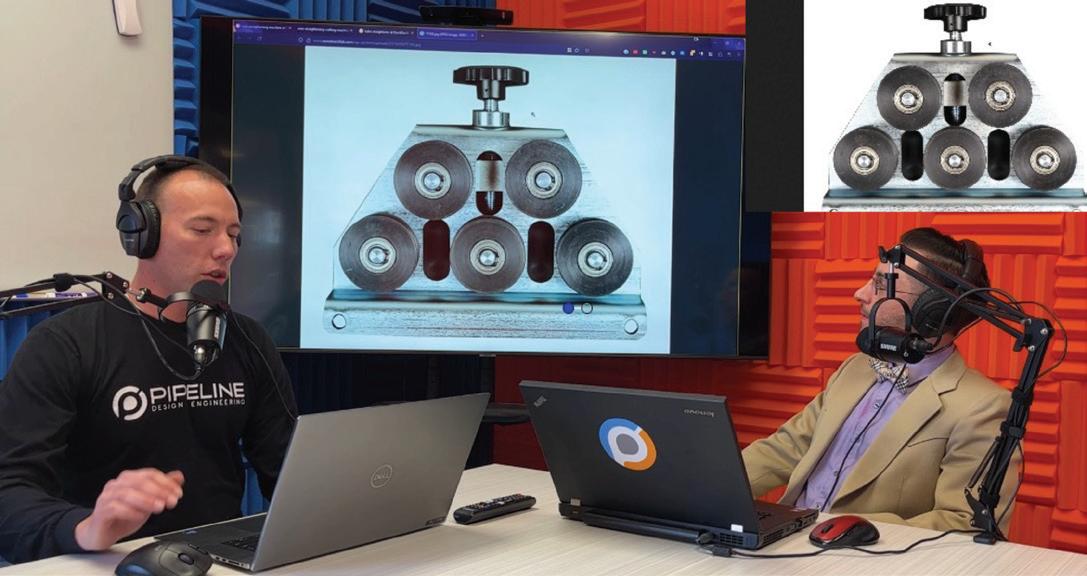
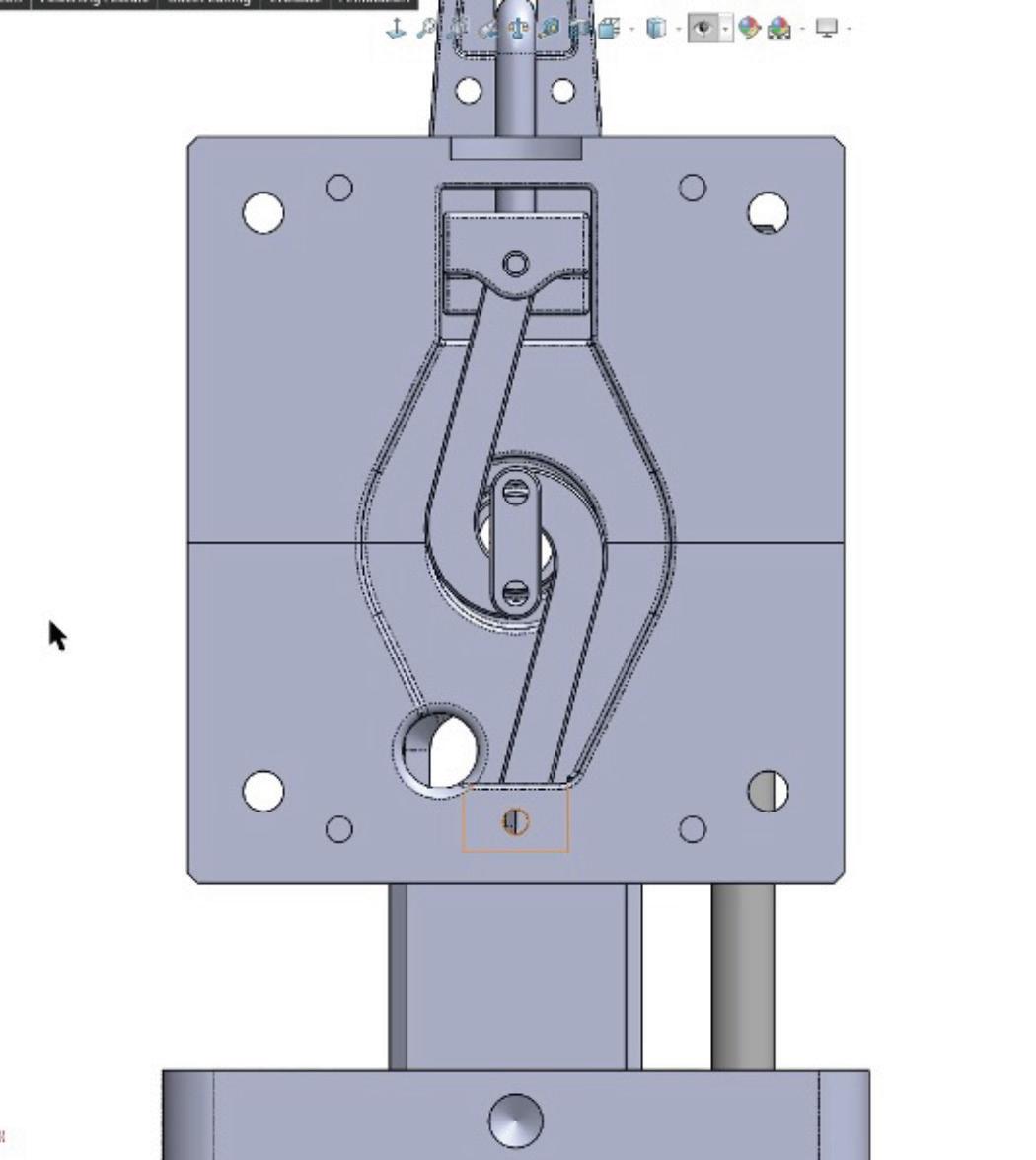
Mechanisms & Mentorship: Symmetric OverCenter Clamping Mechanism
THIS ARTICLE IS BEST READ AND VIEWED IN THE ELECRONIC VERSION OF AUGIWORLD
https://youtu.be/IPv4SJR1LEk
Ever wondered what it would be like to be mentored one-on-one by a Senior Engineer that’s using SOLIDWORKS to successfully deliver solutions to industry clients? My name is Rafael Testai, and in this video series Mechanisms & Mentorship, we’ll take a look behind the scenes to see how a hand-picked Engineer has designed one of their mechanisms in granular detail. We’ll “open the hood” to analyze their CAD design and thought process behind the solution. I’ll ask them questions about the project, roadblocks, challenges, specific insights they learned, and how they’re using SOLIDWORKS to solve real world problems.
You’ll learn a mixture of soft skills and hard skills. This series is perfect for viewers who are already proficient in SOLIDWORKS (CSWA, CSWP, CSWE) and want to take the next step in their careers.
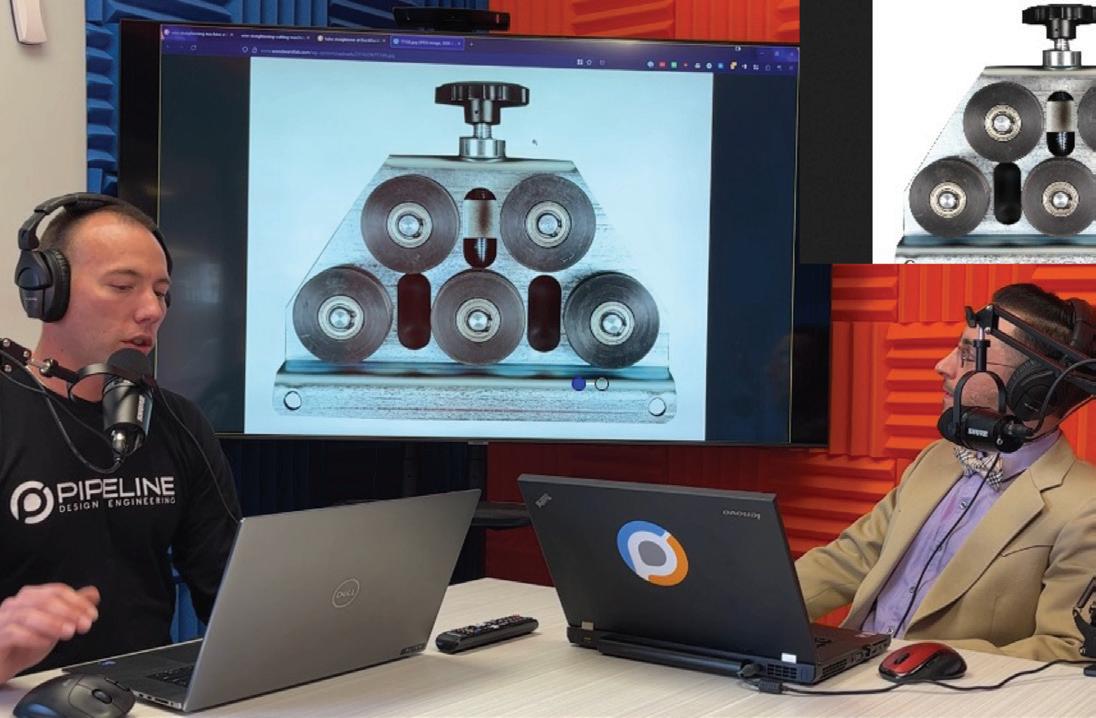
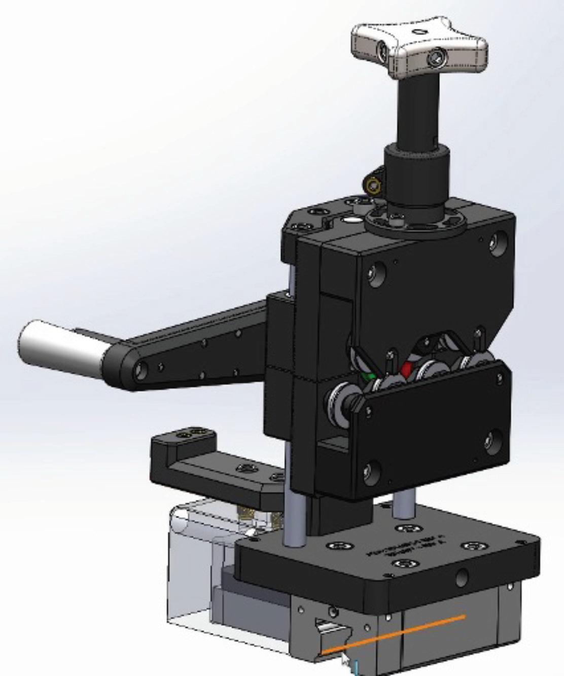
In this episode of Mechanisms & Mentorship, I’ll interview Senior Product Development Engineer, John Martell from TeamPipeline.us in Arizona. We’ll focus on the clever mechanism that he designed called “Symmetric Over-Center Clamping Mechanism.”

AUGIWORLD Magazine | April 2023 augi.com 30 Solidworks
Testai
by: Rafael
TIME STAMPS
What Problem Were You Trying to Solve? (Min 1:07)

The customer had a medical device that was similar to a straight wire. After usage, the medical device had bends. The customer wanted John to design a fixture that would straighten the wire in the medical device, so that it could be reprocessed and reused again. (Give this video a thumbs up if you’re in favor of sustainability and reprocessing devices to minimize our waste).
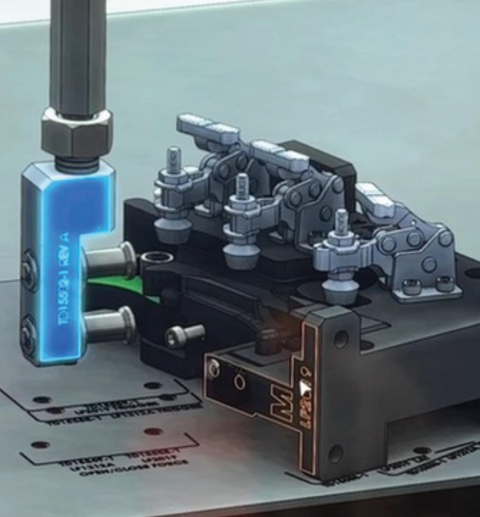
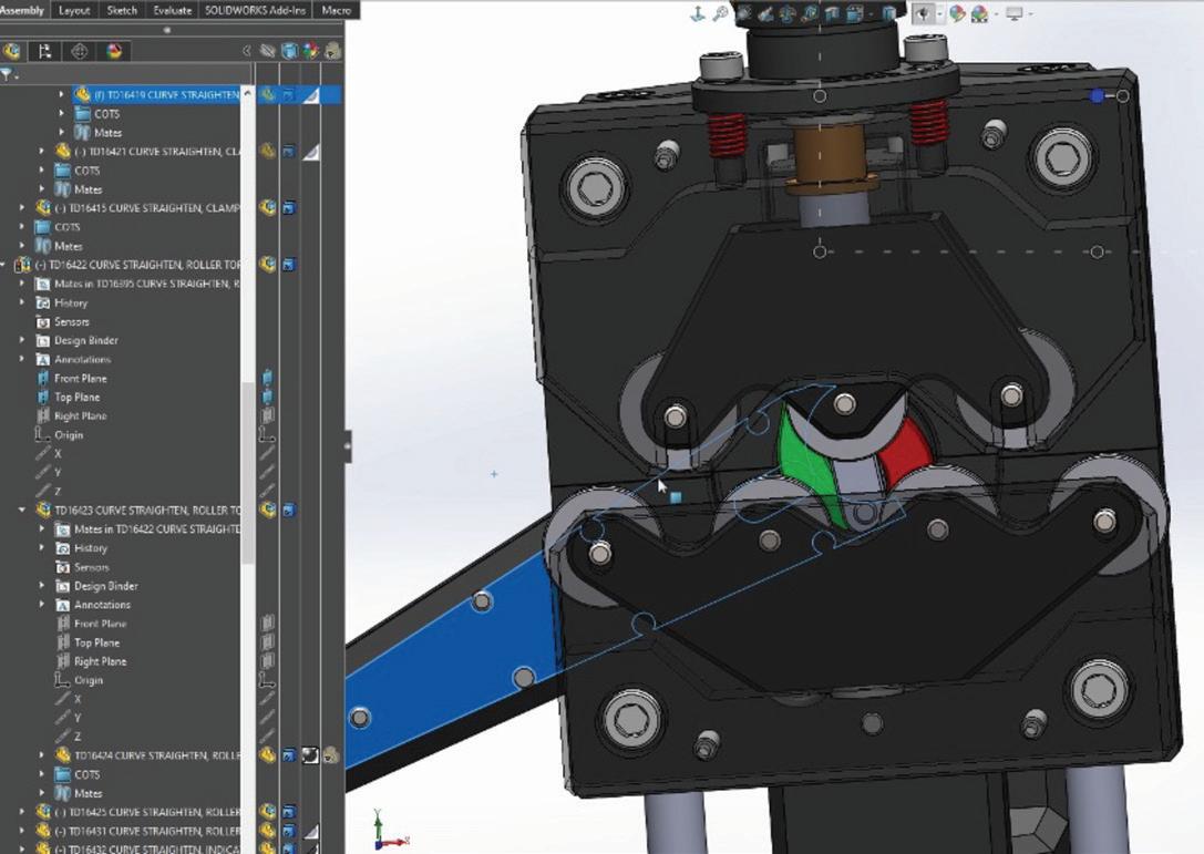
Big Picture Mechanism Explained (Min 1:38)
PRO TIP: Look at Existing Off the Shelf
Components (Min 6:36)
Start by gathering requirements that the customer gives you. Then, look for inspiration on how to solve the problem at hand by looking for off the shelf straightening devices that already exist.
augiworld.com April 2023 | AUGIWORLD Magazine 31 Solidworks
When to Use a Sketch Notebook and Why? (Min 10:30)
Part of John’s process in mechanical design engineering is using an actual pen and paper notebook to jot down ideas, requirements, visualization, mechanisms, and track project progress. He explains that his brain feels optimally engaged when using this medium to flesh out ideas. Though there are perks of OneNote and similar electronic notes apps, and it is very useful
at certain points in a project, John shared that he prefers paper and pen over a tablet. Do you agree?

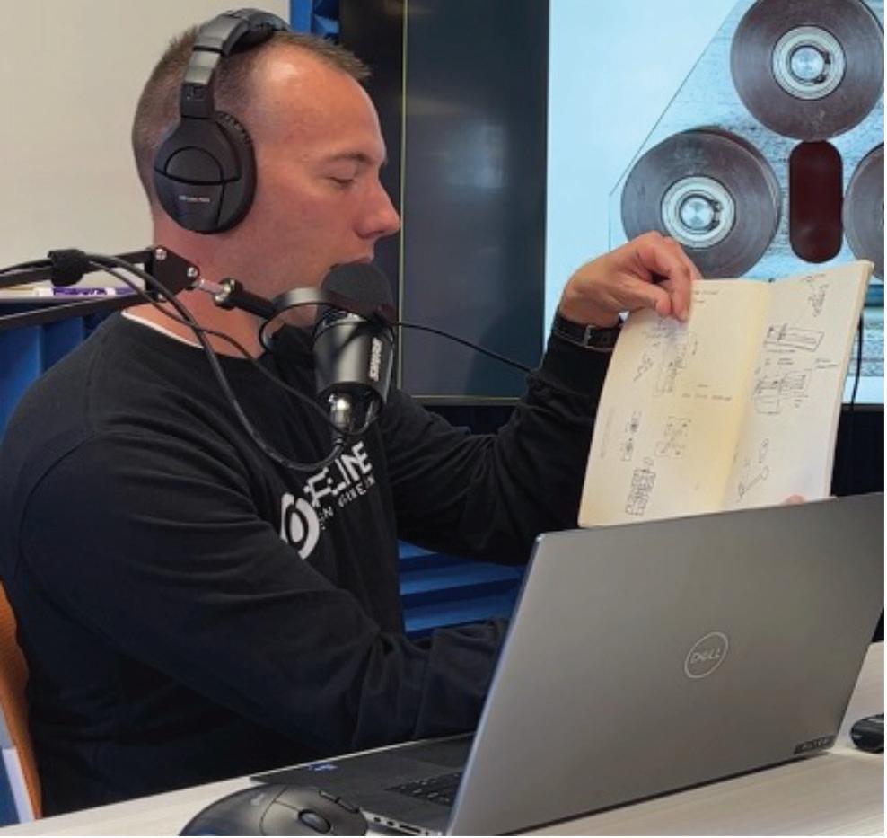
What are your preferences?
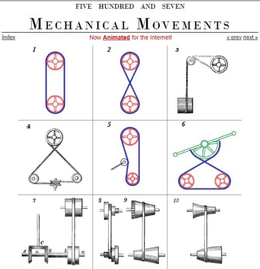
Borrowing inspiration from existing mechanisms and devices (Min 18:38)
John explains that getting acquainted with as many mechanisms as possible will help you in your journey as a mechanical design engineer. This knowledge will result in doing less

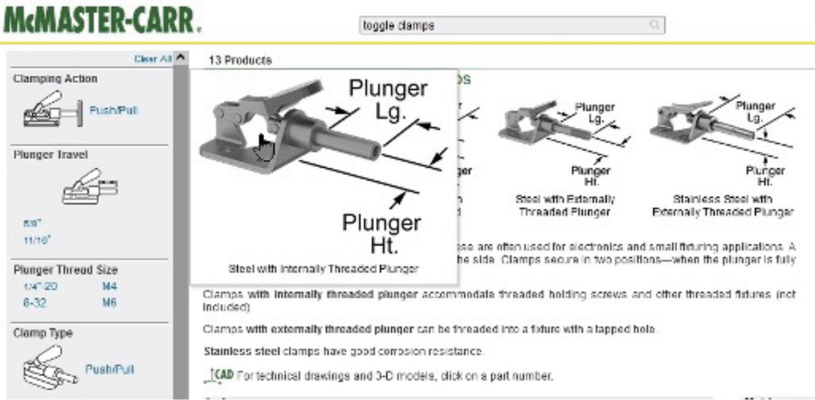
AUGIWORLD Magazine | April 2023 augi.com 32 Solidworks
development in designs. He references the websites http://507movements.com/ and McMaster-Carr as sources of inspiration.
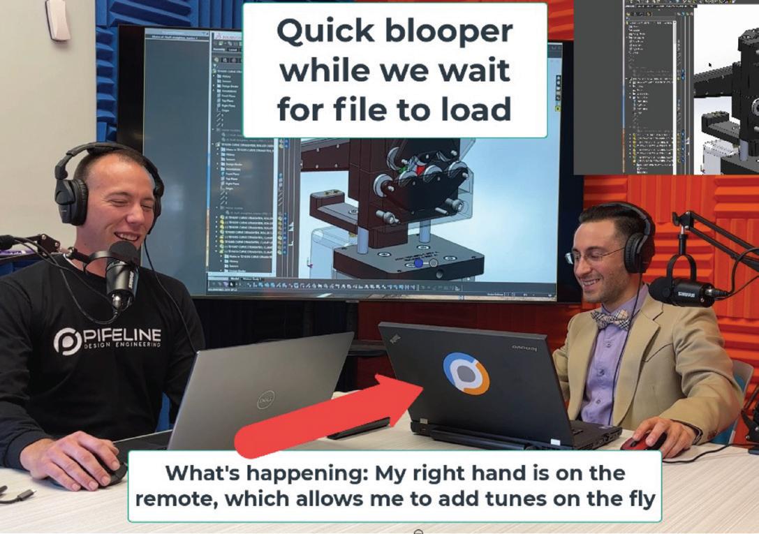
BONUS #1: Blooper (Min 16:50)
BONUS #2: Fun fact
Did you know that John Martell is a musician and has over 2 million listens from the songs he has created and published on Spotify? Listen to his Verified Spotify artist profile at https://open.spotify. com/artist/3XXaMkkjWhGq77BBIk3a5r?si=oqgW1kj KQ0GqADtCzxKQfQ&nd=1. In addition, John created the intro audio track for the “Being an Engineer” podcast, which is ranked as the #1 and #2 podcast on Google for the terms “Mechanical Engineer Podcast” and “Mechanical Engineering Podcast.” How many of you are engineers and also enjoy

playing music? Comment below. Now may be a good time to connect with each other.
To learn more about John Martell, visit his LinkedIn profile at linkedin.com/in/johnbmartell

If you read until the very end, I greatly appreciate it. I would encourage you to follow me on Linkedin so that we can stay in touch, and you can be notified when more articles get published. I lead with value and my writing style is direct and to the point. https://www.linkedin.com/in/testai/
Any recommendations on who you think I should interview next? Feel free to reach out to me on Linkedin or Instagram. I read all correspondence. Linkedin: https://www.linkedin.com/in/testai/ Instagram: https://www.instagram.com/rafael_testai/
Rafael Testi is a SolidWorks Influencer. Follow to watch exclusive videos he creates that quickly teach you the inner working mechanism of interesting products l Mechanical Product Designer LinkedIn/Instagram/TikTok/ Podcast/ More articles: https://linktr.ee/testai
augiworld.com April 2023 | AUGIWORLD Magazine 33 Solidworks
Civil 3D Labels: Express Yourself with Expressions!

One of my favorite things about Civil 3D are the dynamic labels. Once upon a time, you had to manually label every contour, every pipe, every road, every structure in plan view and profile view. Even scarier, you had to remember to revise those labels in plan view AND profile view if something changed. Fortunately, things don’t change very often in our industry. Right?
Wrong! Design is fluid and changing constantly. Civil 3D label styles allow the labels to change with the design dynamically.
Creating expressions to use in your C3D label styles is a fun way to customize your labels. I will demonstrate how to use expressions to change the size of text depending on the viewport scale, to only show certain labels based on the viewport scale, and to label pressure part inverts.
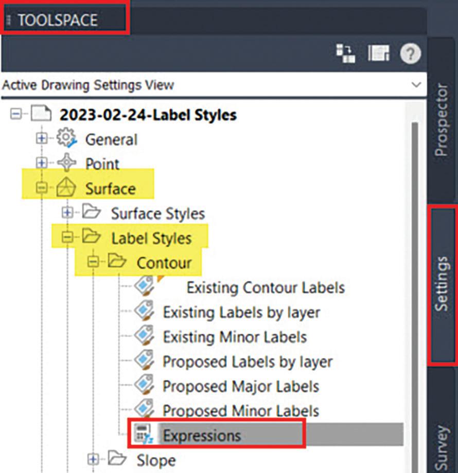
WHERE ARE EXPRESSIONS CREATED AND STORED?
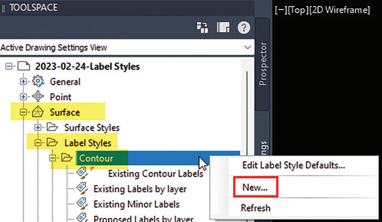
Expressions for each label style are located in the Settings tab of the Toolspace under each Label Style that allows expressions. Figure #1 below shows the Expressions location for Surface Contour Labels.
AUGIWORLD Magazine | April 2023 augi.com 34 Civil 3D
by: Meredith Chamberlain
WHAT MAKES UP AN EXPRESSION?
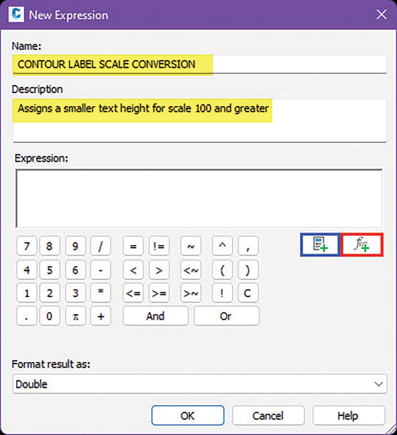
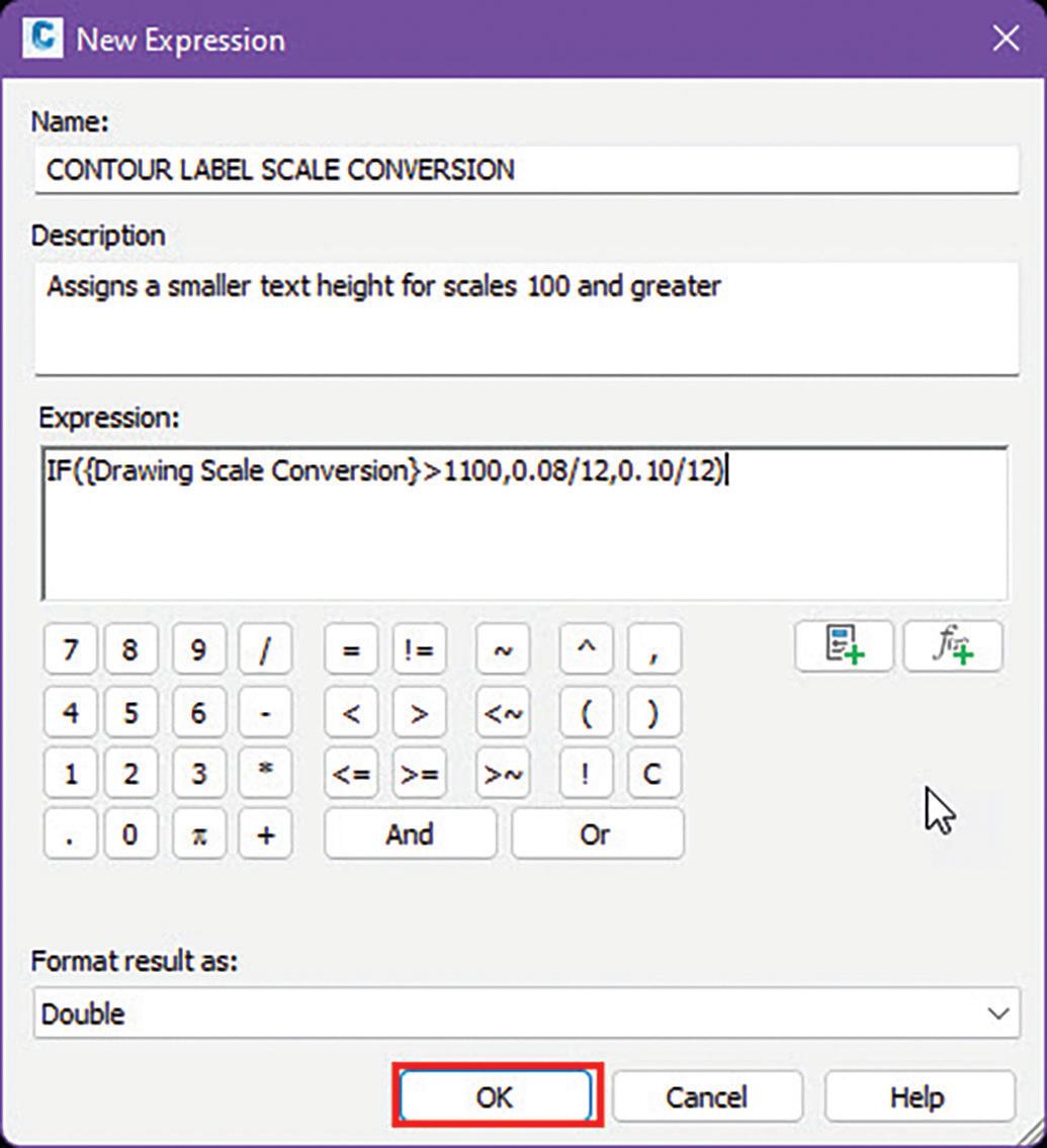
Figure #2 shows the New Expression dialog box.
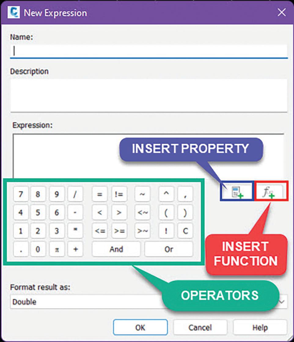

A Civil 3D label expression is created using some or all of the following components:
• Feature Property (added using the Insert Property button outlined in blue). These are the properties associated with the feature type such as Surface Elevation for surfaces or Alignment Name for alignments.
• Function (added using the Insert Function button outlined in red). There is a comprehensive selection of mathematical, logical, and other types of functions.
• Operators (outlined in green).
EXPRESSION EXAMPLE #1
Let’s create an expression to change the size of text depending on the scale of the viewport and then use the expression in a label style.
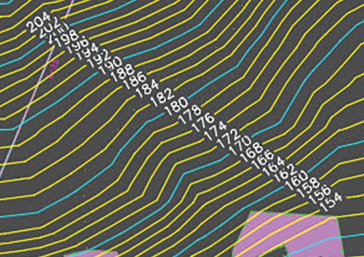
One example where this may come in handy is for surface contour labels. At 50 scale, a standard text height of 0.10 might be fine, but at 100 scale, that standard text height might create overwrites.
augiworld.com April 2023 | AUGIWORLD Magazine 35 Civil 3D
Figure 1
Figure 2: New Expression Dialog Box
Figure 3: Surface contour labels at 1”=50’
Figure 4: Surface contour labels at 1” = 100’
Step 1: Define the Expression’s Purpose
Expression purpose: If the viewport scale is 1” = 100’ or greater, the text height should be 0.08. If the viewport scale is less than 1” = 100’, the text height should be 0.10.
Step 2: Create the Expression
1. Open the New Expression dialog box.
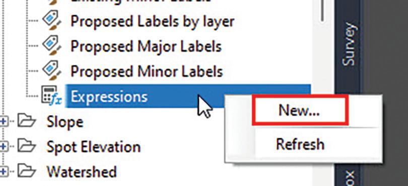

• Right click on the Expressions setting for Surface Label Contours. (See Figures #5 & #6 below).
• Click “New” to bring up the New Expression dialog box.
2. Assign a name and fill out the description (optional) of the expression as shown in Figure #7.
3. Create expression.
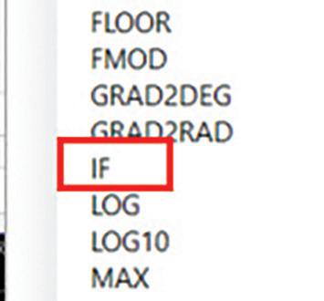
• Click on the Insert Function button to reveal the list of functions and choose the IF function.
• The Expression Editor populates with the function.

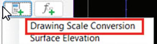
• Click on the Insert Property button to reveal the list of properties for this feature. Choose “Drawing Scale Conversion”.

AUGIWORLD Magazine | April 2023 augi.com 36 Civil 3D
Figure 5
Figure 6
Figure 7
Figure 8
Figure 9
Figure 10
• Drawing Scale Conversion = Viewport Scale*12
• Create the expression shown in Figure #11.
• Hit OK on the New Expression dialog box to finalize the expression and to add it to Toolspace.
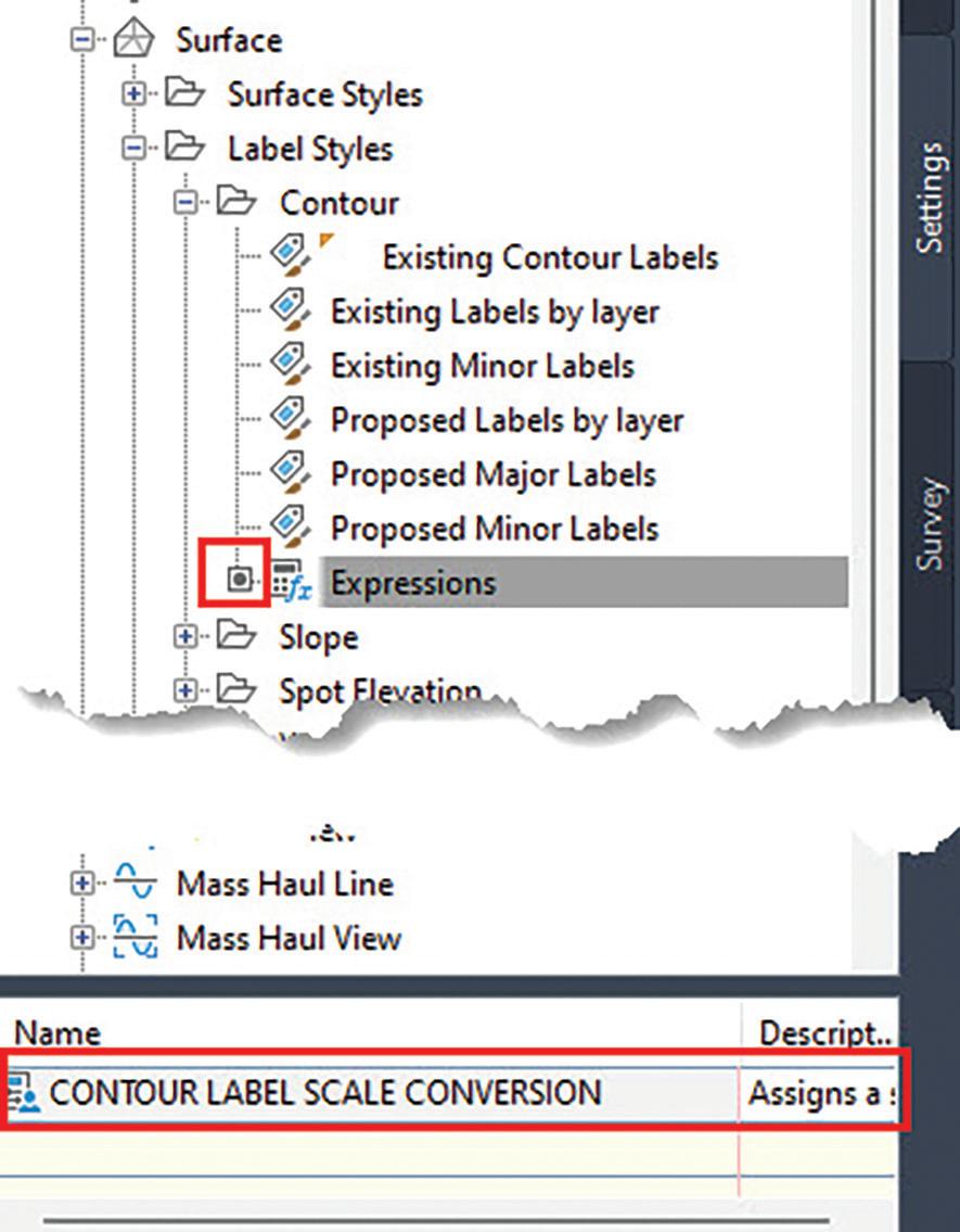
• The expression has been added and appears at the bottom of Toolspace (figure 13).
Step 3: Understanding
the Expression
Remember our original expression purpose?
If the viewport scale is 1” = 100’ or greater, the text height should be 0.08. If the viewport scale is less than 1” = 100’, the text height should be 0.10.
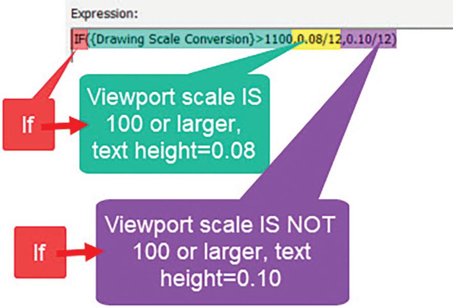
• Here is our expression: IF ({Drawing Scale Conversion}>1100,0.08/12,0.10/12)
Translation: If the viewport scale is 1” = 100’ or greater, then the label text height will be 0.08. If the viewport scale is NOT 1” = 100’ or greater, then the label text height will be 0.10.
augiworld.com April 2023 | AUGIWORLD Magazine 37 Civil 3D
Figure 11
Figure 12
Figure 13
Figure 14
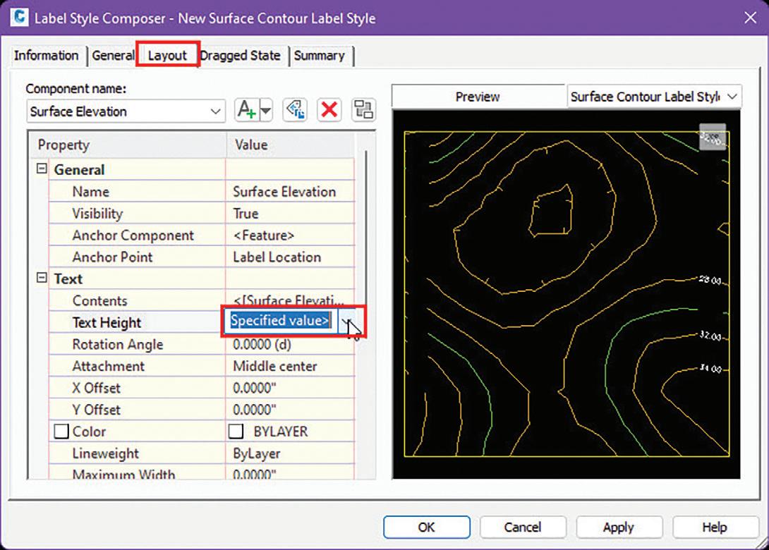
Step 4: Use the Expression in a Label Style
1. Create a new Surface Contour label style or copy an existing Surface Contour label style in the Settings tab of the Workspace.
3. Hit OK on the Label Style Composer.
4. Apply the new Surface Contour Label Style to your surface contour labels.
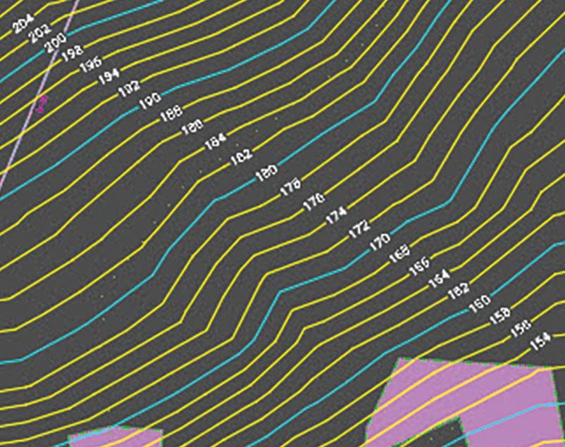
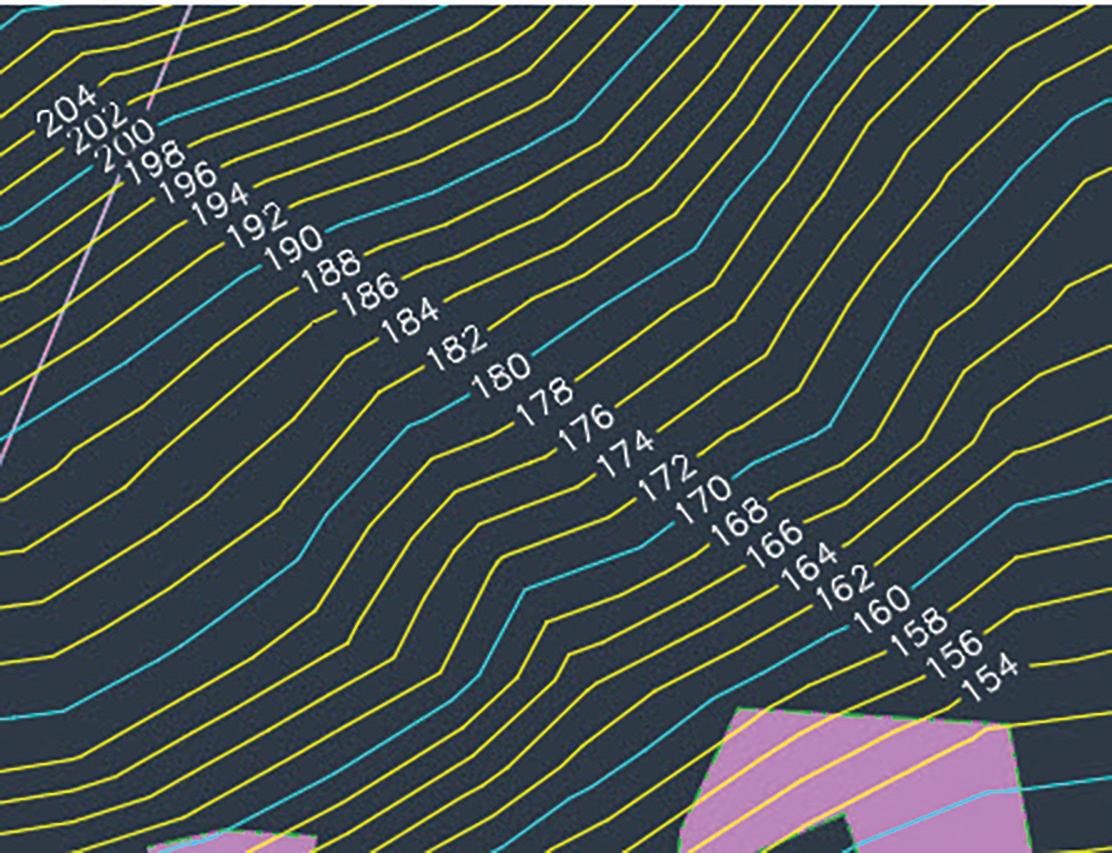
Figures #18 and #19 show the same area at 1” = 100’. Figure #18 uses the original text height of 0.10. Figure #19 uses the new expression to change the text height for 1” = 100’ to 0.08.
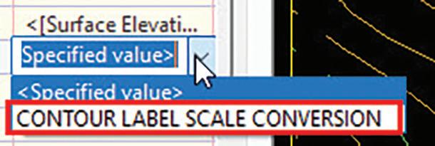
2. On the layout tab, click the value for Text Height. There is now a drop-down menu since we have added the expression. On the drop-down menu, select the expression name you just created.
OTHER EXPRESSION IDEAS
Here are a few other ideas for expressions to get you started.
1. Create an expression that shows only major contour labels (for 1’ & 5’ or 2’ & 10’ minor and major intervals).

AUGIWORLD Magazine | April 2023 augi.com 38 Civil 3D
Figure 15
Figure 16
Figure 17
Figure 18: Text height of 0.10.
Figure 19: Text height of 0.08 from expression.
a. Expression purpose: Only major contour labels appear.

b. Expression:
IF (FMOD ({Surface Elevation},5) = 0,0.10/12,0)
c. Understanding the expression: If the Surface Elevation divided by 5 yields a remainder of 0, then the text height should be 0.10. If the Surface Elevation divided by 5 yields a remainder other than 0, then the text height should be 0.
Therefore, 5’ and 10’ contour labels will have a text height of 0.10 while 1’ and 2’ contour labels will have a text height of 0 so they will not show.
You might wonder why bother? You can set it in the properties to not show the minor contour labels. But what if you wanted to see the minor contour labels in 50 scale but not 100 scale?
See if you can combine the two expressions we have covered to create an expression that shows only major contour labels for drawings with a viewport scale of 1” = 100’ or greater.
2. Create an expression to label the invert of pressure network fittings.
a. Expression purpose: Label pressure network fitting invert. An expression is necessary because Civil 3D only gives the insertion point elevation which is the vertical center of the fitting.
b. Expression: Must create a separate expression for each pipe diameter.
Expression Name: INV-12”
{Insertion Point Elevation}-0.5
Expression Name: INV-6”
{Insertion Point Elevation}-0.25
CONCLUSION
The power of Civil 3D is not just in its design, but also its ability to help us create the documentation of that design which is where Civil 3D labels come into play. There are many tools available in Civil 3D to enable you to leverage your labels to be more knowledgeable, more efficient, and more informative. The use of expressions is just one of those tools.
Can you think of other expressions you could create? I would ask yourself first, “What information do I want in my label?” Then explore expressions to see if you find an answer there. If you don’t, move onto the next tool in your labeling arsenal.
Have fun expressing yourself!
Ms. Meredith Chamberlain is an Autodesk Certified Professional in Civil 3D for Infrastructure Design. Meredith is the CAD Manager for Morris & Ritchie Associates, Inc., a full-service planning, architecture, and engineering services firm with 8 offices in the mid-Atlantic and North Carolina. During Meredith’s almost 17 years at Morris & Ritchie Associates, Inc., she has advanced from an entry-level CAD drafter to the CAD Manager. Meredith founded and ran the Baltimore Washington Civil 3D User Group from 2015 to 2019. With an education background in chemical engineering and experience in furniture production, Meredith has a key focus on efficiency and process streamlining. This focus is combined with a creativity to think outside the box to develop protocols that are unique and efficient. Most importantly, she loves AutoCAD & Civil 3D!

augiworld.com April 2023 | AUGIWORLD Magazine 39 Civil 3D
Bright Ideas for a Bright Future
AUGIWORLD brings you the latest tips & tricks, tutorials, and other technical information to keep you on the leading edge of a bright future.