23 minute read
CROSS-LAMINATED TIMBER PANEL CONSTRUCTION
Next Article

ACTA FACULTATIS XYLOLOGIAE ZVOLEN, 61(2): 109−119, 2019 Zvolen, Technická univerzita vo Zvolene DOI: 10.17423/afx.2019.61.2.11
CHARRING LAYER ON A CROSS-LAMINATED TIMBER PANEL CONSTRUCTION
Katarína DúbravskáDominik Špilák - Ľudmila Tereňová – Jaroslava Štefková
ABSTRACT
When the wood is thermally loaded, the microscopic changes of wood structure and macroscopic changes appear and are examined. The macroscopic changes include formation of char layer on the surface of the wood-based material. The main aim of the medium-scale test is to assess the char layer formation on the surface of the sample under thermal loading. The test sample was made of CLT (cross-laminated timber) panel with no surface treatment with the dimensions of 1000 × 1500 × 80 mm. It was a 3-layer panel made of spruce lamellas. The test sample underwent a medium-scale test during which it was exposed to a radiation panel for 40 minutes. Intensity of the radiation panel was 43.1 kW·m2. During the test, the temperature on the exposed side of the test sample was recorded by a thermocouple. The test sample immediately began to degrade and char. After complete charring of the CLT panel layer on the exposed side, its rupture and consequent falling off appeared. The middle layer of the CLT panel was minimal, only in the area where the outer layer fell off. The results of the medium-scale test were compared to the results of the simulation which were achieved from the Ansys 18.1 program. When the medium-scale test and simulation results were compared, some differences were found. The main difference was found when the char layer fell off from the CLT panel and further charring into the depth of the sample followed in the medium-scale test. Keywords: cross-laminated timber panel, char layer, medium-scale test, Ansys 18.1 program simulation.
INTRODUCTION
Cross-laminated timber panel (CLT panel) is considered a large-area material. As stated by ÖSTMAN et al. (2018), this material is classified into D-s2,d0 or Dfl-sl reaction to fire class depending on thickness and density. It is then a combustible material which burns on the surface, releases heat and as so it develops fire and forms smoke according to FRANGI et al. (2009). They also state that CLT panel performance under a thermal load is characterized by fire performance of the individual layers. The significant changes can be observed on its surface by KUČEROVÁ et al. (2009). By OSVALD (2015), a significant macroscopic change, which can be observed, is formation of a char layer which is formed on the surface during a thermal load of the wood by OSVALD (2011), LEŠKO and LOPUŠNIAK (2015), KUKLÍK (2005). This process (KAČÍKOVÁ et al. 2006) starts temperatures higher than 250°C. The char layer form cracked black layer, which has worse thermal conductivity and
slows down the transfer of heat into deeper layers (PAULĎURO and KAČÍKOVÁ 2014). The fact that the char layer functions as an insulation layer and slows down degradation of the remaining cross-section material is also stated by FONSECA and BARREIRA (2009).
As stated by ÖSTMAN et al. (2018), charring of the CLT panel can be different from the charring of the homogenous wood panel due to the method of gluing the individual layers together and due to bonding between the wood layers (local increased charring). The charring of the CLT panel is not influenced by orientation of the layers, in particular parallelly or perpendicularly to the whole panel orientation (FRAGIACOMO et al. 2013). When a CLT panel is thermally loaded, two situations can appear (FRANGI et al. 2008): - Char layer does not disaffiliate. If the exposed layer of the CLT panel is charred in the whole depth and remains at the place, it works as heat insulation of the remaining layers of the CLT panel. - Char layer disaffiliates. If the char layer of the exposed side of the CLT panel disaffiliates, it does not protect the remaining layers against the effects of the fire and charring of the internal layers takes place. The process of charring progresses faster as a result of a higher temperature of the flame. This process is similar to increased charring which can be observed at the protected wood surfaces after disaffiliation of fire cladding.
The effect of the kind of adhesive bonding the individual layers of a CLT panel was dealt by MENIS (2012), FRIQUIN et al. (2010), KLIPPEL et al. (2014). If the individual layers of CLT panel are bonded by PUR adhesive, the falling off of the char layer occurs rather often. This was also observed by KLIPPEL et al. (2014) and MENIS (2012).
Disaffiliation of the char layer (FRANGI et al. 2009) is influenced by the position of the panel (vertical or horizontal), thickness of individual layers, and adhesive performance at elevated temperatures.
The aim of the paper is evaluation of the CLT panel under thermal load and evaluation of the char layer formed at the construction made of CLT panel. At the same time, the results achieved by the medium-scale test shall be compared to the results of the Ansys 18.1 program simulation.
EXPERIMENTAL
Methodology of a medium-scale test The test sample was made of cross-laminated timber with no surface finish. It was a threelayer panel whose individual layers were made of spruce wood with the moisture content up to 12% (± 2%). The panel´s dimensions were 1000 × 1500 × 80 mm. The thickness of outer layers was 20 mm and the middle layer was 40 mm thick. The weight was defined as 5,0 kN·m3 according to DIN 1055-1:2002 for static calculations. The density of the sample was approximately 470 kg·m3. The manufacturer states the material is classified as D-s2,d0 class of Reaction to fire by the Decision of the European Commission 2003/43/ES.
The sample was loaded by a radiation panel for 40 minutes. The sample was placed in distance of 200 mm from the radiation panel. This distance equals the radiation intensity of 43,11 kW·m2 for the radiation panel in the size of 480 × 280 mm. The energy supply for the ceramic radiation panel was propane -butane gas of a constant flow.
The macroscopic change, particularly, formation of the char layer on the surface, was observed during the medium-scale test. Methodology of the simulation To observe the CLT panel behaviour under thermal load, the finite element computational
method of Ansys 18.1 was used. The simulation was set for the change of material properties according to STN EN 1995-1-5 (2008), while different properties of wood along the fibre and across the fibre were taken into the consideration. The mechanical loading consisted of only the own eight of the panel. Thermal loading consisted of two sources – the radiation heat whose source was the radiation panel and a flame which appeared after the ignition temperature was reached of the spruce wood. The output of the radiation panel was set for 43.1 kW·m2. Due to the fact the room was closed, only the natural air flow caused by the different temperature of heated gases and the surroundings appeared. The heat transfer between the wooden beam and the air changed depending on the temperature. The aim of the computer simulation was to simulate the conditions of medium-scale test and compare the results gained from test with the results of the computational simulation. Geometry and discretization The simulation consisted of the dynamic thermal analysis using Ansys 18:1 program. During the simulation, the following element types available in the program – SOLID90, SURF152, TARGET170, CONTA174 were used. SOLID90 and SURF152 are thermal elements serving for simulation of heat transfer, where SOLID90 is a 10-node thermal element simulating heat transfer into the depth of the material, while SURF152 is a four-node thermal element simulating conduction, convection and radiation on the surface (ANSYS Inc 2013). The nodes of SURF152 must share the nodes of the underlying solid element i.e SOLID90. TARGET170 and CONTA174 are elements simulating heat transfer between individual layers of CLT panel (between wood and PUR adhesive) (ANSYS Inc 2013).
The beam model was projected by Ansys 18.1 program via the tetrahedron pattern network enabling higher number of elements maintaining the same number of nodes. To save computational efforts and bigger refinement of the final network of finite elements, the function of symmetry split in the program and the symmetrical shape of the panel was used to divide the CLT panel vertically in half as well as the radiation panel force in half. The total number of nodes was 555,839 and the total number of elements was 618,482 (Fig. 1). The given number of nodes and elements provides a very fine network and higher accuracy of the simulation results.
Fig. 1 The network of finite elements.
RESULTS AND DISCUSSION
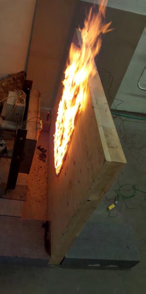
CLT panel behavior in medium-scale tests The test sample surface started to thermally degrade right from the start of the test. By ZACHAR et al. (2017), the combustion process and typical behavior of materials during thermal degradation is determined by initiation energy which is necessary for the material to ignite. The thermal degradation was accompanied by the color change of the surface and by production of the smoke. The surface area gradually grew (Fig. 2) and its color changed from brown to black. The flames on the surface appeared approximately in the 7th minute (Fig. 3). As stated by VAVRUŠKOVÁ and LOKAJ (2009), the wooden objects exposed to fire and temperature of about 300°C flame up on the surface and burn quite intensely at the beginning. The vigorous flame combustion lasted for about three minutes, then its intensity decreased gradually. In the 12th minute, it showed as a non-flaming combustion. As stated by OSVALD and GAFF (2017), combustion is typical in two phases for most combustible materials - the first stage typical by flaming combustion of gaseous products and the second stage represented by non-flaming combustion of the residues of the materials rich in carbon.
Fig. 2 The test sample at the beginning of the medium-scale test. Fig. 3 The test sample in the seventh minute.
When observing the macroscopics changes at progressing stages of thermal degradation of wood under elevated temperatures in longer time it is possible to observe only the formation of the char layer (OSVALD 2015).
As mentioned earlier (FRANGI et al. 2008), behavior of CLT panel in conditions of fire is characterized by the behavior of individual layers of the CLT panel. The process of
charring of the first layer of the CLT panel and the rate of charring is similar to the behavior of massive timber sample, taking in account the local increased charring at bonding of the layers. This fact is also confirmed by FRANGI et al. (2008), the depth of charring of the CLT panel is identical as for the homogenous timber until the first layer is completely charred. As MARTINKA et al. (2016) state, charred layer on the test sample surface slows down heating of non-degraded surface which results in decreasing the thermal degradation rate, gaseous products release rate, and heat release rate. The char layer works as an insulation layer. VAVRUŠKOVÁ and LOKAJ (2009), BLASS (1995) mention that thermal conductivity is approximately one sixth of the thermal conductivity of non-degraded wood. It also slows down the further thermal degradation of remaining wood.
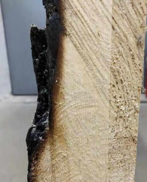
As mentioned earlier, in case of charring of a complete layer on the loaded side, two situations can occur: the char layer protects the residual cross-section against heat or the char layer can fall off. During thermal loading of the sample, the second situation appeared. The charred layer fell off in 37th minute. In this time the outer layer of the CLT sample was completely charred in the whole thickness at some places. We suppose the fall-off of this layer was caused by two effects – the pressure between the layers of the CLT panel and structure of the char layer. Approximately after 23rd minute, the temperature between the inner layer of the CLT panel and the outer layer on the exposed side ranged over 100°C. In the temperature span between 20°C and 150°C dehydration of wood starts, according to KAČÍKOVEJ et al. (2011), when wood loses water starting with free water and ending with bound water. A part of this water is cumulated between the individual layers of a CLT panel, therefore the pressure is formed at the mentioned contact. At the same time, heating of the PUR adhesive film releases and cumulates volatile products.
Charring of the inner layer started after fall-off of the outer layer of the panel. Fig. 5 shows charring of the inner layer especially at the places where outer layer has fallen off. The authors KLIPPEL et al. (2014) state that charring rate of the next layer of a CLT panel is twice as fast.
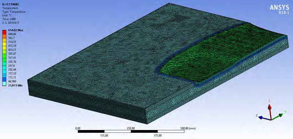
ZOUFAL et al. (2009) define the depth of charring as the distance between the outer surface of the intact timber and the position of the charring line. At the place where the falloff of the first layer appeared, the depth of charring was 28 mm (maximal value). At the places where the char insulation did not protect the remaining wood, the thermal degradation of the inner layer occurred. Simulation results Simulation result is illustration of charring ratio of CLT panel in 40 minute time span. Figure 6 shows a detail of the left half of the simulated panel without the char layer which has been removed. The color fields divide the CLT panel into the following layers: green color shows the char layer and border of charring, dark blue and dark green color depict the pyrolysis layer and light blue shows intact wood.
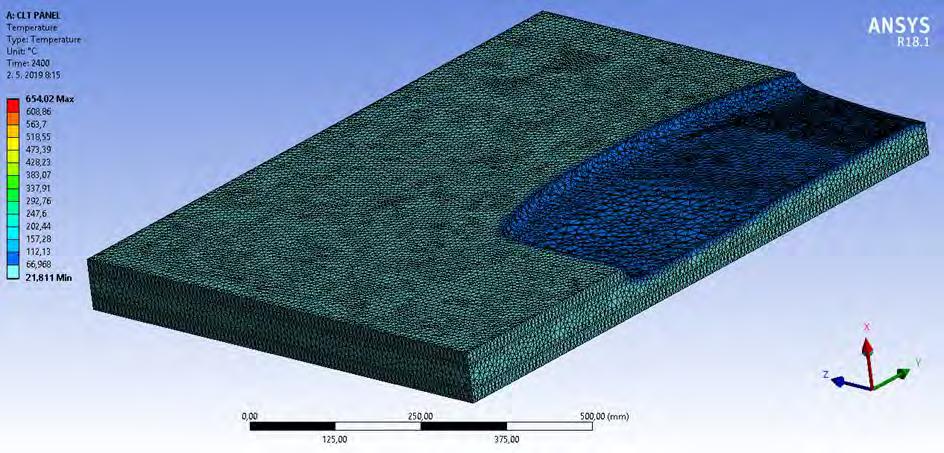
Maximal depth of the char layer in direction of the xaxis in the area of radiation panel achieved 15 mm, on the upper edge of CLT panel it achieved 19 mm. The program determined the average depth only on the bases of the thermally loaded area of the CLT panel after 40 minutes of thermal loading. The value of the average depth of charring was 9 mm. Based on the data on charring depth, the conclusion that charring of wood appeared only on the exposed layer of the CLT panel was reached, i.e. the first layer of the CLT panel exposed to thermal loading charred. The maximal depth of the pyrolysis in the direction of the x axis achieved 35 mm, on the upper edge it achieved 41mm (Fig.7).
According to the computer simulation, the flames appeared in 9th minute (Fig.8), having achieved the ignition temperature of spruce wood. The flame spread by linearvelocity across the surface until it reached the upper edge of the panel. Maximal measured
temperature on the surface on the exposed panel was 648°C. On the non-exposed side of the panel, the temperature did not increase.

Fig. 2 Char layer fall-off during the medium-scale test. Fig. 3 Cross-section of the sample after the medium-scale test.
Fig. 4 Charring after 40 minutes.
Fig. 5Pyrolysis layer.
800
700
Temperature
600
500
400
300
200
100
0
0 80 160 240
320 400 480 560 640 720 800 880 960 1 040 1 120 1 200 1 280 1 360 1 440
1 520 1 600 1 680 1 760 1 840 1 920 2 000
2 080 2 160 2 240 2 320 2 400
Time Maximum top slab temperature (medium-scale test) Maximum connection middle - top slab temperature (simulation) Maximum connection bottom - middle slab temperature (simulation) Maximum bottom slab temperature (simulation) Maximum top slab temperature (simulation)
Fig. 6 Thermal load.
The area of non-degraded wood in the cross-section has a significant impact on the value of its fire resistance since the wood under thermal degradation loses its mechanical and thermal insulation properties.
Evaluation of the char layer and the charring rate was also dealt by MENIS (2012). This author points out the fact that if the individual layers of the CLT panel are glued by PUR adhesive when exposed to fire effects the fall-off the char layer does occur. This phenomenon was observed on the samples when there was used five different PUR adhesives. MENIS (2012) also explains that fall-off the char layer did not appear when the bond between two layers was provided by MUF adhesive.
CLT panel performance in fire was also investigated by FRANGI et al. (2009). A small horizontal furnace was used to perform a fire test. The test was conducted the samples where different adhesives were used. The charring rate for the sample with MUF adhesive was constant. After charring of the first layer of the CLT panel, it did not fall off and protected the remaining wood against elevated temperatures.
During the test samples with PUR adhesive, the charring rate was not constant. Once the first layer has charred, it fell off. This fact led towards an increase in charring rate compared with charring of a homogenous wooden panel. Three other test samples in thicknesses of 60 mm which had a 20 mm thick layer on the exposed side were evaluated. The 28 mm thick charring occurred at 41st minute, 42nd minute and 44th minute.
FRIQUIN et al. (2010) dealt with the charring rate and charring depth of a CLT panel. They investigated the dependence on the fire scenario which affected the samples. The CLT panel was exposed to thermal loading equaling to Standard curve, Parametric curve and a Swedish curve of fire. At the same time, the changes in charring depending on the fire stage were observed. The char depth and charring rate were interpreted graphically. The results regarding charring are as follows FRIQUIN et al. (2010):
- When the test samples were exposed to thermal loading corresponding to the parametric fire curve, 20 mm char depth in case of 120thick test sample (the first layer thickness 19.5 mm) appeared in the 22nd minute. 20 mm charring depth in case of 240 mm thick test sample appeared in 29thminute. - When the test samples were exposed to thermal loading corresponding to the standard fire curve, 20 mm char depth in case of 180 mm thick test sample (32 mm thickness of the first layer) appeared in approximately in 43rd minute. 20 mm charring depth in case of 240 mm thick test sample (31.5 mm thickness of the first layer) appeared in 45th minute. - When the test samples were exposed to thermal loading corresponding to Swedish curve, 10 mm char depth in case of 240 mm thick test sample (29.5 mm thickness of the first layer) appeared in approximately in 20th minute.
The test samples exposed to thermal loading by a standard fire curve were tested for 150 minutes and longer. In that case, the charring depth of 28 mm appeared approximately in 48th minute on the 240 mm thick sample. In case of a parametric fire, charring was recorded approximately before 30th minute FRIQUIN et al. (2010): In case of Swedish fire curve, the recorded char depth appeared approximately before 20th minute FRIQUIN et al. (2010).
The fire performance of CLT panel was also dealt by KLIPPEL and FRANGI (2016). They summarised the other authors´results which focused on the influence of the adhesive on falling off the charred layer. There, CLT panel behavior in a fire was compared subjected to the use of PUR, MUF and PRF adhesive to glue individual layers. Based on the conducted research they came to the conclusion that in case of PUR adhesive use falling off the charred layer occurs in most tests. While, when MUF or PRF adhesive is used, the charred layer does not fall off.
CONSLUSIONS
On a CLT panel surface, a char layer is formed when it is thermally loaded in the same manner as on all wood-based materials. The process of charring depends on the fire behavior of individual layers of the CLT panel.
The results of the medium-scale test and the simulation by Ansys 18.1 program can be resumed into the following points: Maximal temperature on the exposed side of the panel in the medium-scale test was 711°C, maximal temperature on the exposed side of the panel in the simulation was 648°C. The flame on the surface of the sample appeared in 7th minute in the mediumscale test, the flame on the surface of the panel appeared in the 9th minute, In simulation, the formation of a char layer on the edge of the test sample was predicted. Due to the thermal degradation at this place, rounding appeared. In case of medium-sale test, there was no charring on the edge, so there was no rounding on the edge. In simulation, the charring of the first layer of the CLT panel was incomplete, therefore, it did not fall off. Even if the complete charring did appear, it is uncertain if the program would consider its falling off. The reason is that the kind of adhesive does not have such a significant impact in the simulation. In the medium-scale test, a complete charring of the first layer appeared. In the place where the charred mass fell off, the charring of the inner layer appeared.
As can be noticed, the simulation results and the medium-scale results are partially different. In case of the medium-scale test, the char layer was formed especially in the place radiation panel exposure. In simulation, the char layer was formed in the center (the place of radiation panel exposure) up to the edge of the test sample.
Ansys 18.1 program does not allow us to imitate the wood structure in detail including its defects. This fact might be the reason of different temperature development recorded on the exposed side. Meanwhile, in this type of simulation, it is not possible to imitate the falloff of the char layer, which appeared in the medium-scale test. This phenomenon bears a significant impact. If the char layer does not fall off, it protects by insulation the remaining wood mass and thermal degradation progresses more slowly. If the char layer falls off, the charring of the inner layer occurs. The charring rate proceeds twice as fast at the beginning. The increased charring rate was also mentioned by FRANGI et al. 2008 as the consequence of pre-heating of the timber in the layer.
The differences in the results are caused by the temperature of charring. It is necessary to put in the temperature of charring in Ansys 18.1 program. The temperature of charring was determined as 300°C according to STN 1995-1-2 (2008). However, KAČÍKOVÁ et al. (2001) state that charring of wood can appear at as low as 250°C.In the medium-scale test, the temperature of charring lower than 300°C imposed the differences in the depth of charring. The simulation program generates the simulation according to the input temperature of charring. The standard states the temperature of charring as 300°C for wood, in general; however, the individual species might have different temperatures of charring, which was not considered by the program. The charring temperature by the wood species has been specified only if in particular studies and as so it is not included in the standard. The amendment of the standard for the temperature of charring by wood species would need to be considered as it would produce the more accurate results in further investigation.
The main contribution of the research is the finding that the results of medium-scale tests of wooden construction members and the results achieved by the computational simulation are different, yet only to a certain extent. Medium-scale testing is, therefore, more suitable to state real fire behavior parameters for construction members and computational simulation is suitable for designing and dimensioning construction members and for predicting the behavior under thermal loading.
REFERENCES
ANSYS Inc. 2013. ANSYS Mechanical APDL Thermal AnalysisGuide. BLASS, H. J. 1995. Timber engineering: STEP 1: Basis of design, material properties, structural components and joints. Almere : Centrum Hout, 1995. 300 s. FONSECA, E.M.M., BARREIRA, L.M.S. 2009. Charring rate determination of wood pine profiles submitted to hidg temperatures. In Safety and security engineering III., 2009, s. 449457. FRAGIACOMO, M., MENIS, A., CLEMENTE, I., BOCHICCHIO, G., CECCOTTI, A. 2013. Fire resistance of cross-laminated timber panels loaded out-of-plane. In Journal of Structural Engineering, 2013, roč. 139, č. 12: :04013018. FRANGI, A., FONTANA, M., HUGI, E., JÖBSTL, R. 2009. Experimental analysis of cross-laminated timber panels in fire. In Fire Safety Journal, 2009, roč. 44, č. 8, s. 10781087. FRANGI,A.,FONTANA,M.,KNOBLOCH,M,BOCHICCHIO,G.2008. Fire behaviour of cross-laminated solid timber panels. In Fire Safety Science 9, 2008, s. 12791290. FRIQUIN, K. L., GRIMSBU, M., HOVDE, P. J.2010. Charring rates for cross-laminated timber panels exposed to standard and parametric fires. In World conference on timber engineering, 2010. KAČÍKOVÁ, D., NETOPILOVÁ, M., OSVALD, A. 2006. Drevo a jeho termická degradácia. Ostrava: SPBI, 2006. 79s. ISBN 80-86634-78-7.
KAČÍKOVÁ,D., KAČÍK,F.,HRNČIARIK,P. 2011. Vplyv teploty na chemické a mechanické vlastnosti dreva. In Delta, roč. 5, č. 10, s. 1620. KLIPPEL, M., LEYDER, C., FRANGI, A., FONTANA, M., LAM, F., CECCOTTI, A. 2014. Fire Tests on Loaded Cross-laminated Timber Wall and Floor Elements. In Fire Safety Science 11, 2014, s. 626639. KLIPPEL, M., FRANGI,A. 2016. Brandverhalten von Brettsperrholz. Ing Bautechnik, roč. 93, č. 8, str. 567-573. KUČERA, P., LOKAJ, A., KAČÍKOVÁ, D. 2012. Overenie spoľahlivosti prvkov drevenej konštrukcie vystavenej veľkorozmerovej požiarnej skúške. In Acta Facultatis Xylologiae Zvolen, 2012, roč. 54, č. 1, s. 95104. KUČEROVÁ, V., KAČÍK, F., SOLÁR, R., SIVÁK, J.2009. Porovnanie rôznych metód stanovenia celulózy po termickej degradácii smrekového dreva. In Acta Facultatis Xylologiae Zvolen, 2009, roč. 51, č. 1, s. 510. KUKLÍK, P. 2005. Dřevěné konstrukce. Praha : ČKAIT. 2005, 171 s, ISBN 80-86769-72-0. LEŠKO, R., LOPUŠNIAK, M.2015. Požiarna odolnosť drevených prvkov a konštrukcií viacpodlažnej budovy stanovené podľa Eurokodu 5. In Acta Facultatis Xylologiae Zvolen, 2015, roč. 57, č. 2, s. 135144. MARTINKA,J., KAČÍKOVÁ, D.,RANTUCH, P., BALOG,K. 2016. Investigation of the influence of spruce and oak wood heat treatment upon heat release rate and propensity for fire propagation in the flashover phase. In Acta Facultatis Xylologiae Zvolen, 2016, roč. 58, č. 1, s. 5-14. MENIS, A. 2012. Fire Resistance of Laminated Veneer Lumber (LVL) and Cross-laminated timber elements: Ph.D.thesis. Italy : Universitá degli studi di Cagliari, 2012, 221 s. ÖSTMAN, B., SCHMID, J., KLIPPEL, M., JUST, A., WERTHER, N., BRANDON, D. 2018. Fire design of CLT in Europe. In Wood and Fiber Science, 2018, špeciálne vydanie 50, s. 6882. OSVALD, A. 2011. Drevostavba ≠ požiar. Zvolen : Technická univerzita vo Zvolene, 2011, 336 s, ISBN 978-80-228-2220-6. OSVALD, A. 2015. Požiar odhaľuje slabé miesta drevostavieb. In Manažment rizík požiarov v prírodnom prostredí. Zborník vedeckých prác. Bratislava: Požiarnotechnický a expertízny ústav MV SR , 2015, s. 6273. OSVALD, A., GAFF, M. 2017. Effect od thermal modification on flameless combustion of spruce wood. In Wood Research, 2017, roč. 62, č. 4, s 565574. PAULĎURO M, KAČÍKOVÁ D. 2014. Vplyv charakteristík vybraných druhov drevín na úbytok hmotnosti v podmienkach simulujúcich požiar. In Delta, 2014, roč. 8, č. 16, s. 2427. Rozhodnutie komisie zo 7. augusta 2003, ktorým sa mení a dopĺňa rozhodnutie ro o ustanovení tried požiarnej odolnosti určitých stavebných výrobkov. STN EN 1995-1-2:2008, Eurokód 5: Navrhovanie drevených konštrukcií. Časť - 2: Všeobecné pravidlá. Navrhovanie konštrukcií na účinky požiaru. VAVRUŠKOVÁ K., LOKAJ A. 2009. Požární odolnost dřevěných konstrukcí. In Sborník vědeckých prácí Vysoké školy báňské – Technické univerzity Ostrava, 2009, s. 2530. ZACHAR, M., MAJLINGOVÁ, A., ŠISULÁK, S., BAKSA, J.2017. Comparison of the activation energy required for spontaneous ignition and flash point of the norway spruce wood and thermowood specimens. In Acta Facultatis Xylologiae Zvolen, 2017, čo. 59, č. 2., s. 79-90. ZOUFAL,R.,BAUMA,M.,KARPAŠ,J., 2009. Hodnoty požárni odolnosti stavebních konštrukcí podle Eurokódů. Praha : PAVUS, a.s., 2009. 126 s. ISBN 978-80-904481-0-0.
ACKNOWLEDGEMENT
This work was supported by the Slovak Research and Development Agency under the contract No. APVV-17-0005(70 %) and by the Cultural and Educational Grant Agenca of the Ministry of Education, Science, Research and Sport of the Slovak Republic on the basis of the project No. KEGA 009TUZV-4/2017 (30 %).
AUTHORS´ ADDRESSES
Ing. Katarína Dúbravská, PhD. Ing. Dominik Špilák Ing. Ľudmila Tereňová, PhD. Technical University in Zvolen Faculty of Wood Sciences and Technology Department of Fire Protection T. G. Masaryka 24 960 01 Zvolen Slovakia katarina.dubravska@tuzvo.sk xspilakd@is.tuzvo.sk ludmila.terenova@tuzvo.sk Mgr. Jaroslava Štefková, PhD. Technical University in Zvolen Institute of Foreign Languages 960 01 Zvolen Slovakia jaroslava.stefkova@tuzvo.sk
