nox
/xnu
ofile g/pr
chn ock.x Š st
IMPORTANCE OF IGBT DRIVERS Johannes Krapp, Product Manager, Driver Electronics
To ensure that power electronic components are reliably protected from the effects of non-permissible operating conditions, fast and reliable error detection and effective protective measures are essential.
I
n power modules, error management can be provided either by the system controller or by IGBT drivers. The system controller is suitable for reacting to slow failure modes such as overheating caused by excessive temperatures. Driver electronics, in contrast, are needed to detect and respond to sudden errors. Various driver concepts are available on the market today and differ as regards their applicability, efficiency and reliability. Fast errors in power converter systems include short circuits and circuit-induced overvoltages. Short circuits are the fastest errors. When power electronic systems are commissioned, connection and isolation errors are often the cause of short circuits, while in field applications short circuits may be due to faulty components. If a short circuit occurs in the load path or bridge branch, the collector current in the IGBT increases starkly, causing transistor desaturation. The IGBT modules available on the market today are short-circuit-proof for a brief time only. To prevent the IGBT from being destroyed by thermal loading, it is crucial that the short circuit be detected within this safe period and turned off reliably.
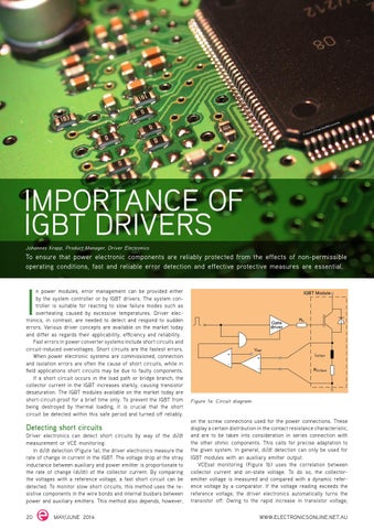
Detecting short circuits Driver electronics can detect short circuits by way of the di/dt measurement or VCE monitoring. In di/dt detection (Figure 1a), the driver electronics measure the rate of change in current in the IGBT. The voltage drop at the stray inductance between auxiliary and power emitter is proportionate to the rate of change (di/dt) of the collector current. By comparing the voltages with a reference voltage, a fast short circuit can be detected. To monitor slow short circuits, this method uses the resistive components in the wire bonds and internal busbars between power and auxiliary emitters. This method also depends, however,
20
MAY/JUNE 2014
Figure 1a: Circuit diagram.
on the screw connections used for the power connections. These display a certain distribution in the contact resistance characteristic, and are to be taken into consideration in series connection with the other ohmic components. This calls for precise adaptation to the given system. In general, di/dt detection can only be used for IGBT modules with an auxiliary emitter output. VCEsat monitoring (Figure 1b) uses the correlation between collector current and on-state voltage. To do so, the collectoremitter voltage is measured and compared with a dynamic reference voltage by a comparator. If the voltage reading exceeds the reference voltage, the driver electronics automatically turns the transistor off. Owing to the rapid increase in transistor voltage,
WWW.ELECTRONICSONLINE.NET.AU
