in.yj-2-ce control system Quick Start Card (European version)

Page 1

Quick Start Card

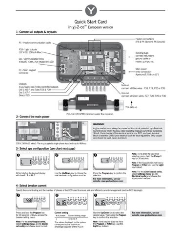
in.yj-2-ce™ European version 1- Connect all outputs & keypads Heater connections (P3 & P4 Element, P5 Ground)

P1 - Heater communication cable P33 - Light outputs (12 V DC, 500 mA Max.)

Bonding lugs: connect redundant ground cable to heater, pumps, etc.

CO - Communication links in.touch, in.stik, Aux keypad in.k120

Main power entry connection Aperture Ă˜ 2.54 cm (1'')

C1 - Main keypad connector

Outputs: in.yj-2 pack has 2 relay controlled outputs Out 1: K6-P and Tabs P23 & P39 Out 2: K7-P Direct: P25

Neutral: connect all Blue wires : P18, P19, P20 or P35 Ground: connect all Green wires: P27, P28, P29 or P30

This side up 75 L/min (20 GPM) minimum water flow required.

2- Connect the main power

WARNING! in.yj.ce models must always be connected to a circuit protected by a ResidualCurrent Device (RCD) having a rated operating residual-current not exceeding 30 mA. Correct wiring of the electrical service box, RCD, and pack terminal block is essential! Check your electrical code for local regulations. Only copper wire should be used, never aluminum. 230 V, 50 Hz (3 wires): The in.yj supports single phase input with up to 40Amp.

3- Select spa configuration (see chart next page) 1

2

3

Note: To re-enter the Low level selection menu, hold the Pump 1 key for 30 seconds. Note: If the keypad does not have a Program or Filter key, use the Light key instead.

At first startup the keypad display will show L 1 or LL 1.

Use the Up/Down key to choose the new low level configuration number.

Press the Program key to confirm the selection. For more information, see our website: www.geckoalliance.com

Note: For the Color keypad series, select Settings menu, go into Electrical config and choose the appropriate Low level.

4- Select breaker current Specify the current rating and the number of phases of the RCD used to ensure safe and efficient current management (and no RCD trippings).

1

2

3

98 Press and hold the Program key for 20 seconds until you access the breaker setting menu.

Current setting

Note: For the Color keypad series, select Settings menu, go into Electrical config and choose input current.

The values displayed by the system correspond to the maximum amperage capacity of the RCD.h

# of phases

Current setting range

1

10 to 40 A

Use the Up/Down key to select the desired value. Then press the Program key to confirm the selection. Note: If the keypad does not have the Program or Filter key, use the Light key instead.

For more information, see our website: www.geckoalliance.com


Configuration selection chart Software #312, rev. 001 Pump 2

Blower

Circ. Pump (CP) configuration

Ozone (O3) configuration*

Filter cycle daily

Heater pump

_

_

_

X (P23)

2 x 2 hours with P1

P1

_

_

_

X (K6-P)

2 x 2 hours with P1

_

2 x 2 hours with P1

Standard config. #

Pump 1

10

2SP (K7-P, K6-P) 8A-3A

11

1SP (K7-P) 4A

12

1SP (K7-P) 4A

13

1SP (K7-P) 8A

14

2SP (K7-P, K6-P) 8A-3A

20

2SP (K7-P, K6-P) 8A-3A

21

1SP (K7-P) 4A

22

1SP (K7-P) 4A

23

1SP (K7-P) 8A

24

2SP (K7-P, K6-P) 8A-3A

30

2SP (K7-P, K6-P) 8A-3A

31

1SP (K7-P) 4A

_

32

1SP (K7-P) 4A

1SP (K6-P) 8A

33

1SP (K7-P) 8A

34

2SP (K7-P, K6-P) 8A-3A

40

2SP (K7-P, K6-P) 8A-3A

41

1SP (K7-P) 4A

42

1SP (K7-P) 8A

43

1SP (K7-P) 8A

44

2SP (K7-P, K6-P) 8A-3A

_ _ _

_ _ 1SP (K6-P) 8A

X (K6-P) 4A _ _

_ _ _

_

_

_

_

_ X (K6-P) 1A Always On Direct (P25) 1A _ _ _ X (K6-P) 1A Always On Direct (P25) 1A

X (P23)

2 x 6 hours with CP

_

2 x purges

X (P23)

2 x 2 hours with P1

X (K6-P)

2 x 2 hours with P1

_

2 x 2 hours with P1

X (P23)

2 x 6 hours with CP

_

2 x purges with P1 2 x 2 hours with P1

_

X (K6-P)

2 x 2 hours with P1

_

_

_

2 x 2 hours with P1

_

_

X (K6-P) 1A

X (P23)

_

_

Always On Direct (P25) 1A

_

_

_

_ 1SP (K6-P) 8A

_

_

_ _

_

_

_

_

_

_ _ X (K6-P) 1A Always On Direct (P25) 1A

P1 6A (1,3KW) P1 6A (1,3KW) CP 6A (1,3KW) CP 6A (1,3KW)

X (P23)

_

6A (1,3KW)

_

2 x 6 hours with CP 2 x purges

P1 9A (2KW) P1 9A (2KW) P1 9A (2KW) CP 9A (2KW) CP 9A (2KW) P1 12A (3KW) P1 12A (3KW) P1 12A (3KW) CP 12A (3KW) CP 12A (3KW)

X (P23)

2 x 2 hours with P1

X (K6-P)

2 x 2 hours with P1

_

2 x 2 hours with P1

X (P23)

2 x 6 hours with CP

_

2 x purges

P1 16A (3,6KW) P1 16A (3,6KW) P1 16A (3,6KW) CP 16A (3,6KW) CP 16A (3,6KW)

* When the Ozonator is not controlled by a relay, it can be tied to Pump 1 Low speed or Circ. Pump. Pump using cable splitter AMP PN: 9920-401369.

Glossary X 1SP 2SP 4A, 8A-3A

Installed High speed only High and Low speed Output current: 1 speed or High-Low speed

For complete TechBook or more information, see our website: www.geckoalliance.com

© Groupe Gecko Alliance Inc., 2016 All trademarks or registered trademarks are the property of their respective owners.

9919-101445-B

Rev. 06-2016

www.geckoalliance.com


Turn static files into dynamic content formats.

Create a flipbook
Issuu converts static files into: digital portfolios, online yearbooks, online catalogs, digital photo albums and more. Sign up and create your flipbook.