13 minute read
Process Page: Wastewater Treatment Facility Basis of Design Fundamentals—Bartt Booz

Greetings from the FWEA Wastewater Process Committee! In October and November 2020, the Process Committee hosted a series of 10 virtual presentations under the theme, “Back to Wastewater Process Fundamentals.” Presenters covered a wide range of topics, ranging from process technology updates to supervisory control and data acquisition (SCADA) basics, design fundamentals, and lessons learned during construction. This article is a summary of the “Wastewater Treatment Facility Basis of Design Fundamentals” presentation that was hosted on Oct. 22, 2020.
Advertisement
Bartt Booz
What is a Basis of Design?
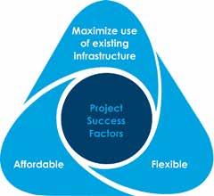
A basis of design (BOD) for a wastewater treatment facility project documents the principles, assumptions, rationale, criteria, calculations, and decisions made that impact the final design. The BOD typically follows a master plan or a facilities plan in the project development process and defines the goals of the project and project success factors. Projects that proceed without a well-defined project and detailed BOD can lead to costly changes during the final design phase.
Project Purpose
Understanding the project’s purpose is essential when developing the basis of design. Projects typically fall into one (or more) of four categories: S Rehabilitation and replacement S Permit compliance S Capacity expansion S Funding opportunities
Rehabilitation and Replacement
Many plants within the United States were built during the late 1970s and early ‘80s as a result of the Clean Water Act and the prevalence of grant money. Now over 40 years old, these plants may or may not have undergone at least one major upgrade during this period and may operate equipment that is well past its expected useful life.
Eventually, equipment and piping need to be replaced, concrete tanks need to be rehabilitated, and control and electrical systems become obsolete. Many projects are driven simply by rehabilitation and replacement, when the cost of maintaining the old equipment and systems becomes too high.
Permit Compliance
Plants may also require upgrades when new, more-stringent permit limits are issued by the regulatory agency. It’s always beneficial to try to achieve new limits using existing tankage or repurpose unused tanks whenever possible to reduce project costs. In addition, many of today’s innovative technologies use process intensification to achieve more in a smaller volume.
Capacity Expansion
When growth overtakes the available capacity of a plant and process intensification is maximized (or more expensive to implement), additional treatment volume or trains should be considered to meet future growth. Ideally, some foresight was established during the original plant design for its eventual expansion. If not, you may have to implement creative ways to add capacity within the available site footprint and hydraulic profile.
Funding Opportunities
Plant upgrades may also be performed sooner than required simply due to the availability of grant or low-interest loan funding. Future effluent limits may also be on the horizon, and conducting upgrade projects when grant funding is available is a prudent strategy. This often occurs with plants within a total maximum daily load (TMDL) area with an established basin management action plan (BMAP) where a schedule for compliance may be forthcoming.
Discharge Standards and Permit Limits
A BOD report should state the treatment plant’s current effluent limits and what should be achieved following the upgrade. Limits depend on the destination for the effluent and the location of the plant. A 100 percent reuse plant will have different effluent
limits than a plant that discharges to surface water, even if that discharge is only occasional.
A plant that falls within a priority focus area (PFA) of a BMAP will have different limits than one without a BMAP or impairment. Limits may also be in place for plants that do not meet the primary and secondary drinking water standards during annual sampling (carefully consider the analytical methods used, as the detection limits during sampling should not be higher than the standard).
Flows and Loads
A BOD report for a treatment plant upgrade will have an assessment of current and future flows and loads to the plant. Historic influent and effluent flow data are typically accessible, as shown in Figure 1. The plant’s daily monitoring reports (DMR) and the last capacity analysis report (CAR) are excellent sources of information. Each CAR is required to summarize the permitted and design capacities of the plant, as well as monthly average, three-month average, and annual average daily flows for the past 10 years or for the facility’s time in operation. Also required are flow projections based on local population growth and water usage rates for at least the next 10 years; an estimate of the time required for the three-month average daily flow to reach the permitted capacity; recommendations for expansions; and a detailed schedule showing the dates for planning, design, permitting, start of construction, and operation of the new or expanded facilities.
Future flows can be difficult to predict. During Florida’s 2007-2008 economic downturn, much of the state’s anticipated growth stalled, which deferred capacity expansions at many plants. Currently, approximately 1,000 people are moving to Florida each day, and some communities are experiencing historic growth. In some cases, as soon as a capacity upgrade is designed, planning for the next upgrade begins. While planning with certainty is impossible, intelligent future flow estimates that document the assumptions should be made and reevaluated periodically.
A BOD report should also summarize the current plant loadings using available data as a starting point. Effluent data are typically readily available, but a complete assessment of the influent loads to a plant, at least on a consistent basis, typically is not. Permits often do not require sampling for some of the influent loads that are beneficial in plant evaluations. Supplemental influent sampling data may need to be requested from the plant operations staff.
The amount and type of data needed is dependent on the purpose. Supplemental sampling can be expensive if sent to an outside laboratory, so a clear purpose for the data requested is essential. For example, if only a high-level alternatives analysis is being conducted using process modeling software, there may be sufficient data available to extrapolate what is needed to accomplish the modeling without supplemental sampling.
If a calibrated process model of the plant is needed to conduct an in-depth evaluation of process and operational alternatives, then supplemental influent sampling may be required to use actual versus extrapolated influent values. Creating a calibrated model involves adjusting parameters in the model to mimic a known outcome from the actual treatment plant data (typically a maximum month loading condition). Ideally, the model will output similar effluent quality and solids production rates as the actual maximum month condition.
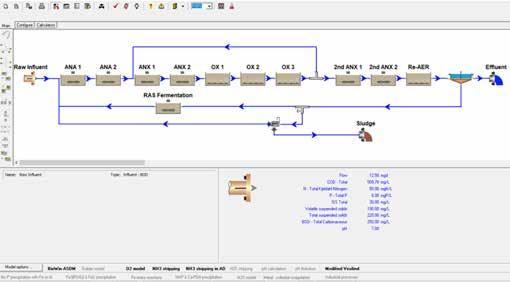
Figure 1. Example of influent and effluent data.
Evaluation of Existing Conditions
Evaluating existing conditions at a plant always begins with the existing design basis. What is the existing plant designed to achieve, what is the current process flow, and how much flexibility is there, either hydraulically or operationally? Assess the current tank sizes and equipment capacities to determine the potential to gain additional capacity through a rerating of the plant. Identify limitations in the process (or hydraulically) that may hinder your goals. Next, conduct a multidiscipline review of the unit processes impacted by the project to determine their needs. This can range from a structural review of the condition of the existing tankage to the age and condition of the electrical systems.
Code compliance must also be evaluated. Consider the National Fire Protection Association (NFPA) 820 standard, which provides electrical classification requirements for various wastewater collection, treatment systems, and solids handling systems. Every wastewater design professional should understand NFPA 820 and National Electrical Manufacturers Association (NEMA) requirements as they relate to improvements to an existing facility.
The BOD must also clearly identify the owner’s wastewater design standards. These may range from a simple list of acceptable manufacturers to complete specifications in the Construction Specifications Institute (CSI) format. Unwritten equipment preferences may also exist, and operations and maintenance staff may have a preferred process or equipment that requires duplication at other facilities. If sole-sourcing is needed, it’s important to follow all of the owner’s procurement requirements when creating project specifications.
The owner’s SCADA standards must also be understood during the basis of design. The SCADA architecture impacts the electrical, instrumentation, and control designs and must be identified in the BOD so that the design team can understand the controls architecture of the plant. Continued on page 30
As-Built and Record Drawing Information
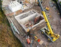
Discrepancies often occur between asbuilt information and actual field conditions. Inaccuracies in the record drawings can exist when engineers develop them from a contractor’s redline as-built drawings. To avoid conflicts or errors in the design, collect field measurements of visible areas whenever possible, especially in areas with conflict potential. For underground utilities, ground penetrating radar (GPR) may be beneficial to determine the horizontal locations of pipes and electrical duct banks in underground utilities. When the potential exists for vertical conflicts, consider subsurface utility exploration (SUE), using vacuum extraction to obtain vertical elevations and confirm pipe sizes. The strategic use of SUE can help to avoid conflicts and potentially large changes orders and schedule delays during construction.
Confirm the vertical datum of any record drawings you rely on for your design. Original plans might use National Geodetic Vertical Datum (NGVD) 29, while recent surveys of structures are typically in North American Vertical Datum (NAVD) 88. Conversion factors between the two exist, but you should survey the structures and pipes directly impacted rather than rely on old information.
For complex pump rooms or piping arrangements, 3D scanning may be used where as-built information is not accurate and where a Revit model of existing infrastructure must be created. Figure 2 is an example of a 3D scan of a below-grade pump room.
Hydraulic Evaluation
The importance of the hydraulic evaluation cannot be overstated, as an imbalance of flows (and loads) to each unit process can create plant performance issues throughout the life of the facility. Start by building a hydraulic model of the plant, or at least the unit processes, that are being impacted by the project. The model can consist of proprietary software or simply an Excel spreadsheet. Once the model is built, it’s beneficial to model a condition from a past set of record drawings or upgrades to see if the created model mimics the previous design.
Incorporate any plant recycle flows into the hydraulic model where they occur and talk with plant operators about their target recycle rates across various flow conditions. Check whether flow-splitting weirs or control weirs are submerged under any flow conditions. If submergence has occurred, assurance of acceptable flow split cannot be guaranteed.
Adding unit processes into an existing hydraulic profile is easier when there is a large drop in the profile. It’s more challenging when only a few inches are available, especially when flow splitting structures need to be incorporated. Consider computational fluid dynamics (CFD) modeling to confirm how a hydraulic control device is going to behave, particularly if you must develop a nonstandard arrangement to fit a structure within a tight hydraulic profile.
As previously noted, do not solely rely on record drawing elevations for the hydraulic evaluation, as the opportunity for error is too great. Obtain true survey information whenever possible. Another important practice is to take field measurements to confirm that the calculations are accurate. This entails physically going to the plant to take water surface measurements, while documenting the current influent and recycle flows. As you perform a walkthrough, collect measurements of depth to water surfaces from the tops of structures, depths over weirs, and at flow-splitting structures, and where flows enter a new unit process.
Based on those flows and measurements, conduct a model run at the flow rate and recycle rate observed at the plant to see if your field measurements match the theoretical model. If the theoretical aligns with the actual measurements, you should have greater confidence in the model. If they don't, then either the model is incorrect, or something else is happening in the field that is not readily apparent and requires additional investigation.
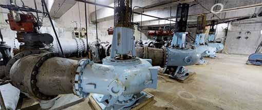
Figure 2. A 3D scan of below-grade pump room.
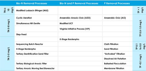
Table 1. Example of Screening-Level Evaluation
Alternatives Analysis
Once the basis of design has identified the drivers and needs for a plant upgrade, the next step is to identify the available alternatives that achieve the established goals. Begin by prescreening alternatives to create a short list
of options for further evaluation. The short list can then be taken through a more-detailed analysis to determine the recommended alternative. The owner and operations staff should be involved throughout this process. Important factors to consider include: S Lowest capital cost versus lowest operational cost. Determine the net present value over a 20-year planning period for each alternative. S Conventional versus innovative processes.
Does the owner prefer nonproprietary solutions, established technologies, or new technologies? Consider whether the design performance basis is coming from a consulting engineer or a technology provider. S For facilities where space is limited or reserved for future expansion, repurposing old tanks may be favored over technologies requiring new tanks.
Other evaluation criteria may include technologies that can be expanded easily or technologies that are robust and operatorfriendly versus those that require more monitoring and control.
Table 1 is an example of a screeninglevel evaluation for nitrogen and phosphorus removal processes to achieve varying effluent limits.
Identifying Solutions
Following the detailed evaluation, identify a proposed solution. Review the original project success factors and ensure that you have met the criteria established with the owner at the project’s inception. Success factors will differ for every project, but the solution should be a mutual effort among consultants, senior decision makers for the owner, and operations and maintenance staff. Success is more likely when collaboration occurs. Once you’ve established the process design basis for the recommended alternative, all other building disciplines (architectural, structural, mechanical, instrumentation, and electrical) should summarize their design criteria for every aspect of the future upgrade.
Summary
This high-level overview of some of the important elements of a basis of design for a wastewater treatment facility upgrade has hopefully given you a few strategies to implement during your next project.
To summarize: S The basis of design serves as a roadmap to a successful project and mitigates complications or rework during final design. S Assess the current and future flows and loads and use existing data sources and supplemental sampling to develop a complete picture. S Understand current and future discharge limits and what may be driving those limits. S Properly assess existing conditions.
Do not trust the as-built drawings.
Instead, take the time to confirm existing conditions to ensure that your design can properly incorporate within the existing facility. S Understand the plant’s hydraulics and confirm that your calculations are representative of the existing conditions. S Identify feasible alternatives and prescreen the alternatives for more detailed analysis. S Develop the recommended alternative with input from the owner. S After developing the recommended alternative, review your project success factors identified at the start of the project to ensure that you hit the target.
Bartt Booz, P.E., is senior project manager at Wright-Pierce in Maitland. S