29 minute read
Alfredo Portone

THE ITER MAGNET SYSTEMS
Alfredo Portone (Fusion for Energy)
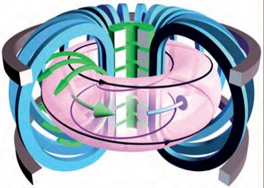
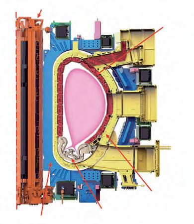
Fig. 1. The toroidal field (TF) magnet system is made by the array of D-shaped (blue) planar coils, producing the toroidal magnetic field component (black circulating arrows). The Poloidal Field (PF) magnet system is made by the Central Solenoid (CS) coils (green) and Poloidal Field (PF) coils (grey), which are solenoids of different radii and shapes that generate the poloidal magnetic field component (green circulating arrows). The combination of this two field components, together with the field generated by the plasma current itself (inside the pinkish volume) creates the confinement field caging the charged ions and electrons up to thermo-nuclear temperatures. Magnets are at the core of any tokamak design and operation. Indeed, the Russian acronym tokamak Toroidalnaya Kamera i Magnitnaya Katushka (Toroidal Chamber and Magnetic Coil) transmits this message very clearly. As such, the design and features of magnet systems have far-reaching implications in terms of performance, operation and cost of any reactor of this type. Before offering an overall description, it is important to mention that magnets in tokamaks are not only used to generate the toroidal magnetic cage needed to confine thermo-nuclear plasmas. In fact, they are deployed to carry out several other key functions such as driving the plasma current, controlling the position and shape of the plasma column, suppressing or enhancing transport at the plasma edge, correcting error fields etc. Tokamak magnet systems can be divided in two main classes based on the type of field component they generate, i.e. the toroidal field (TF) magnet system and poloidal field (PF) magnet system (Figure 1). A third class, less challenging in terms of design and operation, is made by the field correction magnets (not described in this chapter). The functions and requirements of TF and PF systems are almost complementary and, they differ profoundly in terms of design features. However, they do share one common characteristic: they must be superconducting.
THE NEED FOR SUPERCONDUCTIVITY
Next-generation tokamak reactors will have to produce energy at as low as possible cost. Since the kWh cost is driven primarily by the capital cost of the plant, in turn, is driven by machine size, it follows that, for the same energy output, compact tokamaks have a clear advantage over larger reactors. Assuming that the plasma power output for a given plasma volume and shape is driven by the external toroidal field through the B4-scaling (see below), future reactors will naturally need to be compact and capable of producing as strong a magnetic (toroidal) field as possible. The technology maturity and industrial know-how reached in the construction of low temperature superconductors (LTS) offer an unprecedented opportunity to meet these requirements by building high field, superconducting magnets. A simple example may help to elucidate this point. Let us consider a thermo-nuclear plasma generating a fusion
power PFUS with a steady state toroidal field B obtained by passing a current density J through a magnet volume VTF×In ITER, PFUS≈ 500MW, B≈ 5.2T, J≈ 10A/mm2 and VTF≈ 500m3. If resistive (copper) magnets at room temperature are used, a Joule power density hJ2≈ 2MW/m3 i.e. 1GW needs to be constantly removed from the magnet winding, i.e. twice the power generated by fusion is dissipated in the form of Joule heating in the resistive magnets. Clearly, if a resistive tokamak design route is to be followed, we need to drastically reduce the current density J and, accordingly, the size of confinement field B. So, to maintain the same reactor performances the reactor size will have to be increased at the expense of an increase in overall capital cost. This is not currently the preferred route and the clear trend in tokamak research is towards compact, high field, superconducting magnet reactors.
THE CONDUCTOR AS MAGNET SYSTEM CORNERSTONE
Both superconducting and normal conducting magnet systems all rely on the performance of their basic building block, the conductor. The performance of a magnet system as a whole is dictated de facto by the capability of each of its electrical turns (i.e. conductors) to carry the design current in stable mechanical, electrical and thermal conditions.
By focusing on superconducting magnet systems for nuclear fusion reactors, an initial feature stands out with respect to other design environments such as those concerning medical (NMRs) or accelerators (HEP) applications: the need to remove a large amount of power steadily and reliably from the conductor volume. i This fundamental aspect of a superconducting magnet for fusion application has led the design community to turn its attention to a specific conductor design concept for all type of magnets involved in this application, i.e. the Cable In Conduit Conductor (CICC). This type of conductor relies on the forced flow of supercritical helium through the intricate bundle of wires making up the superconducting cable, which in turn is contained inside a metallic conduit (jacket), typically made of austenitic steel, titanium or another high performing structural material. Some typical examples of these conductors for ITER are shown in Figure 2 below.
i Indeed, in HEP or NMR magnets the heat to be removed is negligible since they operate in steady state and without significant power deposition from external radiation sources.
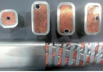
Fig. 2. An overview of Cable In Conduit Conductors (CICCs) used in fusion application. In the top left picture, a typical PF magnet CICC used in ITER, showing the thick circle-in-square steel conduit containing the circular superconducting cable made by a bundle of copper and superconducting, chromium coated wires. The image shows the six petal sub-stages encircling the central channel needed to lower the quench pressure in the CICC caused by the large hydraulic impedance of the long double pancakes. In the top right picture, a TF CICC with the typical circular conduit and exploded view of its components: the central spiral, the six petals and their steel wraps aiming to protect the cable during its insertion in the jacket. In the bottom left picture, the same TF CICC is shown in cross-sectional view, zooming in on its key elements, i.e. a superconducting wire made, in turn, by thousands of Nb3Sn superconducting filaments. Bottom right: a set of CICCs based on cables of different aspect ratios with relief channels jacketed in a steel conduit.
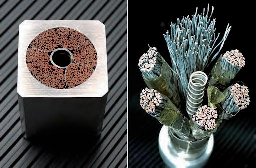
Void fraction for forced He circulation
Pressure relief channel
Strand
1,000 + 5,000 filaments
Steel jacket
Strand bundle
The CICC concept is based on a fundamental property of supercritical helium: its heat capacity per unit volume in the temperature range (4.5 K-6.5 K) relevant for Low Temperature Superconductors (LTS) operation is exceptionally high compared to other materials, including metals. Thus, a force flow of helium in direct contact with cable wires provides good heat removal (high wetted perimeters, good convection from surface to fluid) as well as excellent cable thermal stability due to the large buffer of heat that the supercritical helium can absorb without a large temperature increase at that range. These heat removal and stability features are priceless assets in the design of magnets that must operate in presence of the large thermal loads typical of fusion reactors.
A downside of CICC operating at high magnetic fields (e.g. > 6T) affecting strain-sensitive superconducting wires (such as Nb3Sn) is the compressive stress that, in the most commonly-deployed manufacturing route wind-andreact, the conduit (jacket) transfers to the cable due to its different thermal contraction. For the ITER most prominent example, the TF conductor, a cable made of about 1,000 wires is manufactured by twisting together in different stages and pitch length Nb3Sn and copper strands. Cables produced in lengths of up to 750 m are inserted into a steel pipe (jacket) of circular cross section, about 2 mm thick, which is then rolled down to meet the specified cable void fraction. Then the CICC produced are wound in the final shape in units called double pancakes (see Figure 3). All these processes (i.e. cabling, cable insertion and compaction, CICC winding) are carried out at room temperature. At this point the double pancakes are heat treated for about 20 days up to 650 °C to allow diffusion of Nb and Sn, thus producing the A15 superconducting composite. During this phase (reaction heat treatment, RHT) the superconducting material forming the cable wires goes through phase changes. During the cool-down from 650 °C to room temperature (and further, after cool-down to operating temperature) the steel conduit contracts more than the Nb3Sn wires and the cable ends up in a compressive state of stress and strain, which reduces the current carrying capability of the cable itself. To summarise, due to the differential thermal contraction between the
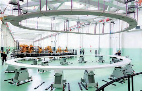
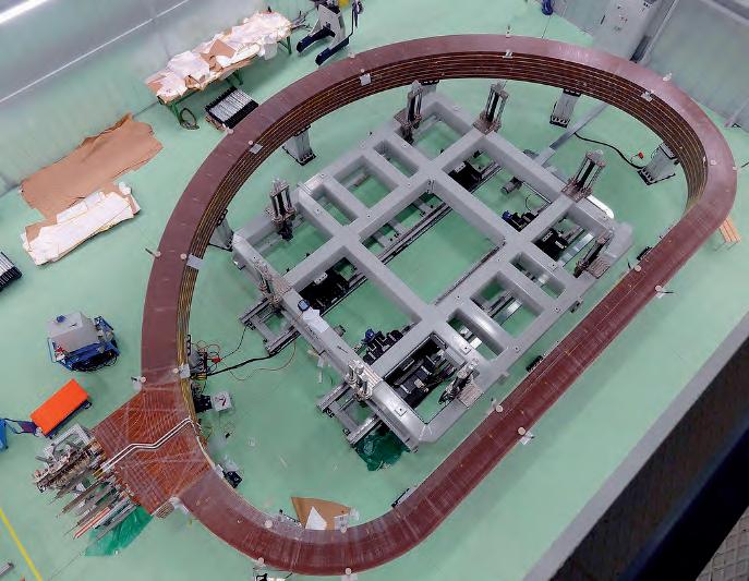
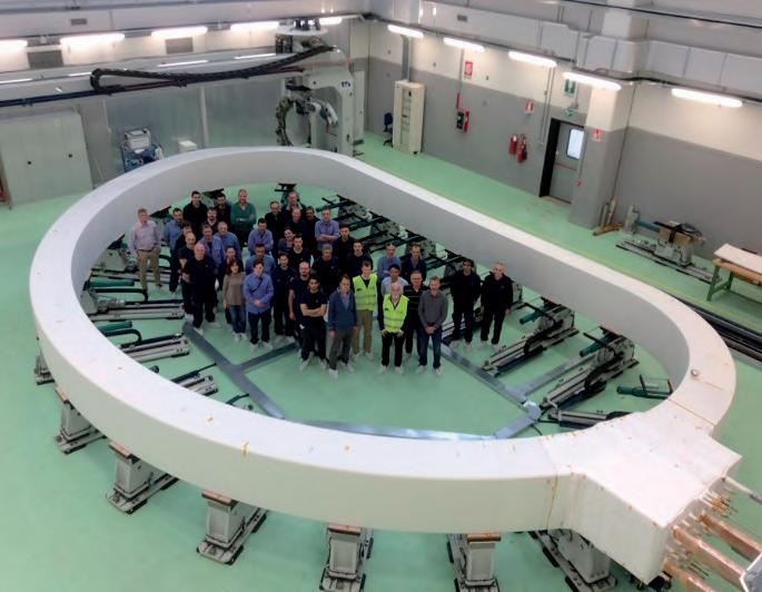
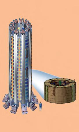
Fig. 3. A TF double pancake (DP) is wound in D-shape (top left). Seven of these DPs are then stacked together (top right) making up a winding pack (bottom left) of an ITER TF coil. All together, the seven DPs have 134 turns, each carrying 68 kA. The first winding pack was produced by ASG in Europe (bottom right).
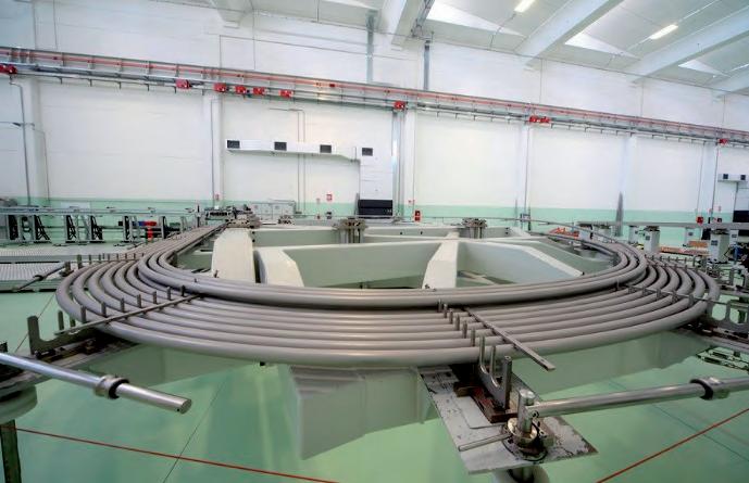
cable and the conduit, the CIC conductor suffers a considerable reduction (typically a factor up to 2) in its full potential current carrying capability at operating temperature. This down side of CICC has been known since the beginning they started to be used in the design in high field, LTS magnets in fusion. A common workaround is to size the cable with sufficient Nb3Sn wires to ensure that, despite the loss of current carrying capacity, there is sufficient margin to overcome the detrimental effects of jacket compression. Another approach, used in the KSTAR for example, is to deploy conduits whose material best matches the thermal contraction of Nb3Sn wires (in particular, the INCOLOY alloy).ii A further alternative is to develop superconducting materials which are less strain-sensitive that Nb3Sn (NbAl is a good example). More worrisome, however, is something that only emerged since the tests performed in the Central Solenoid Model Coil (CSMC) in the 2,000s, is the observed permanent loss of current carrying capability due to conductor degradation, originating from the fracture of the Nb3Sn filaments embedded in the superconducting wires as a result of the cyclic application of thermal or electromagnetic loads. This problem was eventually solved by stiffening the Nb3Sn cables via a reduction of the twist pitches and void fraction used in the different cabling stages. A completely different route to solve the loss of current carrying capacity of Nb3Sn cables is to adopt a react-and-wind route to magnet manufacturing. This approach holds high potential but still lacks full industrial practice and validation. Indeed, if the Nb3Sn cable is jacketed after it undergoes RHT and it is brought to RT in a stress-free state, the compression by the (steel) jacket is substantially reduced in operation at 4.5K. The difficulty to overcome is to validate a winding process that grants cable integrity during winding once the fragile A15 composite is formed. Because the strain is inversely proportional to the bending radius, this is very difficult to apply to compact tokamaks. In ITER, as mentioned, the CICCs used to wind the Toroidal Field (TF), Central Solenoid (CS) and Poloidal Field (PF) coils are sized to have enough
ii The use of Incoloy as jacket material has to be carefully considered in light of the risk of occurrence of the so-called Stress Accelerated Grain Boundary Oxidation (SAGBO) phenomenon leading to major cracks in the material if the alloy is exposed even to a few ppm of oxygen during the conductor RHT process.
iii It is worth recalling the critical current density in
LTS is a function of local temperature, magnetic field and, in Nb3Sn wires, also of the longitudinal filament strain. superconducting cross-sectional area to flow, at the reference temperature, field and strain conditions, the nominal current. As an example, the cross-sectional area occupied by the superconducting wires in the ITER TF CICC (Figure 2) is about 40% of the overall cable space area. About 30% of the cable space is used to flow the supercritical helium coolant and about 25% of the cable space is occupied by high conductivity copper wires. Such copper wires function in the CICC is to transiently carry the cable current during a loss of superconducting state by the superconducting CICC wires, thus providing the key protection function to the CICC in case of magnet quench. By this term, in fact, we refer to a loss of superconducting state by the LTS wires as due, for example, to some local temperature increase (e.g. due to the heat generated by the mechanical friction of some wires) which make some wires to exceed, locally, the critical current density.iii As such, the no-longer superconducting wire start to dissipate energy by Joule heating as any normal conducting wire, leading to a further increase of the local temperature that propagates along the cable and heats-up the helium in contact with the wires. Both phenomena (i.e. temperature conduction along the cable and, in particular, helium heating and consequent expansion) contribute to the rapid spread of the normal zone to large lengths of the magnet winding. As LTS wires are poor normal conducing material once they switch back from a superconducting to a normal conducting state, the copper in the CICC provides better electrical conductance and lower Joule energy dissipation for the same cable current to be carried. As all type of wires (i.e. LTS and copper) are in electrical contact inside the CICC, the current will gradually transfer from the normal conducting LTS wires to the better conducting copper wires. As this chain of events starts to unfold, a resistive voltage starts to appear along the cable and, by instrumenting the magnets, it can be picked-up by properly located voltage taps and their voltage signal used to trigger a protection discharge of the whole magnets affected. By adequately sizing the copper cross section in the CICC (i.e. number and diameter of the CICC copper wires) and the external discharge resistor in which the magnet current is dumped and dissipated, it is possible to limit the hot spot temperature of the quenched cable below damaging values (typically, < 150 K).
Beside the threat of large temperature excursions capable of potentially damaging large section of superconducting magnet winding, another danger associated to magnet quenches is due to the pressure increase associated to the expanding helium once it is heated-up. For this reason, 5% of the ITER cable space is used by a central cooling channel whose purpose is to lower the helium flow pressure drop in operation as well as to mitigate the CICC quench overpressure that might occur due to the large hydraulic lengths of the ITER coils windings. Essentially, such central channel acts like a vein bypass. As a last step in the CICC design, and only after the design of its superconducting cable, the cross-sectional area of the conduit (jacket) must be determined. As shown in Figure 2, the conduit cross section can come in various shapes and sizes. For example, the CS and PF conductors of ITER feature a circle-in-square conduit made of high strength steel alloys obtained by hot extrusion of square bars. Alternatively, the CICC cable can be rectangular in shape and the jacket simply obtained by plastically deforming it after cable insertion a circular pipe of appropriate thickness. A distinctive feature of CICC versus, for example, normal conducting magnets, is the complete segregation they introduce between the current carrying and load carrying function. In other words, CICC cables carry the current whereas CICC conduit bears the loads. On this basis, the design of the CICC conduit is the result of an iterative process of global and local stress analyses (see below) in which the previously-designed superconducting cable adds very little stiffness to the magnet and, from a mechanical standpoint, it can be neglected. In conclusion, CICCs are, as has been said, the cornerstone of fusion superconducting magnets. For several decades, their design has been supported by a broad range of test campaigns aimed at verifying, their critical parameters such as current sharing temperature, AC losses, hydraulic friction factors, etc. using representative short samples. A large amount of data and confidence has been gained through these tests campaigns, which are now a key element in the validation of any CICC design. Given the criticality of their performances and the complexity of the assessments involved, conductor modelling, testing and assessments remain a very active area of research striving for continuous improvements.
THE TOROIDAL FIELD COILS MAGNET SYSTEM
The toroidal field is the main magnetic field component at the basis of the tokamak confinement concept. Indeed, the closed field lines along which the charged particles guiding centres move freely while confined are predominantly toroidal. Differently from other topologically similar devices (e.g. Reverse Field Pinches) tokamaks toroidal fields can be up to ten times larger than the poloidal magnetic field component, which is obtained by the super-position of the plasma self-generated field with the field generated by the poloidal field magnet system (see Figure 1). Beside confinement, tokamak toroidal fields also play a key role in stabilising the main MHD modes that would otherwise drive the plasma column unstable (Section 3.1). In essence, the main features of tokamak toroidal field are steady state, high intensity magnetic fields. The toroidal field magnet system consists of an array of N identical planar, typically D-shaped coils symmetrically spaced around the machine vertical axis (Figure 1). The same current I flows in each conductor (CICC) of each one of these magnets and it determines the toroidal field strength B0 on the plasma axis with major radius R0 using the simple formula B0 = m0NI/(2pR0), where m0 = 4p × 10–7 H/m is the permeability of vacuum (see Section 3.1). In ITER, each one of the 18TF magnets are wound with 134 turns, each carrying 68kA and producing an overall toroidal field B0 = 5.3T on the plasma axis located at R0 = 6.2m. One of such magnet after completion is shown in Figure 3. Each TF coil magnet weights about 300 tonnes and the magnetic stored energy in the TF magnet system once energised at full current is about 41 GJ. Due to the 1/R dependence of the toroidal field, it follows that at small radii the toroidal field increases in intensity, leading to large Lorentz forces per unit length f ≈ IB/2 in the innermost sections of its magnets. For example, in ITER TF inner side the magnetic field reaches up to 11.8 T. Such 1/R dependence is exploited in the design of D-shape (bending free) coils whose local curvature 1/k is proportional to field intensity or, alternatively, whose radius of curvature k is proportional to R, i.e. k = cR. By doing so, the coils
Fig. 4. The ITER TF winding pack and coil case cross sections at the equatorial inner and outer position.

are under a pure tension T along their whole perimeter, thus minimising the in-section bending stresses and, therefore, the structural material in its resistant section. In fact, it turns out that the constant tension is obtained by the simple formula T = (m0/4p)NI2log(Re/Ri)1/2, where Re and Ri are the maximum and minimum coil radii. Bending free coils have a variety of mathematical properties vis-à-vis their perimeter length, radial build, inductance, etc., and, although their shape does not need to be strictly followed in ‘real life’ magnets, they provide useful guidance to the magnet designer.In addition to the constant, or nearly constant, tension T (sometimes referred to as in-plane bursting force) toroidal magnets experience also another magnetic force, the so-called in-plane centring force. This force results from the interaction of each coil with the surrounding N-1 toroidal magnets and it needs to be precisely reacted to keep the correct assembly configuration of the magnet system in operation. Two different types of structures react such centring forces, namely bucked or wedged structures. In the former (e.g. used at JET the toroidal field magnets push directly against a central column acting as a cylinder under external pressure located inside the toroidal field coils. Alternatively, each coil is in direct contact with the two neighbouring ones pushing against them in a wedged configuration, so forming a 360 degrees vault. In ITER the preferred solution is to use a wedged structure so avoiding the central solenoid joints and helium inlets to find themselves on the main load path of the toroidal field coils. In this way, a clearance gap grants mechanical de-coupling between the central solenoid and the toroidal field magnets inner vault.Such in-plane Lorentz forces (tension and centring) acting on each toroidal field magnet are due to its interaction with the toroidal field generated by the ensemble of N toroidal coils. As such it scales with the square of the coil current I2 and linearly with the number of coils N, the typical figure of merit for each coil force being given by (m0/4p)NI2. In JET such factor is 5MN, in ITER is 150MN, while in DEMO it is expected to be about 370MN! These huge TF tension and centring forces are static load that must be carried by high strength structural materials such as austenitic steels, mostly obtained from large, forged structures (as we have already seen, the CICC cables are not designed to carry any mechanical load). The centring forces are reacted by the
steel cases inside which the CICC are wound in D-shaped winding packs (see Figure 3). On the other hand, the tension (bursting) forces are reacted by both the steel cases as well as the CICC conduit as discussed above. An ITER TF meridian cross section is shown in Figure 4, together with the TF steel case used to insert the winding pack shown in Figure 3. Beside the in-plane forces above, the interaction of the current flowing in each toroidal magnet with the poloidal field generated by the plasma and poloidal field coils result in another component of force, now perpendicular to the plane of the coil and, as such, called out-of-plane force. Intuitively this force scales, again, with the coil current I multiplied by the strength of the poloidal field that in turn is proportional to the plasma current IP (see next section). Out-of-plane forces break the ideal bending free equilibrium that in-plane forces and D-shape coils would otherwise enjoy. As a result, they lead to an overall overturning (radial) moment MR that roughly scales as MR≈ (m0IPIH/4)θ(IPF/IP), where H is the height of the toroidal coil and θ(IPF /IP) is an a-dimensional function of the poloidal currents normalised to the plasma currents IP. In ITER MR varies during operation scenarios in the range MR = 50 ÷ 250MNm. Such large forces and moments are reacted by connecting all the coils to each other using the so-called inter-coil structures that link each coil to the neighbouring ones at a different location along the coil perimeter. This increases the overall torsional stiffness of the system that would otherwise be only provided by the coils inner vault. From the structural standpoint the toroidal field coils system must be designed taking into account a variety of operating conditions both nominal as well as off-normal (e.g. earthquakes, coils quenches, etc.). Moreover, interfaces with other structures (e.g. in ITER the toroidal field coils also support the central solenoid as well as the poloidal field coils whose overall weight is carried by the toroidal magnets gravity support) must be accounted for. It must be highlighted that an off-normal condition such as the quenching of one coil leads to tremendous unbalanced forces between neighbouring coils that ought to be reacted by the inter-coils structure since such forces are out-of-plane. By way of example, consider the forces acting on one of the N toroidal magnets
making up a toroidal field magnet system. In normal operation the net out-ofplane force acting on it due to its neighbouring coils is perfectly balanced, since all coils are equally spaced toroidally and carry the same current I. If, however, the magnet current I is abruptly interrupted, the force it exerts on the adjacent coils (i.e. the one preceding it and the on following it in the toroidal direction) vanishes. Those neighbouring coils, however, still experience the attracting force exerted on them by their other neighbouring coils, which leads to a strong unbalanced force. Such unbalanced forces needs careful assessment for all off-normal scenarios that may physically occur. In conclusion, tokamak TF magnet systems are bound to be the most challenging and powerful magnets ever designed. Once completed, the design process requires a careful evaluation of what type of commissioning tests must be performed prior to final assembly. In particular, testing each coil at full current at cryogenic temperature has pros and cos that should be carefully assessed. Indeed, despite their cost in terms of time and money, cold tests may identify faults that, if ‘discovered’ during commissioning or –even worse– in operation, may lead to long and painful shutdowns. On the other hand, it must be stressed that singlecoil cold tests do not grant successful operation in fully representative conditions as the nominal field experienced in operation by each TF coil can only be achieved by assembling all the coils together. For this reason, a great deal of attention is paid to test critical features of the magnets, primarily the dielectric strength of their insulation. For this purpose, each coil in ITER (both TF and PF/CS) must pass the so-called Paschen test, which aims to identify weak spots in the ground insulation of the coils.
THE POLOIDAL FIELD COILS MAGNET SYSTEM
The set of poloidal field coils making up the so-called PF magnet system are usually sub-divided in central solenoid coils (CS) and outer, or equilibrium, poloidal field (PF) coils. This distinction is somewhat artificial, since both CS and PF coils generate a poloidal magnetic field component (see Figure 1). In essence, both CS and PF coils are made of solenoids whose windings greatly differ in inner radius,
height and width. However, we will see how some striking functional differences between the two sets give rise to such generally adopted nomenclature. From now on, we shall use PF magnets to refer to both types of coils. Firstly, the overall difference between the poloidal and toroidal magnets system is their pulsed versus steady state nature. Indeed, unlike the TF magnet system whose primary role is to generate a large, steady state magnetic field over the plasma volume, the PF system generates a time-varying poloidal magnetic field to initiate the plasma discharge and guide it through the whole operation scenario (see below).
From the conductor design perspective, this dynamic feature implies that PF superconducting magnets must be engineered to perform in time-varying fields, thus reducing AC lossesiv while granting good heat removal capability. This requirement imposes careful selection of wires architecture to minimise hysteresis and coupling losses. On the other hand, while CS/PF coils CICCs experience larger losses than the TF CICCs counterparts due to the time-varying field in which they operate, their further distance from the plasma results in lower nuclear heat loads since the TF coils structure protects them from neutron and gamma radiation. On the structural side, the CICCs of all PF magnets experience cyclic hoop tension and cyclic axial compression as well as, due to their mutual interaction with the plasma and other PF magnets, cyclic net vertical forces. The first two actions (hoop and compression) are reacted by sturdy CICCs jacket (Figure 2) whereas the net vertical forces are taken by the support structures to which the coils are anchored. In ITER, for example, the PF coils are individually clamped onto the TF cases, whereas the CS coils are stacked together and also supported by the TF cases. In this sense, in ITER, the PF magnet support structure is, de facto, the set of TF coils cases to which all vertical forces (including gravity loads) are, eventually, transmitted and transferred to the TF magnet gravity supports. It is worth noticing that, in ITER, the PF magnets are free to expand in the radial direction as a result of the hoop loads generated from the interaction of their current with the poloidal field. In other words, unlike the vertical forces, radial
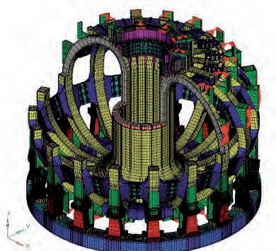
Fig. 5. TF magnets FE model (top) and details of CS (bottom left) and PF1/PF6 (bottom right) support by the TF case clamps. As shown in the left picture, the inner parts of the TF coils are ‘wedged’, forming a vault inside which the central Solenoid coils stack is inserted.
iv By AC losses we refer to the energy dissipated in the wires of superconducting cables by eddy currents as well as magnetisation currents induced therein by time-varying fields.
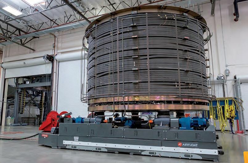
Fig. 6. The ITER central solenoid (top) is made by a stack of identically-sized CS coils (left). The first module has been wound (bottom left) and its ground insulation is applied (bottom right). Central Solenoid
PF1
PF2 Shielding Blanket
Plasma PF3
PF4
PF6
Toroidal Field Coil PF5
Divertor Vacuum Vessel
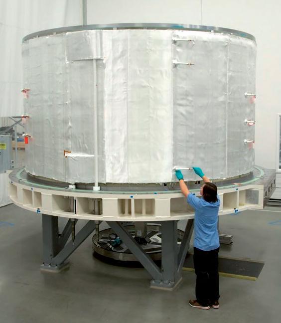
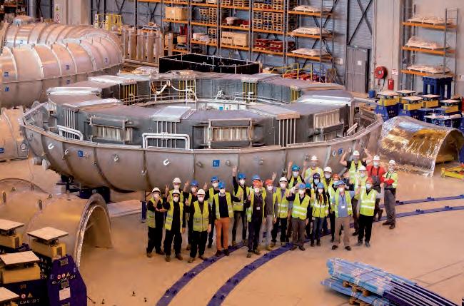
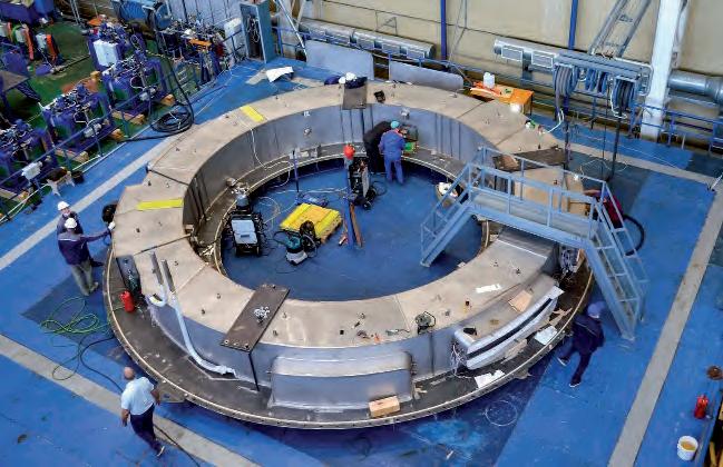
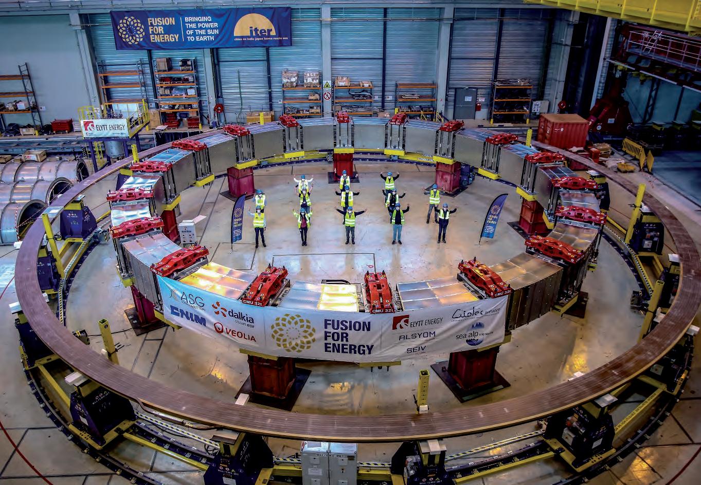
Fig. 7. Top left: ITER poloidal field coils PF6 inside the vacuum chamber for the final acceptance tests in Cadarache before being lowered into the tokamak pit. Bottom left: Final activities underway in Russia on ITER’s smallest poloidal field coil PF1 (9m in diameter). Shipment is expected before the end of 2021. Bottom right: PF5 coilwinding completed by EU DA. This coil, as well as PF4-PF3-PF2, cannot be transported by road to Cadarache and is therefore built on site.
forces are ‘decoupled’ from the TF cases support structure. Unlike the TF coils, the cyclic nature of the PF magnet system loads exacerbates fatigue-related issues in structural materials (e.g. CICC jackets) requiring careful detection of defects to avoid development and propagation. From a functional perspective, there are considerable differences between the CS coils and PF (equilibrium) coils of any PF magnet system. Indeed, the main function of the CS coils current is to generate the magnetic flux linking the plasma column while minimising the stray field leaking over the same plasma region.v By varying the CS currents, and therefore the flux linking the plasma, an electric field is generated by induction so as to drive the plasma current during its operation cycle. A useful comparison is to think of the magnetic flux generated by the CS coils as the amount of fuel needed to take off, cruise and land an airplane on a duty cycle flight. The greater the amount of ‘fuel’ (i.e. magnetic flux) in the tank, the longer and higher can the aircraft fly. The ‘cruising altitude’ reachable by our airplane corresponds to the amount of the current we can flow in operation in the plasma column. Indeed, after the plasma current is generated by the initial electric field induced by the CS coils current change (corresponding to the take-off phase of our airplane metaphor) the plasma current is steadily increased until it reaches the nominal value (cruising altitude). In ITER, as well as future reactors, once the plasma current reaches its highest value, the thermo-nuclear power-producing phase will take place. After some time, however, the CS current will have exhausted its flux availability (‘fuel reserve’) and the remaining part will be necessary to drive the plasma current back to zero (‘landing phase’). In essence, the key requirement for the CS coils in any PF magnet system is to produce as much flux as possible, i.e. to carry as much current as possible in as high a selffield as possible. At the same time, to minimise the stray field over the plasma region that would, otherwise, perturb the plasma shape (see Section 3.1) the CS coils windings are located inside the TF magnet vault with a large ratio between its height-to-radius dimension i.e. de facto mimicking an infinitely long coils. The CS coils, as well as the whole set of ITER PF coils are shown in Figure 6. In particular, the ITER central solenoid, which is manufactured by the ITER
v In the limit of long solenoid coil its current links magnetic flux but generates no field over the plasma region.
US Domestic Agency, consists of a stack of six identical CS coils as shown in Figure 6. The size of each module made it possible for them to be shipped to the ITER site after successful completion of the Factor Acceptance Tests (FATs). As far as the other PF (equilibrium) coils are concerned, their function is to shape and control the plasma column as it is formed and driven through the pre-programmed operation cycle. Similarly to the CS coils, this function requires the generation of time-varying currents. However, the magnetic field in which such coils operate is lower than the one affecting the CS and TF coils. In ITER, therefore, while both TF and CS coils are made using Nb3Sn wires, the PF coils use of lower performances (and cheaper) NbTi wires. The challenges in the makeup of PF coils relates to their dimensions. In ITER, 4 out of 6 PF coils (PF2, PF3, PF4, PF5) have diameters ranging from 16m to 24m and they must be manufactured on site since they cannot be transferred to the Cadarache site by any means of transport (Figure 7). The remaining two are built in China (PF6) and Russia (PF1) and shipped to Marseille, then transported by road to the Cadarache ITER site for final Site Acceptance Tests (SATs) prior to assembly. Specifically, PF6, built in China on behalf of the ITER EU Domestic Agency, is shown in Figure 7 prior to its installation on the lowermost part of the ITER cryostat in the tokamak pit. In conclusion, PF magnets are made of solenoid coils that operate in pulsed (time-varying) mode at different field levels. The design and operation of CS coils is most challenging since such magnets are subject to the highest magnetic fields and cyclic stresses. Their limited linear dimension and modularity make it possible for them to be manufactured and tested in dedicated facilities prior to shipment to the final assembly site. Almost complementary, PF (equilibrium) coils are subject to lower operation field and (cyclic) forces, somewhat easing the CICC design, but their large diameter (typically × 2 the plasma diameter) calls for on-site production and testing.
