


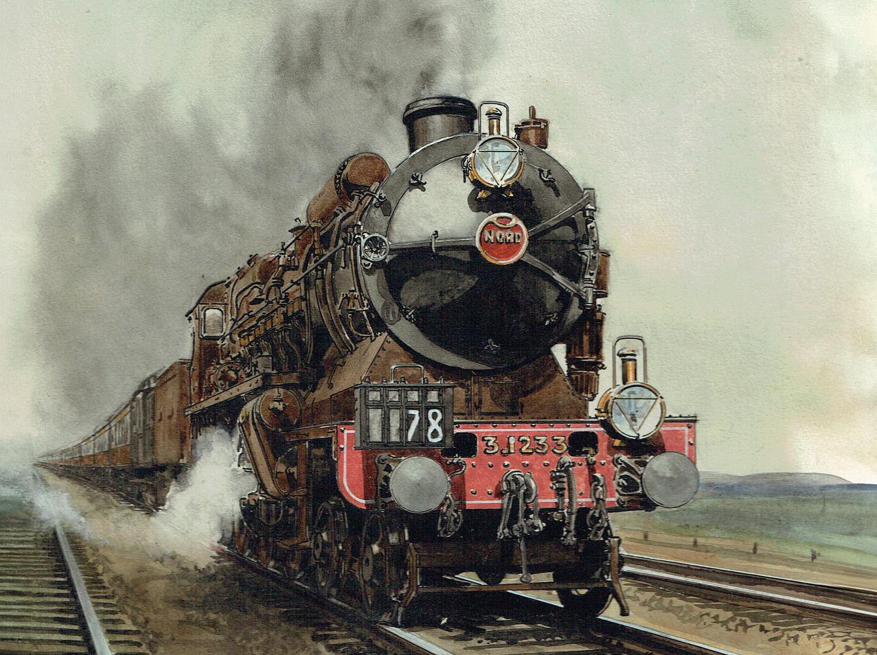

❖❖ RubySwann Better draughtingfor afiercerfire HomeFoundry Findingthebest waytolineyour furnace LNERB1 Gettingyour whistlepitch perfect WindingEngine Tandemengine getsapairof compoundcylinders GoldenArrow tacklesCaffiers Banknear Calais TREVITHICKANDHIGHPRESSURESTEAM THEORIGINALMAGAZINEFORMODELENGINEERS Vol.232No.474119April–2May2024 Joinouronlinecommunity www.model-engineer.co.uk


548 SMOKE RINGS
News, views and comment on the world of model engineering
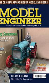
549 A TWIN TANDEM COMPOUND STEAM ENGINE
Graeme Quayle presents an interesting design for a compound winding engine
554 A VISIT TO THE CROSSNESS ENGINES
Robert Hobbs visits a rather grand and ornate pumping station in South East London
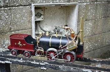
557 BUILDING 3020 CORNWALL IN 5 INCH GAUGE
Jim Clark builds a model of Francis Trevithick’s LNWR 2-2-2 locomotive
559 THE STATIONARY STEAM ENGINE
Ron Fitzgerald tells the story of the development of the stationary steam engine
563 THUNDERBIRDS!
Henk-Jan de Ruiter recalls an iconic TV puppet show
565 REDESIGNING A GAS BURNER
Graham Astbury modifies T E Haynes’s original burner design for a hot air engine to run on propane rather than town gas
567 THE AGM OF THE FEDERATION OF MODEL ENGINEERS
John Arrowsmith reports from this year’s AGM, held at the Boscombe Down Aviation Museum


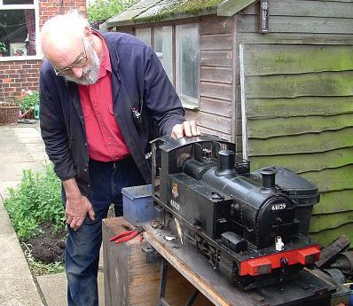
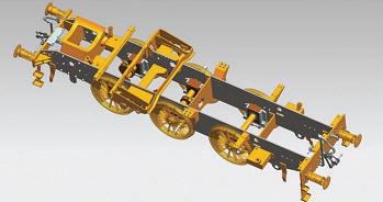
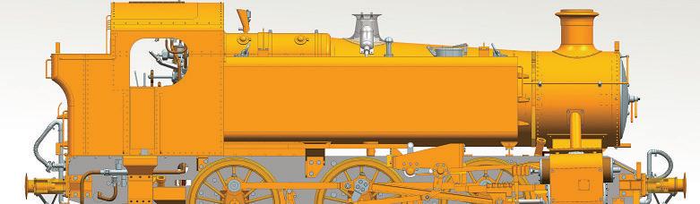
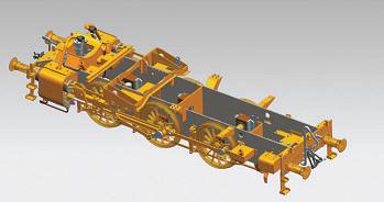
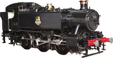
569 LNER B1 LOCOMOTIVE
Doug Hewson presents a true to scale fiveinch gauge model of Thompson’s B1
573 A CAUTIONARY TALE
Chris Rayward discovers the importance of knowing what’s in a non-ferrous alloy before trying to silver solder it
575 BUTTERSIDE DOWN
Steve Goodbody returns with further tales of the trials and tribulations of a model engineer’s life
579 LININGS FOR THE BACKYARD FOUNDRY FURNACE
Luker discusses the use of different materials for lining a home foundry
583 A LOOK AT LOCOMOTIVE 030 T 8157
Rhys Owen takes a look at a locomotive made by the SACM in France to a German design
586 POSTBAG Readers’ letters
588 WE VISIT THE NORTHAMPTON SME
John Arrowsmith spends a pleasant spring morning in Delapre Park, Northampton
Geoff Theasby compiles the latest from model engineering clubs around the world

www.model-engineer.co.uk 543
Vol. 232 No. 4741 19 April – 2 May 2024
592 CLUB NEWS
Future Events Published by Mortons Media Group Ltd, Media Centre, Morton Way, Horncastle, Lincs LN9 6JR Tel: 01507 529589 Fax: 01507 371066 © 2023 Mortons Media ISSN 0026-7325 www model-engineer co uk EDITORIAL Editor: Martin R Evans MEeditor@mortons co uk Deputy editor: Diane Carney Designer: Druck Media Pvt Ltd Club News: Geoff Theasby Illustrator: Grahame Chambers Publisher: Steve O’Hara CUSTOMER SERVICES General Queries and Back Issues 01507 529529 Monday-Friday: 8 30am-5pm Answerphone 24hr help@classicmagazines co uk www classicmagazines co uk ADVERTISING GROUP HEAD OF INVESTMENT – Lifestyle & Tractor Publications | www talk-media uk Mason Ponti mason@talk-media co uk Investment Manager: Chris Jeffery By post: Model Engineer advertising, Mortons Media Group Media Centre Morton Way Horncastle, Lincs LN9 6JR PUBLISHING Sales and distribution manager: Carl Smith Marketing manager: Charlotte Park Commercial director: Nigel Hole Publishing director: Dan Savage SUBSCRIPTION Full subscription rates (but see page 546 for offer): (12 months, 26 issues, inc post and packing) –UK £128 70 Export rates are also available, UK subscriptions are zero-rated for the purposes of Value Added Tax Enquiries: subscriptions@mortons co uk PRINT AND DISTRIBUTIONS Printed by: William Gibbons & Son, 26 Planetary Road, Willenhall, West Midlands, WV13 3XB Distribution by: Seymour Distribution Limited, 2 East Poultry Avenue, London EC1A 9PT EDITORIAL CONTRIBUTION Accepted photographs and articles will be paid for upon publication Items we cannot use will be returned if accompanied by a stamped addressed envelope and recorded delivery must clearly state so and enclose sufficient postage In common with practice on other periodicals, all material is sent or returned at the contributor’s own risk and neither Model Engineer, the editor, the staff nor Mortons Media Ltd can be held responsible for loss or damage, howsoever caused The opinions expressed in Model Engineer are not necessarily those of the editor or staff This periodical must not, without the written consent of the publishers first being given, be lent, sold, hired out or otherwise disposed of in a mutilated condition or in other unauthorised cover by way of trade or annexed to or as part of any publication or advertising, literary or pictorial manner whatsoever http://www facebook com/modelengineersworkshop http://twitter com/ modelengineers O N T H E C O V E R . . . A Type 231 Pacific of the Chemins de Fer du Nord hauls the Golden Arrow train up Caffiers Bank near Calais (from the cover of Model Engineer, October 1927) This issue was published on April 19, 2024 The next will be on sale on May 3 2024 Ruby Swann Better Bett draughting or fi fire Home Foundry Finding the best way line your furnac LNER B1 Getting yo whistle pitch ch perf ct Winding Engine Tandem engine T eng gets pair ompound ylinders Golden Arrow tackles Caffiers Bank near Calais TREV TH CK AND HIGH PRESSURE STEAM TRE K ND H E E TEA THE ORIG NAL MAGAZINE FOR MODEL ENG NEERS –SUBSCRIBE & SAVE UP TO 49% See page 546 for details www.model-engineer.co.uk 588 579
595 CLUB DIARY


SUBSCRIBE AND SAVE
Enjoy 12 months for just £68


Q uar terly direc t debit for £19
1 year direc t debit for £68
1 year credit/debit c ard for £74


Q uar terly direc t debit for £22*
1 year direc t debit for £85*
1 year credit/debit c ard for £88*
1 year direc t debit for £50*
1 year credit/debit c ard for £54*

*Any digital subscription package includes access to the online archive

Great reasons to subscribe
>> Free UK deliver y to your door or instant download to your digital device
>> S ave money on shop prices
>> Never miss an issue
>> Receive your issue before it goes on sale in the shop
D I G I TA L
I G I TA L O N LY
R I N T O N
P R I N T +
D
P
LY
classicmagazines.co.uk/ M E D P S 01507 529529 and quote MEDPS Lines are open from 8.30am-5pm weekdays GMT O fe r e nds D e ce mb e r 31, 2024 Subscriptions will s t ar t w ith the ne x t availab le issue D ire c t D e bit p ay me nt s w ill continue on the agre e d p lan unless you te ll us othe r w ise To v iew the privac y p o lic y for MMG Ltd (pub lishe r of M o de l Engine e r), p lease v isit w w w. mor tons .co.uk /privac y Pl e ase v i s i t w w w.c l ass ic m ag a z i ne s .co.u k / te rm s for fu l l te rm s & con d i t ions . ( 8
Changing Times


 DIANE CARNEY Assistant Editor MARTIN EVANS Editor
Over the Easter weekend I visited a garden railway in Lincolnshire It was good to see many old friends again but the emphasis is on the word ‘old’. We are all getting older and one of the main topics of conversation was artificial hips and knees and not being able to enjoy our hobby as we used to Times are changing – as they always do
Our hobby is changing too – again, as it always has It is, after all, only for a couple of hundred years or so that we have had the modern centre lathe or standardised screw threads Many model engineers still remember using a treadle lathe. It seems the rate of technological progress steadily accelerates and now we have CAD, CNC, 3D printing and laser cutting, and all easily accessible I have omitted investment casting as that is in fact one of the oldest technologies we use - the Ancient Egyptians used it to make gold jewellery, for example
them as a ‘nuisance’ and not ‘real’ model engineers ‘They don’t know how to drive it’, ‘they don’t know how to maintain it’, ‘what happens when it goes wrong?’ – these are all legitimate complaints but they also represent an opportunity. The first is that these enthusiasts have at least shown an interest by buying a locomotive (at significant expense) and joining the club – and they have paid their subscriptions New members are what clubs need and so they should do everything they can to encourage new entrants to the hobby Our discussion in Lincolnshire focussed on what clubs could do to cultivate the interest of these new members
that with the name of the article Any content in the message will not be relevant to the vote (This keeps counting the votes simple for me ) Alternatively, if you don’t have access to email, you can write to me with your vote. In the event of a tie the editor will have the casting vote
The result will be announced in June
IMLEC
Mar tin Evans can be contacted on the mobile number or email below and would be delighted to receive your contributions, in the form of items of correspondence, comment or ar ticles.
07710-192953
MEeditor@mortons.co.uk
Other aspects of our hobby have changed too There is no denying that it is a smaller hobby than it was. A major factor, I think, is that the skills of the workforce have changed over time and far fewer people are trained in the skills that underpin model engineering I remember we had woodwork and metalwork classes at school, which at least provided everyone with the basic skills, but that appears no longer to be the case This represents a higher ‘barrier for entry’ to the hobby One result is that many who come into the hobby no longer build their own locomotives – they buy them second hand or new from an increasing number of manufacturers or as ‘bolt it together’ kits
This represents a challenge to clubs Purchasers of ‘ready-made’ locomotives need to join a club if they are to renew a boiler certificate for their locomotive but it is too easy to see many of
The two most important things, we agreed, were involvement and education - get the new members behind a locomotive as soon as possible, teach them how to drive well, show them how to look after their locomotive In other words, turn them into ‘real’ model engineers A key idea that came up was that clubs should assign a ‘mentor’ to new members to guide them through the process
Yes, times are changing, but there are plenty of opportunities for clubs to adapt to change and to maintain and encourage interest in our hobby.
Bradford Cup
The nominations for the Bradford Cup are now in and it’s time to start voting! The Cup is awarded to the best article or series in Model Engineer during the year 2023 We have had only three nominations again this year, as follows:
The Stationary Steam Engine – Ron Fitzgerald
Radial Valve Gears Again –Duncan Webster
Fire Queen – Luker
Please register your vote with me before the end of May –one vote of course per reader The simplest way of doing this is by email (MEeditor@ mortons co uk) In that case please start the subject line with ‘Bradford Cup’ and follow
Here is a reminder that if you wish to compete in IMLEC this year you need to get your application in soon I hope that you will already have applied to Ben Pavier (publicity@ southportmodelengineering club or mobile 07882 259845) for an application form or requested one via the website These should then be returned to Ben The closing date for applications is May 10th
This year’s event is promising to be rather more than just a competition We are promised trade stands, including Polly Model Engineering, and craft stalls A marquee will be available so getting wet when it rains will be optional There will be live music on Saturday evening and food will be available. Currently this is likely to be either curry or chilli. Travelodge and Premier Inn are nearby and camping is also available
So – this is not just any old competition, this is a Southport MEC event and takes place from Friday to Sunday, July 19th – 21st Further details can be found on the web at southportmodelengineering club

Model Engineer 19 April 2024
548 IMLEC
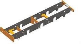
A Tw i n Ta n d e m T Compound Steam Engine C

Graeme Quayle presents his own design for a compound winding engine
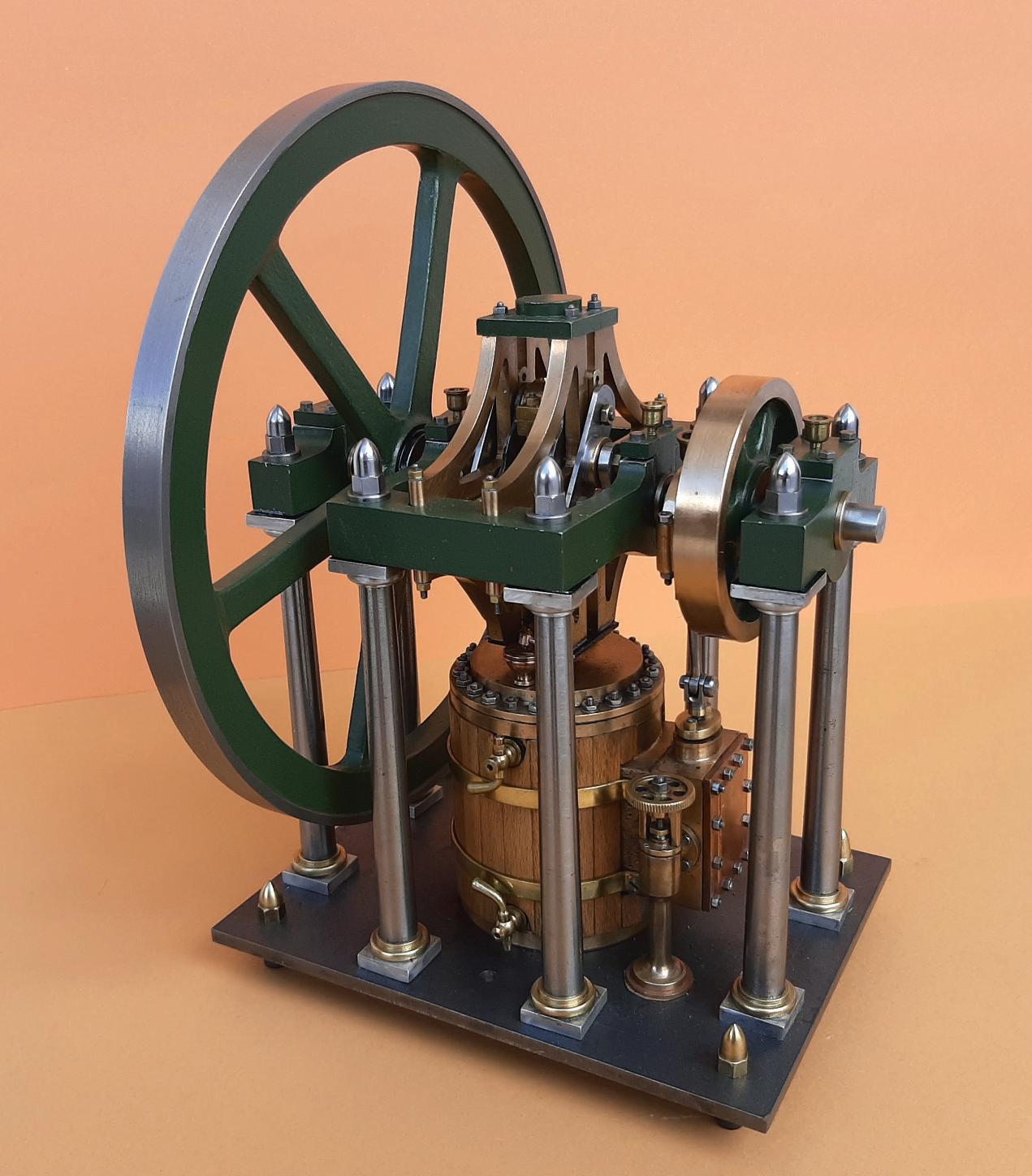
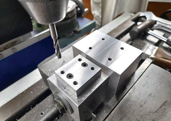
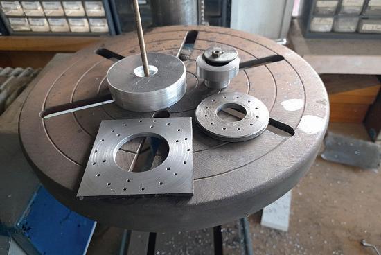
The machining of the cylinders was easy to do with the square blocks
The holes for the bronze bushes were bored and the one face was also skimmed at that time That face should be marked so that it is used to mate to adjoining parts to ensure all the built-up parts for the cylinder assemblies are kept truly in line On my engine I added a pad to the base of the HP cylinders to make them up to the same level as the base on the LP cylinder (fgs 3 and 4) This can be done away with if a 62mm long square piece of two inch square is used for the HP cylinders They were then spigotted together and the mounting faces machined Continued from p 525, M
549 www.model-engineer.co.uk >>
P
T 2
A R
25 50° 50° 45° 40° 22° 12 holes Ø2 1 x 12 Tap M2 5 Drill 6 holes equi-spaced Ø2 1 on 53 PCD Tap M2 5 one face Drill 3 holes each flange Ø1 25 x 6 deep Tap M1 6 Ø3 Drill Ø4 2 & tap M5 x 12 deep Low Pressure Cylinder Mat’l: Aluminium 2 off Ø6 35 (1/4 ) x 27 deep Tap 9/32 x 32 ME 6 deep Drill 18 holes equi-spaced Ø2 1 on 68 PCD Tap M2 5 both faces Ø74 Bronze bush 40 I D x 45 O D 50 long, press fit in alum body 18 9 2 2 5 25 6 1 5 2 4 10 30 22 5 20 8 2 5 3 4 1 3 4 1 4 1 2 1 2 2 6 3 8 6 6 1 1 7 4 0 2 5 1 0 6 2 1 0 1 5 50 11 12 50 11 11 11 85° 85° 45 40 40 45 45 10° 12 holes Ø2 1 x 12 Tap M2 5 Drill 3 holes each flange Ø1 25 x 6 deep Tap M1 6 Drill Ø5 through x 12mm then Ø4 2 x 10 deep tap M5 High Pressure Cylinder Mat l: Aluminium, 2 off Drill Ø5 7 x 23 deep Tap 1/4 x 40 ME 6 deep Ø2 5 Ø50 7 5 20 42 5 35 7 5 25 50 5 40 2 5 7 5 10 2 5 11 11 11 18 9 17 15 Drill 12 holes equi-spaced Ø2 1 on 43 PCD Tap M2 5 both faces Bronze bush 25 I D x 35 O D 50 long press fit in alum body 3 6 1 5 2 4 1 2 3 8 3 5 1 1 3 5 6 6 7 2 6 2 5 7 5 4 2 5 3 5 2 5 8 8 1 4 1 2 1
E 4740 April 5
Fig 3
Low pressure cylinder.
Pressure cylinder
Fig 4
High
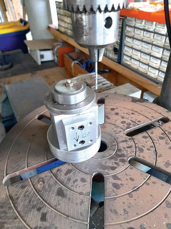
with a y cutter (photo 4) The cylinder mounting holes for the HP and the LP cylinders were then drilled and tapped (photos 5 and 6).
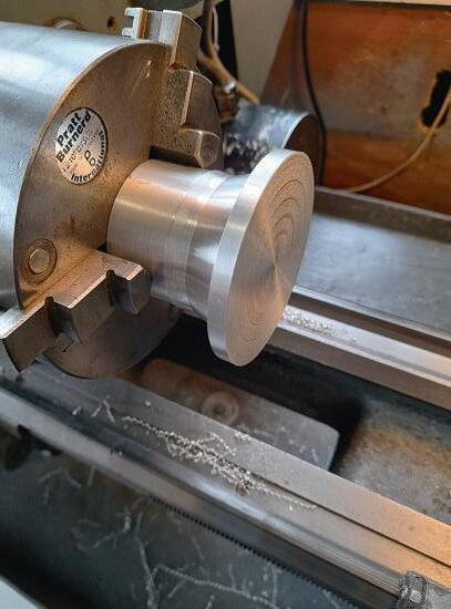
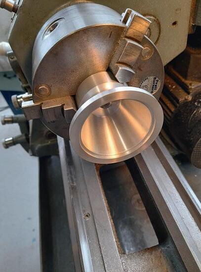
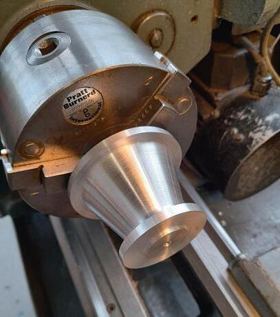
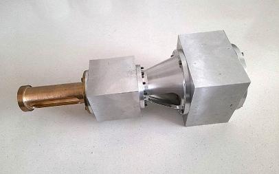
The tapered connector was machined out of round aluminium bar and the first stage was to rough out the smaller end leaving a good chucking boss (photo 7 and fg 5) The second stage was to bore out the tapered inside and finish the outside portion of the big end (photo 8) Then by gently holding the part, the small hal was finish turned (photo 9) Continuing with the connectors, the side holes were milled with a long series mill with the vice angled to do the sloping sides (photo 10) If a long series milling cutter is not available then each side can be done separately as these cut outs only give access to the gland nuts
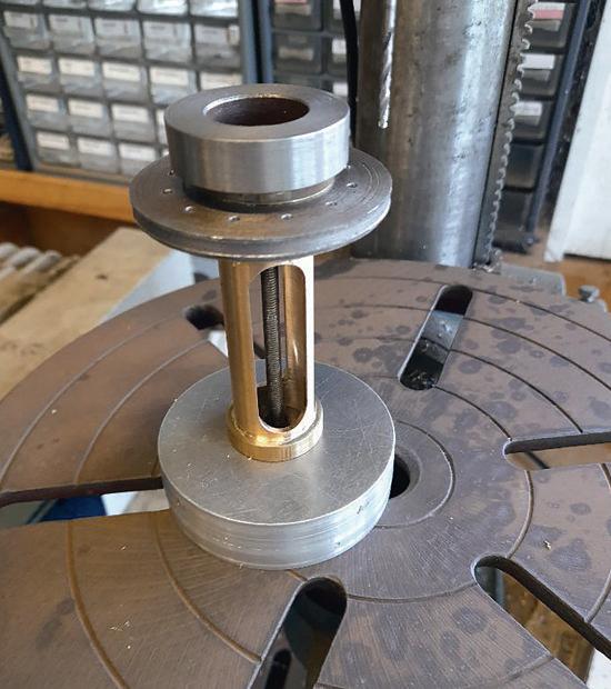
The trunk guides were then prepared and the parts silver soldered together (photo 11) After they had been cleaned up and the ange ace machined square to the bore they were
550 Model Engineer 19 April 2024
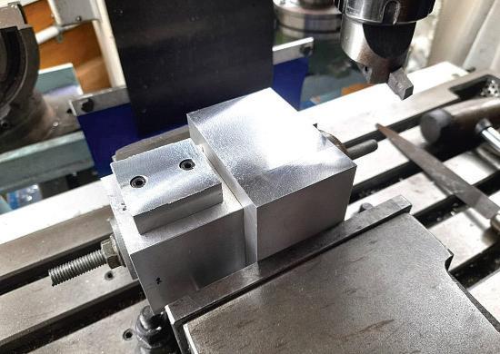
The bases being machined
The clamping parts showing the stepped spigot, used again for drilling of the holes
Tapping the cylinder mounting holes
First stage machining of the tapered connector
Final stage fnishing the outside
Second stage boring the inside
4 5 6 7 9 8 10
Milling the side holes with a long series mill
The silver soldered trunk guides.
set into the milling vice and the slots milled (fg 6) Cautionary note here - the slots should be opened out gradually and most important the milling cutters should be sharp (photo 12) The other end covers can be machined up at this stage so that they can be drilled while
the drill jigs are being used
For the drilling of the radial holes in the various parts I made two drill jigs; the smaller round one has a spigot hole in the centre to match the bore of the HP cylinder and the other larger square drill jig has the bore to suit the LP cylinder
551 C O M P O U N D E N G I N E www.model-engineer.co.uk >> r8 r8 Drill 18 holes equi-spaced Ø2 6 on 68 PCD Drill 18 holes equi-spaced Ø2 6 on 68 PCD Drill 12 holes equi-spaced Ø2 6 on 43 PCD Drill 12 holes equi-spaced Ø2 6 on 43 PCD 4 holes equi-spaced drill Ø2 1, tap M2 5 Csk for screw heads Drill Ø10 2 Tap M12 2 2 48 40 51 5 15 17 5 5 1 5 20° Ø 6 1 Ø 1 6 Ø28 Ø25 Ø20 Ø74 Ø60 Ø40 Ø50 Ø 5 Ø 5 Ø 6 1 Ø 5 0 Ø 3 6 Ø 2 5 Ø 7 4 1 2 3 7 Ø 6 3 5 ( 1 / 4 ” ) Ø 5 9 Drill Ø10 2 Tap M12 11 5 11 5 1 5 1 5 7 7 3 8 8 5 5 Drill Ø10 2 Tap M12
Cylinder
Covers And Joiner
Section Mat’l: Aluminium, 2 off each Low Pressure Cylinder Cover High Pressure Cylinder Cover
5
Cylinder Joiner Fig
Cylinder covers and joiner section
Milling the slots in the trunk guides
11 12
552 Model Engineer 19 April 2024
Drill 12 holes equi-spaced Ø2 6 on 43 PCD
Drill 6 holes equi-spaced Ø2 6 on 53 PCD Csk Ø6
74 72 - bronze bush 36 8 3 16 11 5 8 2 1 5 16 40 Slot through Ø8 Ø 2 8 Ø 2 0 Ø50 Ø60 Ø6.35 (1/4”) Ø40 1 4 r7 8
Brass oiler, drill with Ø6 x 6 deep, through Ø1 5 & soft solder to bush
Commercial bronze bush Ø20 x Ø24 x 80
long
Soft solder brass bush to main bush
Rebate bronze bush into brass disc x 1mm & silver solder in place
Skim this face true to bore of bush
Cylinder Covers And Trunk Guide Mat’l: Aluminium, 2 off each
Trunk Guide 2
6
LP Inner End Cover Mat’l: Aluminium, 2 off
off Fig
Cylinder covers and trunk guide
The small circle drill jig drilling the tapered part
13 14
The small circle drill jig drilling the HP cylinder
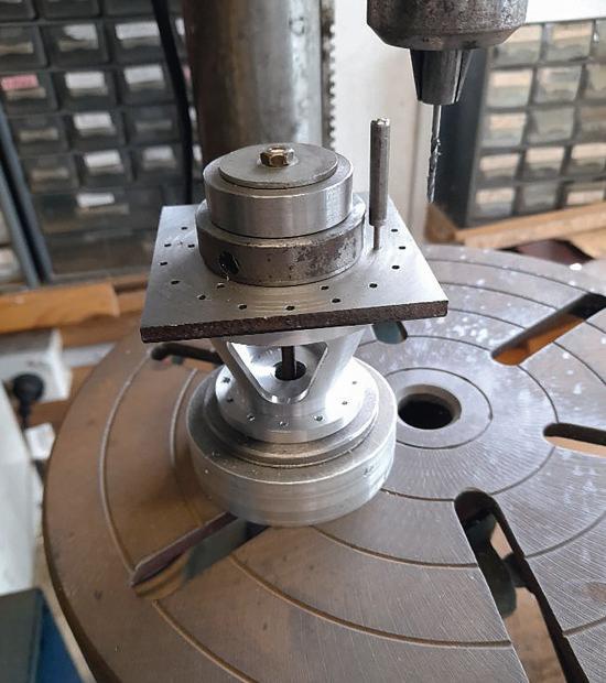
(photos 13, 14, 15 and 16)
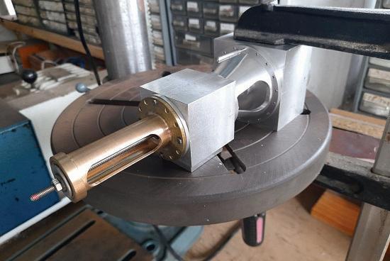
The holes in the LP cylinder needed to be lined up to the ones in the HP cylinder and connector By clamping the parts together, a small punch was used to
The holes in
not have
to be exactly right radially (photo 18)
After all the holes had been drilled it was time to tap the threaded holes and to drill out the clearance holes as
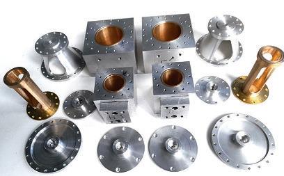
required Drilling and tapping of the many holes is a timeconsuming job for which an aluminium tapping uid is essential as well as a tapping jig to hold the taps straight There are well over 200 tapped holes in the cylinders alone so if tapping holes is not your thing then do not start this model At this stage the components were assembled to check that all was okay (photo 19 The final photograph shows the parts with all the radial holes done - still plenty more holes to do though (photo 20)
To
553 C O M P O U N D E N G I N E www.model-engineer.co.uk
The small circle drill jig drilling the trunk guide
A small punch used to mark the top LP cylinder hole
The basic HP connector piece and LP cylinders assembled The cylinder components with all radial holes done
The large circle drill jig drilling the tapered piece
The drilling jig parts mark the top hole in the LP cylinder, then the large drill jig was used to drill the holes in the LP cylinder (photo 17)
the outer ends of the cylinders do
be continued 15 17 19 20 16 18
A V i s i t t o t h e C r o s s n e s s E n g i n e s

Continued from p 531
M E 4740 April 5

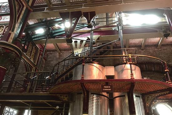
The four engines in the building, set around the central octagon, were originally supplied by James Watt and Co in 1864 and were named after members of the royal family at that time, namely
Victoria, Prince Consort, Albert Edward, and Alexandra Watt and Co up-graded the engines in 1889 and again in 1892 when Benjamin Goodfellow and Co Of Hyde, Manchester, replaced each of the engines’
four plunger pumps with a pair of nine foot diameter pumps shifting over six tons of sewage at each stroke A new engine house was built in 1898 where Flemming and Ferguson installed two triple expansion
554 Model Engineer 19 April 2024
Robert Hobbs visits a preserved pumping station in South East London
P A R T 2
odel o the e
Crossness
ised engine onfgu ation. he ain ea o Prince Consort
he ain ea i ot 12 13 14
engines and pumps in 1899 and in 1901 Benjamin Goodfellow and Co commenced upgrading the original engines The single cylinder and piston of each engine was replaced by a new triple cylinder arrangement, which entailed rebalancing the engine with an intermediary beam and counterweights
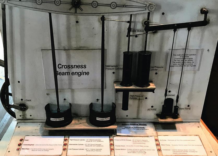
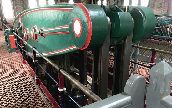
In photo 12 a model of the engine installation operation
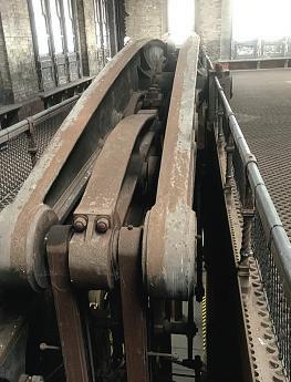
is illustrated within the engine house. Ascending the beautifully detailed and painted staircase to the beam oor the enormity of the main beam is brought into perspective, weighing in at 47 tons each and moving so gracefully it is di ficult to believe you are witnessing an engineering marvel that is over 158 years old hotogr ph 13 shows
the main beam on Prince Consort with the second engine, Victoria, undergoing its restoration in the background
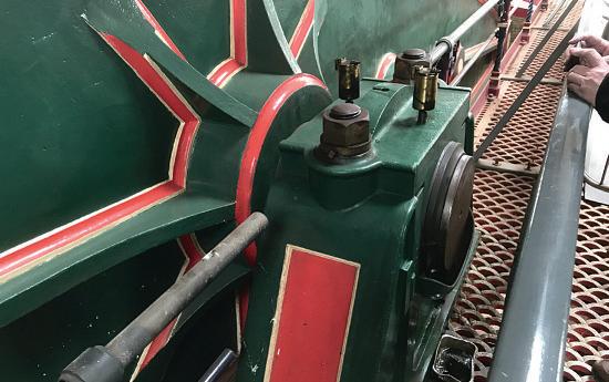
The bright steel work of the James Watt straight line motion on Prince Consort is finished to an incredibly high standard, as are all the controls and valve gear on the engine
Photograph 13 shows the level o finish is e tremely high and
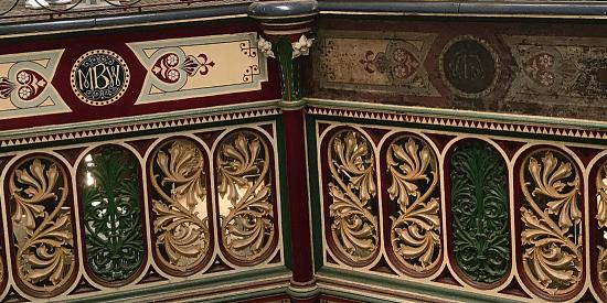
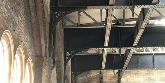
a credit to the volunteers who look a ter this magnificent engine Photograph 14 shows the massive plummer block that provides the pivot for the main beam and, once again, the quality of the painting and lining of the installation is evident and this quality is further illustrated in photo 15 which shows a section of the upper octagon with a ‘before’ and ‘after’ painted panel The main beams supporting the roof of the building and their end supports were not neglected in their design extravagance with the MBW logo being cast in each end bracket, which was also mounted on a carved pedestal at the lower end These beams and supports are shown in photo 16
The two remaining engines at the eastern end of the building are unlikely to be restored; the aim of the trust is to stabilise them so they do not deteriorate further These two engines are no less impressive despite their dirty and dusty situation
Photograph 17 shows the main beam of Alexandra sitting serenely like a sleeping giant It was probably the sheer size of these four beams, 47 tons each, that saved these engines from being scrapped and dismantled in thanks to the significant economic problem of dealing with them in situ.
Having been wowed by the beauti ully finished upper level of the Prince Consort engine, we returned to the lower oor and were once again impressed by the overall beauty of it
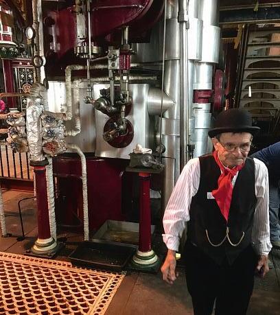
(photos 18 and 19) At this time we were fortunate enough to be in conversation with the afternoon Engine Operative, Ray Fleming (photo 20) Ray
555 C R O S S N E S S www.model-engineer.co.uk >>
anels on the u e o tagon esto ed and un esto ed he st u tu e o the oo
he ie o eneath Prince Consort
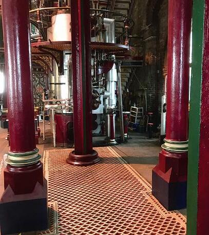
illa s su o ting the u e le el.
Alexandra, one o the t o un esto ed engines
15 17 18 16 19 20
a Fle ing attends to the engines.
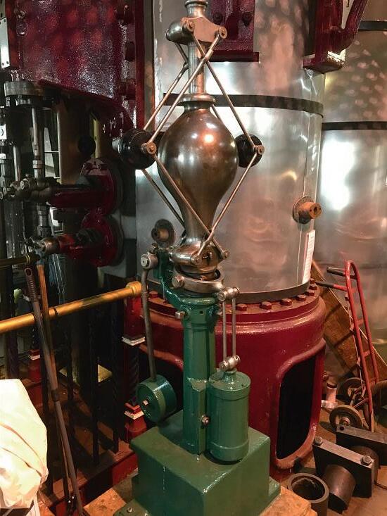
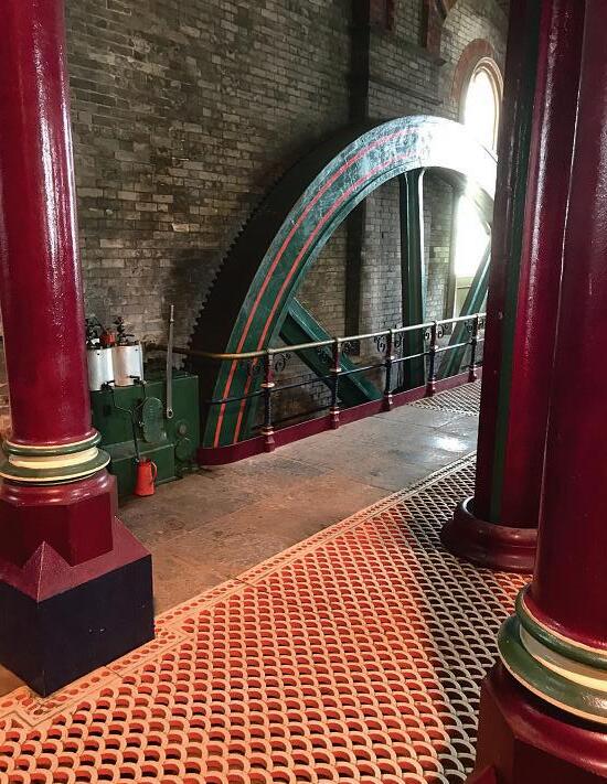
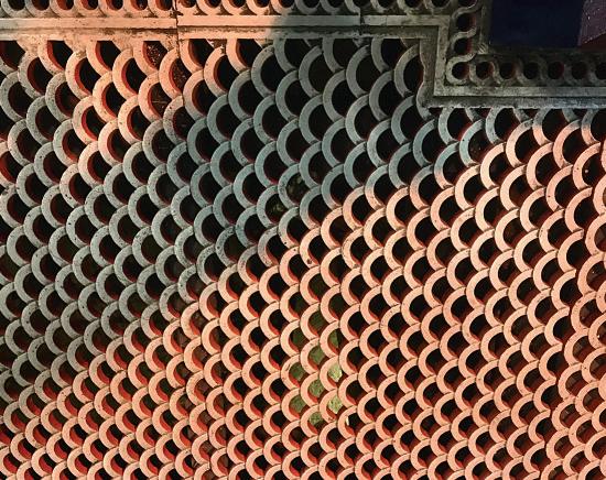
explained the working of the Porter governor (photo 21) that was being readied for Victoria and how the ooring which we thought looked like fish scales (photo 22) was in fact representative of the waves in the nearby Thames The grating oors together with the central octagon allowed the natural light to penetrate the lower levels and eliminate the accumulation of the highly explosive methane gas, a derivative of sewage Candle, gas and oil lighting were, of course, totally inappropriate. Prince Consort had been stationary for a while and we were invited to see the restart using the steam powered barring engine This is the square box on the left-hand side o the main ywheel in photo 23 This small engine manoeuvres the massive 52 ton ywheel into the correct position by engaging with teeth around the ywheel s periphery This puts the valves in the correct position for the engine to start running. In photo 24 you can see a line across the ange
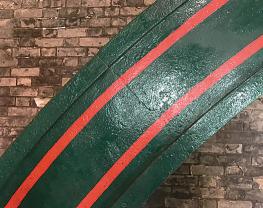
o the ywheel this is where two of the cast sections of the ywheel are oined t seems appropriate to finish our visit here with the start-up of one of these magnificent engines
This is definitely a site worth visiting, whether you are an engineer or not; the people are friendly and the engines are magnificent The valve house has an exhibition of pumping machinery and the engineering workshop has an impressive array of lathes and milling machines etc su ficient to handle most refurbishment repairs on site. The Trust has an ongoing plan committed to preservation, education and awareness of the responsibilities of looking a ter this magnificent piece o Victorian engineering
Many thanks to all of the volunteers on site, especially Bob and Ray for the most interesting discussions, for Kevin Ridley for patiently answering my questions and to The Crossness Engines Trust This can all be found at:
The Old Works
Thames Water S.T.W., Bazalgette Way
London SE2 9AQ
Tel 020 8311 3711
www. crossness.org.uk
We are grateful to the Trust for allowing the publication of this article in the Model Engineer magazine
556 Model Engineer 19 April 2024
Victoria’s o te go e no
Fish s ale atte n on the oo e esenting the ate s o he ha es
ME ain heel ith a o an ing a ing engine he heel is ast in se tions and oined 21 22 23 24

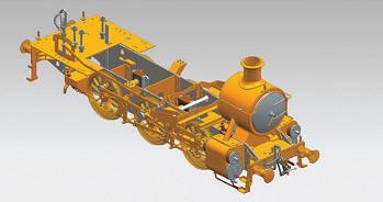
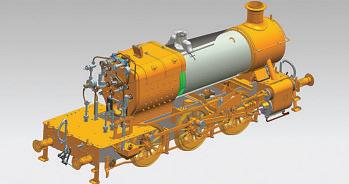
Jim Clark builds the famous LNWR 2-2-2 – the frst locomotive earmarked for preservation
Continued from p 499
M E 4740 April 5
Smokebox and chimney details.
The smokebox
This is a very important item, being literally front and centre of the locomotive as you look at it, so I took some time and effort to try and get it looking
as close as possible to the original (fg 14)
The smokebox barrel was rolled up from some 3mm stainless steel sheet and TIG welded along the seam
I had an off-cut of a large bronze hollow bar which I brazed into the end to form the door mounting ring For convenience, I cast a brass slug which I could machine up
This shows the completed smokebox door, placed on the photo of the full-size engine for comparison I think the model door turned out to be a pretty good replica of the real thing! Rough door casting at left, barrel fabrication at right
557 www.model-engineer.co.uk >> B U I L D I N G 3 0 2 0 CORNWALL WAL in 5 Inch Gauge PA RT 4
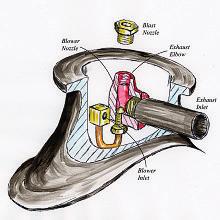
Smokebox 1 0 4 Ø110 Smokebox Mounting Ring Ma Fabr cate rom 2 4mm brass s r p Si d t D&T fo sc ews to bo er shel D&T fo csk screws to smokebox Smokebox Shell Ma l Fab ica e f om 3mm sta n ess stee Smokebox Assembly We d o nt g Smokebox Front M t F b f 5 b S ver so de smokebox fron nto smokebox she Ø81 Ø102 23 10 Dr or 1 6mm r ve s 47 5 PCD 46 4 1 2 5 5 Dr or door hinge (sc ew rom ns de 2 2 5 39 Smokebox Door Assembly Rivet & s ver so de bracke s o ns de Smokebox Door Locking Bar Mat Fabr cate from sta n ess stee 90 6 8 Ø22 2 5 Locking Hand Wheel & Lever Ma : Fab ca e f om 1 6mm sta nless s ee od so dered to hub D&T 6BA 3 Ø6 2 6 Locking Dart Mat Fabr cate from s a n ess stee 28 Th ead 6BA B aze o we d S d k b f on into smokebox Smokebox Door Hinge Components Mat Brass w th sta n ess p n 2 Pro i e to ma ch doo S lver solde o door 3 0 Handle Mat Brass 1 4 4 5 Ø85 ØØ77 81 Cy nder nlet c/ L t h f t p t on cy inder covers t p a n bushes at same ang e as cy nder cove s Cy nder in et c/ Ch mney & exhaus c/ Chimney & exhaust c/ Exhaust 80 F pla n bush on ch mney c/ F pla bush on exhaus c/ Ø40 Ø60 Ø36 Ø104 To match D of boi er she 1 1 0 Ø40 Ø36 Ø60 Ø40 Ø37 Ø34 1 2 Chimney Cap Mat B ass o bronze) 1 0 2 9 5 1 5 Chimney M t B t Chimney Retaining Ring And Petticoat D mp e for retain ng sc ew D&T or e a n ng screw Fab cate pet coat f om coppe shee or tube & s ver solde o r ng Exhaust & Blower Manifold Ma l Fab ica e f om brass 8 ° Ø30 B owe in e B ower nozz es Ø0 8mm or f ce B ast nozz e S a t w th Ø3mm o f ce & d t t d ght Steam n e f t ing screws nto port n s eam ches cove E h t f d sc ews n o bush on exhaust p pes
Fig 14 27 28
29 30 31 33
32
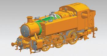
e e is the s o e o and hi ne o leted ainted and ftted
for the smokebox door itself
(photos 27 to 32) This turned out to be one of the only two
castings that I used in the whole build, but it could just as easily be turned up from a slice
cut off a brass or bronze billet
In fact, I now had a complete and working chassis and I was able to test run the engine on compressed air, using the two copper pipes and a rubber hose seen in photo 32 hanging out of
the smokebox (photo 33) This was a great day, and it was very satisfying seeing those big wheels rotating under their own power or the first time
To be continued
558 Model Engineer 19 April 2024
Turning the door casting
The next job was to set it up on the chassis. The vertical brass bar is being used to ensure the blast pipe is directed straight up the centre of the chimney and to keep it vertical
For completeness, a view inside the smokebox of the completed engine, showing the e haust ani old etti oat and othe inte nal fttings.
his sho s the s o e o a el a i ation ith its fttings the hi ne and the door
Ron Fitzgerald takes a look at the history and development of the stationary steam engine.
Continued from p 462, M E 4739, March 22
T h e S t a t i o n a r y S t e a m E n g i n e
PART 56 – THE HIGH-PRESSURE STEAM ENGINE AND THE FIRST CORNISH STEAM WHIM ENGINES
Trevithick’s involvement with the water pressure engine may have been partly a reaction against Boulton and Watt’s restrictive practices but it was to bring significant positive consequences Water engines were safely operating with pressures up to 100 psi, whereas the Watt type engine rarely approached 10 psi Trevithick must have observed that such pressures meant greater power with a relatively smaller cylinder diameter
It was also suspected that the water pressure engine operating without a draught tube incurred only a marginal loss of power which raised the analogous question, what would the effect be on the steam engine if the condenser was removed and the steam pressure was correspondingly raised to compensate for the loss? Trevithick turned to Davies Giddy for a theoretical answer to such questions
Giddy was three years older than Trevithick His father, the Rev Edward Giddy, was a keen amateur mathematician and after personally tutoring his son he sent him to study under the Rev. Malachy Hitchins, an Oxford trained mathematician who had worked with the Astronomer Royal, Nevil Maskelyne (ancestor of the Model Engineer’s J N M) At the age of 17, Giddy joined the Bristol mathematical academy of Benjamin Donne where he stayed for three years, subsequently attending Pembroke College, Oxford, and graduating M A in June,
1789 Giddy’s competence in mathematics and the sciences was outstanding; amongst his achievements was one of the earliest English appreciations of Eulerian calculus, at that time an almost exclusively continental affair that, once accepted in Britain, was to supplant ewtonian u ions as the mathematical orthodoxy
In 1791 Giddy was elected a Fellow of the Royal Society and was later president He was also a member of the Royal Institution and promoted his fellow Cornishman, Humphrey Davy, as a candidate for his first scientific post as Demonstrator of Experiments in the Institution’s laboratory Although heavily involved in London’s intellectual society he maintained his native roots with a home in Cornwall He was High Sheriff for the county from 1792 to 1793 and M P for Helston and Bodmin To the confusion of historians, Giddy changed his name to Davies Gilbert in 1816 when his father-in-law died, leaving Giddy his property in Sussex By 1790, as an established consultant in matters of engineering he was on intimate terms with Thomas Telford whom he frequently advised. The Cornish steam engine builders relied heavily upon his knowledge and in contending with the Cornishmen, Boulton and Watt found cause to fear him as an adversary
In 1839 J S Enys had written to him enquiring about his relationship with Richard Trevithick Gilbert replied: about the year 1796 I remember
hearing from Mr Jonathan Hornblower that a tall and strong young man had made his appearance among engineers and that on more than one occasion he had threatened some people who contradicted him to fling them into the engine shaft. In the latter part of November that year I was called to London to witness in a steam engine cause between Messrs Boulton and Watt and Maberley There I believe that I first saw Mr Richard Trevithick Jun , and certainly there I first became acquainted with him Our correspondence commenced soon afterwards and he was frequently in the habit of calling at Tredrea to ask my opinion on various projects that occurred to his mind---some of them very ingenious and others so wild as not to rest on any foundation at all…
On one occasion Trevithick came to me and inquired with great eagerness as to what I apprehended would be the loss of power in working an engine by the force of steam raised to the pressure of several atmospheres but instead of condensing to let the steam escape I of course answered at once that the loss of power would be one atmosphere diminished power (compensated for)… by the saving of an air pump with its friction and in many cases with the raising of condensing water I never saw a man more delighted and I believe that within a month several puffers were in actual work
iddy confirmed Trevithick s intuitive idea that the separate
559 www.model-engineer.co.uk >>
condenser might be eliminated without detriment if the engine was worked with a compensatory higher steam pressure Unfortunately, Giddy does not give a precise date for the meeting but it must have been later than November 1796, the date which he gives for the Hornblower/Maberley legal challenge
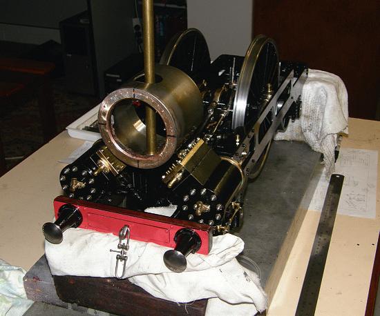
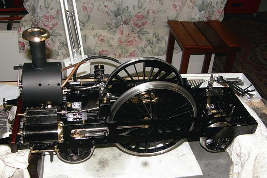
Firm dates are also lacking for the events that followed but it would seem that a series of models were built as progenitors to Trevithick’s full-scale development of the non-condensing, highpressure steam engine The source for this information is Francis Trevithick, whose mother, Jane, provided the original account (ref 289). Mrs. Trevithick recalled a model
of a high-pressure engine built by William West in 1796 or 1797 West (1751-1831) was an established Cornish clockmaker and a versatile craftsman who was said by James Bolitho to have worked with Trevithick and Bull on the Ding Dong engine in 1792 (ref 290) He was married to Joanna, daughter of the Hayle ironfounder, Edmund Harvey and sister of Jane who married Richard Trevithick West was to be closely associated with Trevithick for the next twentyfive years
Apparently, the model described by Mrs Trevithick was made to support her husband’s case in an impending law suit with Boulton and Watt of which no further evidence has come to
light The model was made of brass and the boiler resembled an iron kettle with a fire underneath She remembered Davies Gilbert acting as stoker whilst blowing the bellows whilst Lady Dedunstanville was engine man Jane Trevithick’s statement represents the extent of surviving knowledge concerning this the first model high-pressure engine The description of the steam generator as kettle-like gives the impression that it was probably modelled upon the common brewer’s tun or haystack boiler and that it had a solid uel fire which would re uire artificial dra ting with bellows to sustain combustion
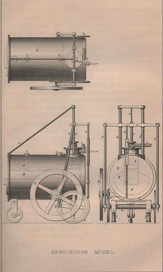
Jane Trevithick also described a second model which rancis identifies and illustrates in the Life (ref 291 and fgs 179 and 180). She said that it was built shortly a ter the first model and that it was capable of moving under its own power, describing how it ran around the table
Through the agency of Francis, the model was identified in the eighteen-sixties as surviving in Manchester and eventually came into the possession of the atent fice useum latterly the Science Museum (In 1804 the model was held by Whitehead and Co., Soho Iron Works, Manchester, who were said to have used it as a guide when manufacturing Trevithick style engines It passed into the hands of Joseph Radford’s family in 1810 and remained so until 1850 when it was donated to the atent fice Museum ) Jonathan Minns gave it a date of 1796 (ref 292) but this is almost certainly his interpretation of Francis Trevithick’s dates of 1796 or 1797 In the light of Giddy’s statement regarding the date o his first meeting with Trevithick, 1797 is probably more accurate
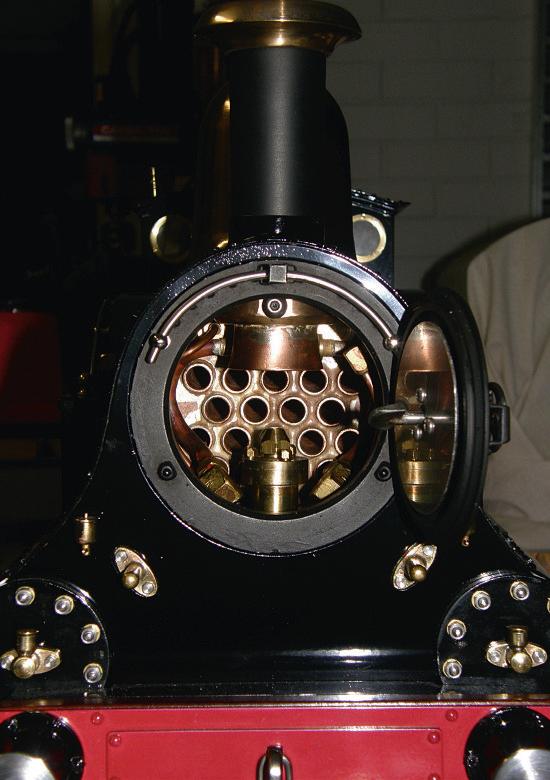
The boiler shell is made of beaten and soldered copper and contains an internal firebo at one end but without any e haust ue system or chimney According to Trevithick the boiler was filled with boiling water and ebullition
was maintained by placing a piece of red-hot iron into the fire chamber a techni ue used to heat tea urns at that period
The single, vertical, doubleacting, cylinder has a bore of 1 55 inches and a stroke of 3 4 inches (fg 181) It is located at the opposite end to the fire chamber and is sunk vertically into the boiler. Steam admission and exhaust are controlled by a semi-rotative plug cock actuated by a vertical valve rod connected to and reciprocating with the crosshead The valve rod is slotted and a lever connected to the plug cock is inserted into the slot to be alternately tripped open and closed as it strikes the upper and lower ends of the slot
The two driving wheels of the model are rotated by connecting rods from the crosshead to crank pins set into the wheels. A single, smaller diameter, third wheel is attached to the underside o the boiler at the firing end
One of the driving wheels has a gear attached to its rim which engages with a spur wheel on a stub axle that carries a ywheel This ywheel served to regularise the piston cycle but it was also a possible power take-off Small screw jacks are mounted under the driving wheel bearings which raised the wheels above the ground when the engine was to be used as a stationary power source
This model represents a substantial departure from established beam engine practice for in addition to being an exploration of the potential for a high-pressure, non-condensing steam engine it also provided the means to avoid Watt’s other patents By the direct connection between the piston rod and the crank, Trevithick secured rotative motion without reference to the parallel motion patent and to a lesser extent, the sun-and-planet gear patent, both enforceable until 1800 It is a compact and portable source of rotative power and, as Trevithick would have appreciated, it could be readily
560 Model Engineer 19 April 2024
Francis Trevithick’s engraving of the second model
Fig 179
