STANFORD UNIVERSITY
Central Energy Facility
Stanford, California

 PHOTOGRAPHER © Matthew Anderson

PHOTOGRAPHER © Matthew Anderson
Stanford, California
OWNER
Stanford University
LOCATION
Stanford, California
DATE COMPLETE
March 2015
SIZE
125,600 SF
PROJECT COST
$485,000,000
DESIGN ARCHITECT AND ARCHITECT OF RECORD
ZGF Architects LLP
PRIME CONTRACT WITH OWNER AND LEAD MECHANICAL/ELECTRICAL/ PLUMBING ENGINEER
AEI Consulting Engineers
Consultants
CIVIL ENGINEERING
BKF Engineers
STRUCTURAL ENGINEERING
Rutherford + Chekene
LANDSCAPE
Tom Leader Studio
Construction Contractor
The Whiting-Turner
Contracting Company
Stanford University has just completed a transformational campus-wide energy system— replacing a 100% fossil-fuel-based combined heat and power plant with grid-sourced electricity and a first-of-its-kind heat recovery system. Positioning Stanford as a national leader in energy efficiency and carbon reduction, the results are impressive: greenhouse gas emissions are slashed by 68%; fossil fuel use by 65%; and campus-wide water use by 15%. This comprehensive Stanford Energy System Innovation (SESI) initiative will eliminate 150,000 tons of carbon dioxide emissions annually, the equivalent of removing 32,000 cars from the road every year. Expected energy savings to Stanford over 35 years is $425 million.
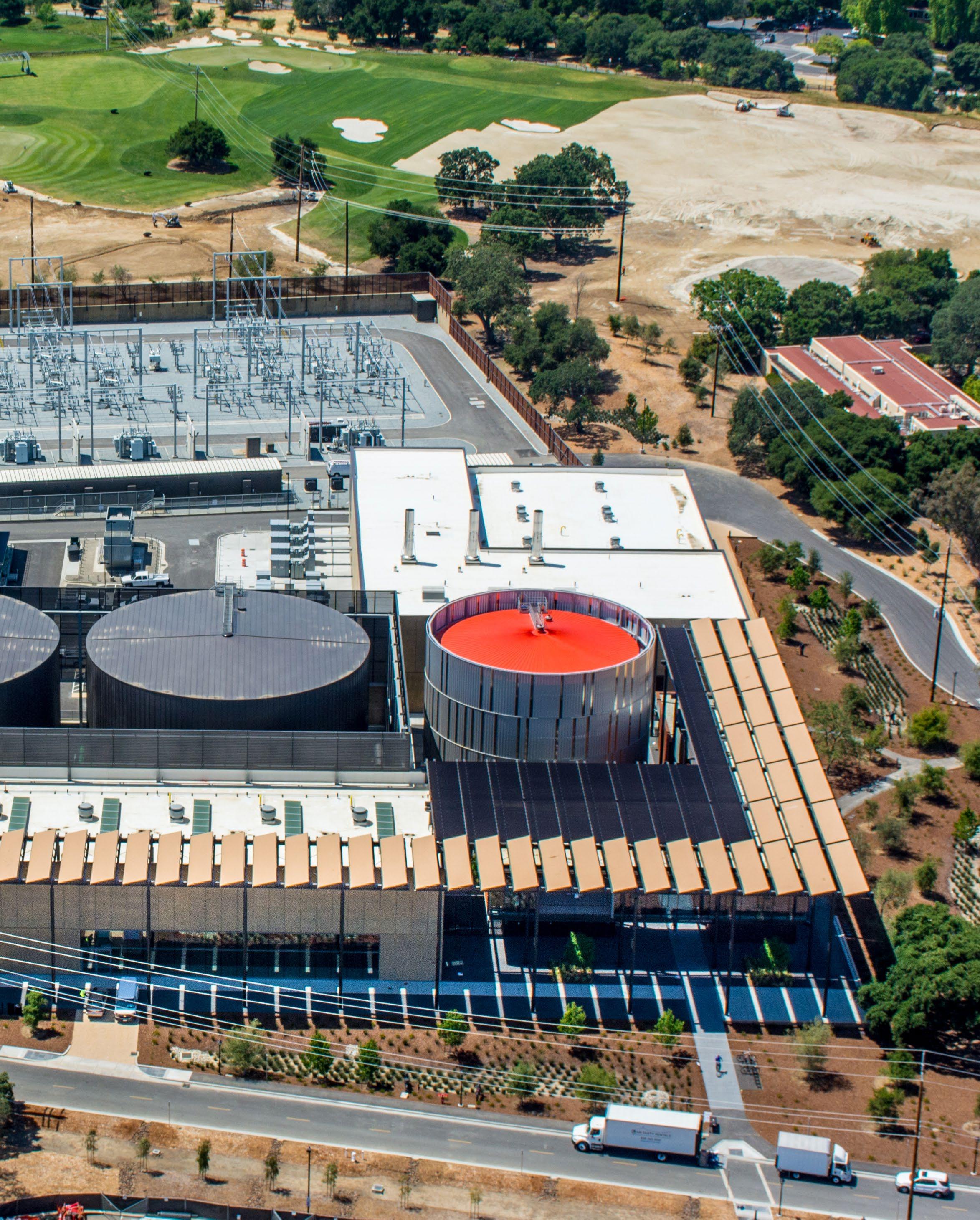
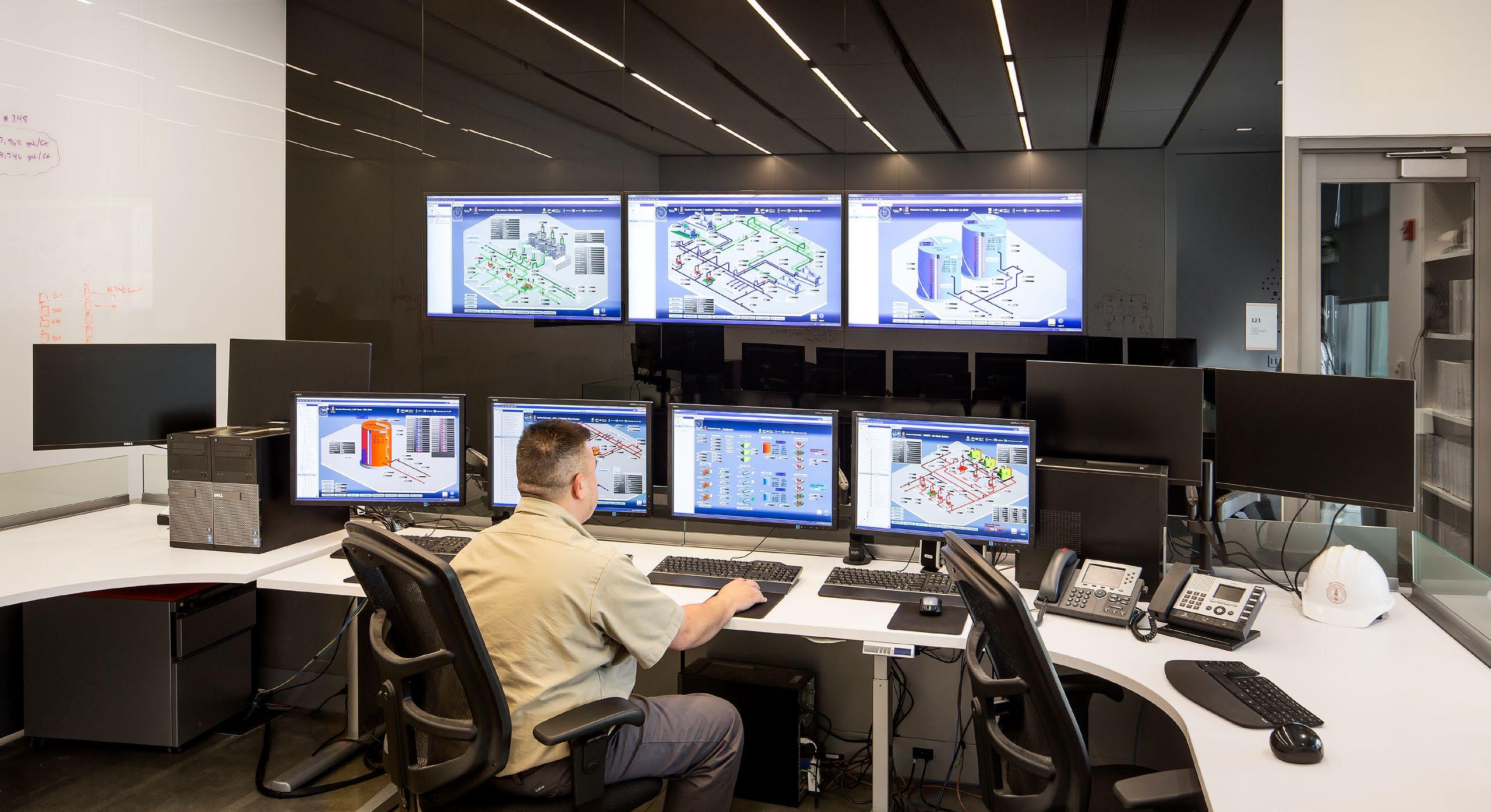
SESI combines an offsite, dedicated solar farm producing 68 megawatts of clean renewable electricity via 150,000 high-efficiency photovoltaic panels; conversion of the heat supply of all buildings from steam to hot water; and an innovative heat recovery loop that captures nearly two-thirds of waste heat generated by the campus cooling system to produce hot water for the heating system. At its heart is a new Central Energy Facility that embodies the latest technological advances in heat recovery. Heated and chilled water is stored in three massive water tanks totaling 12 million gallons. A patented technology developed by Stanford continuously monitors the plant’s equipment, predicts campus energy loads, grid prices and weather, steering the system to optimal efficiency. The automated software also reviews its own performance.
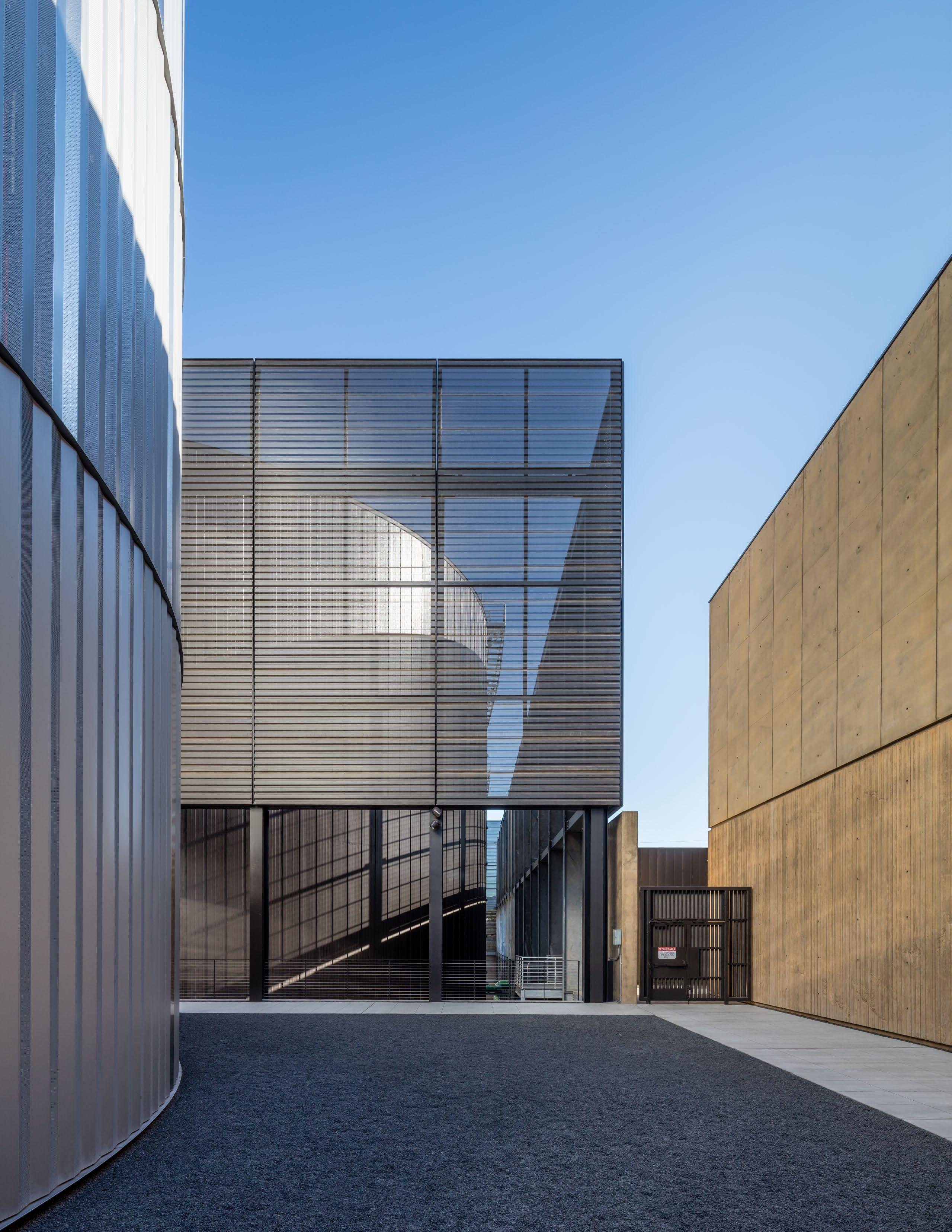
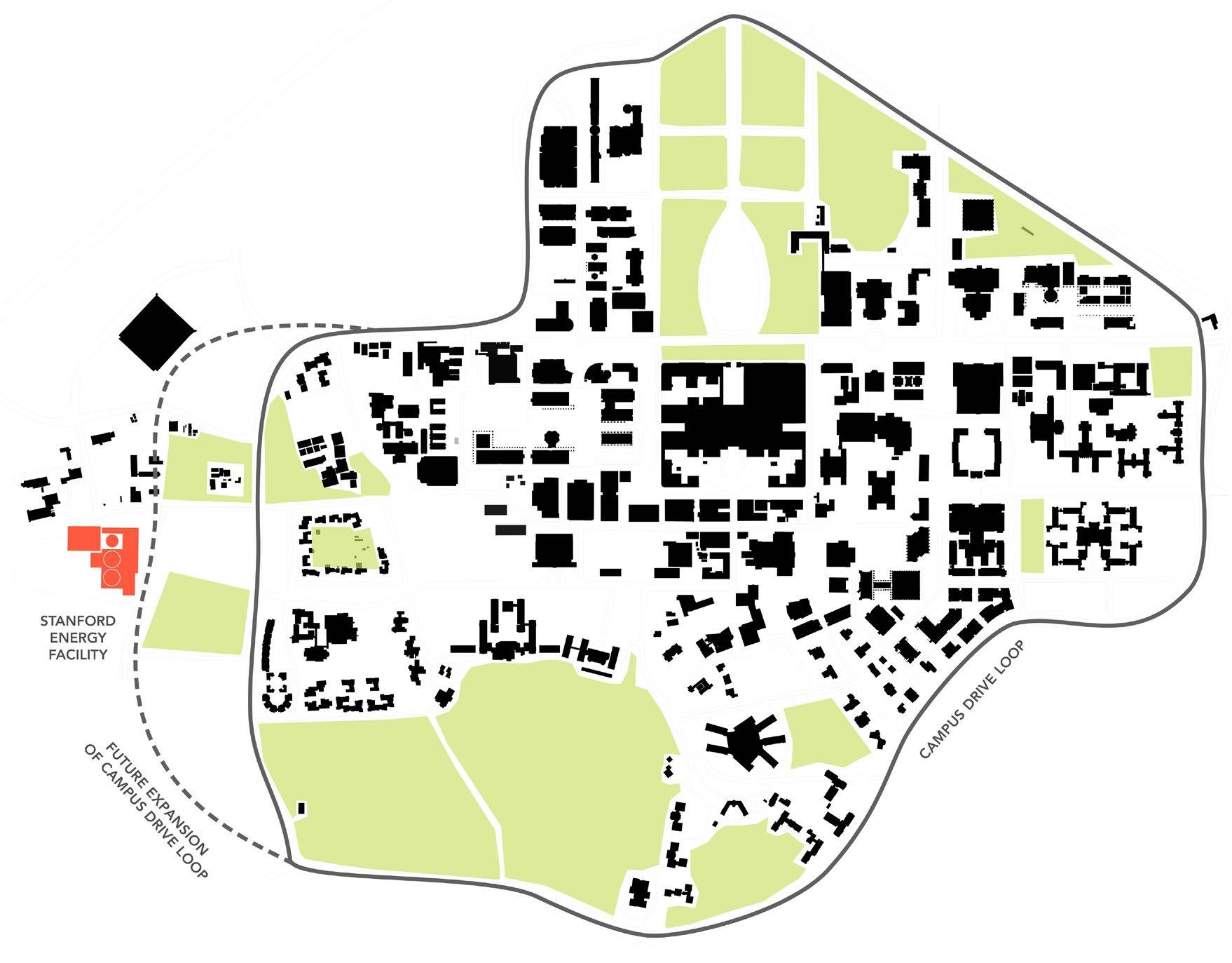
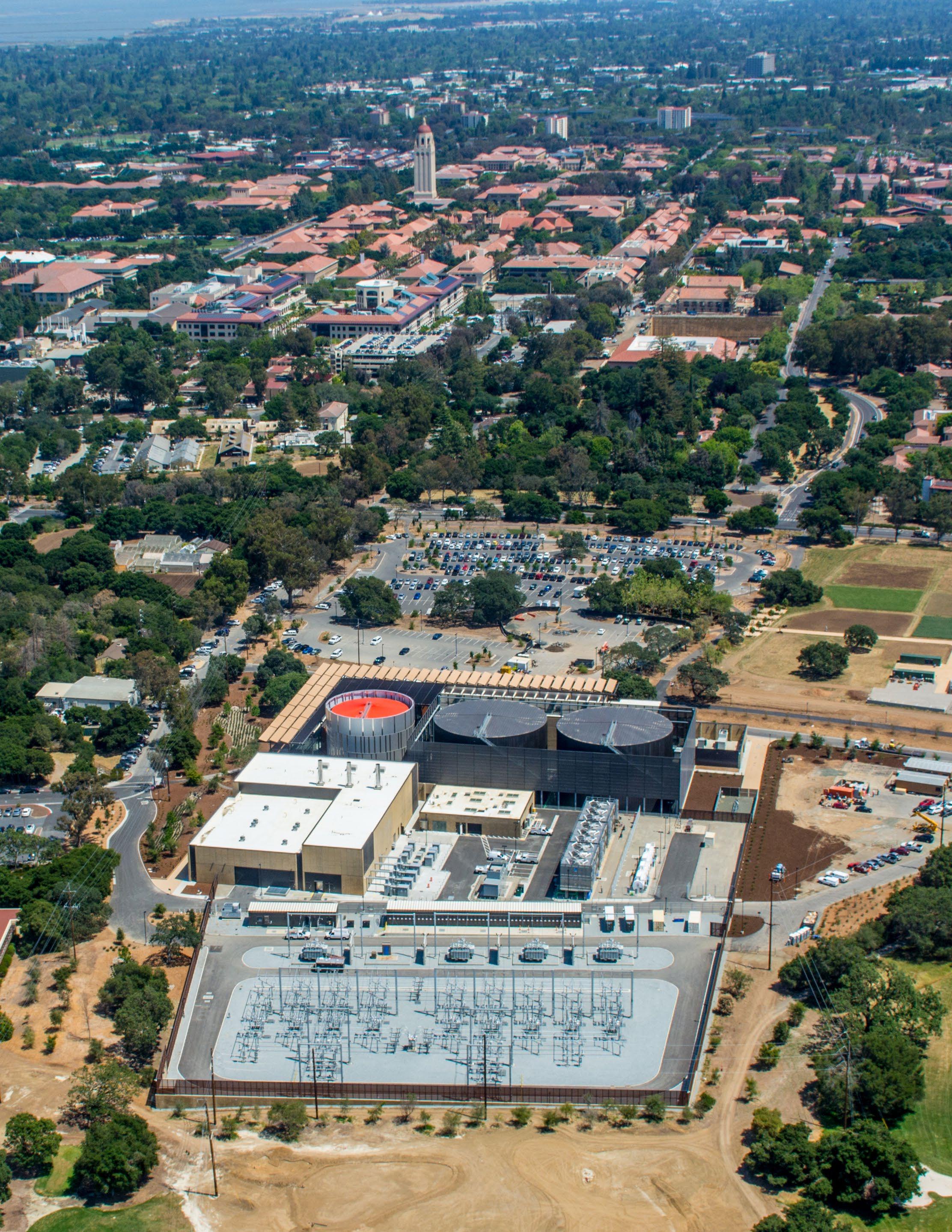
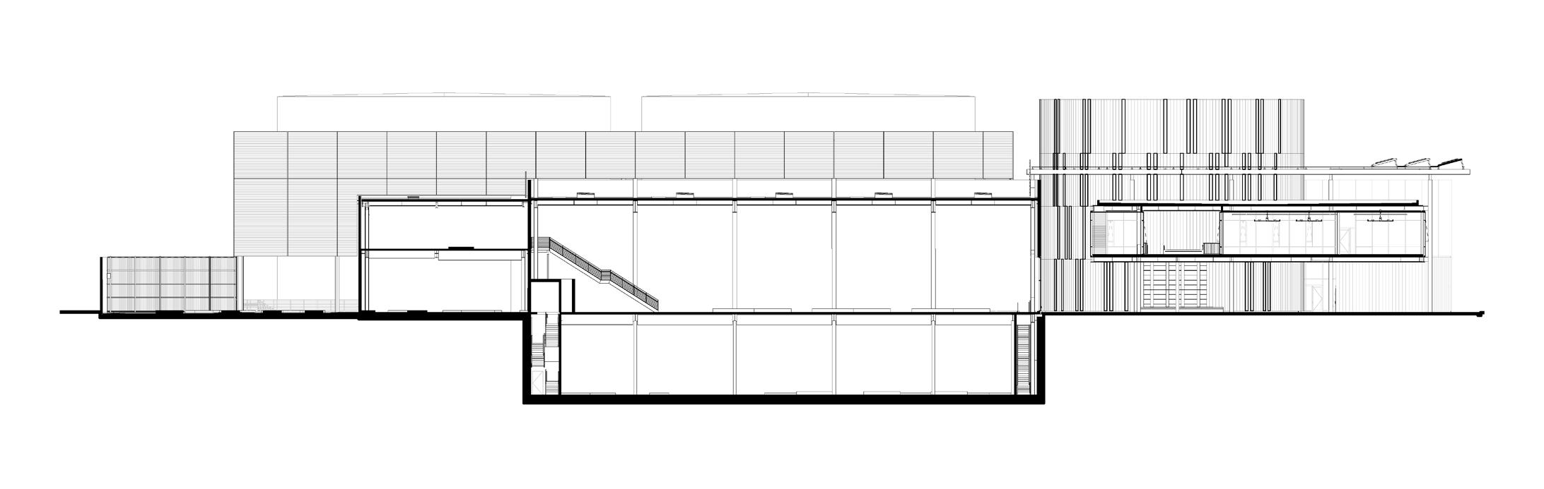
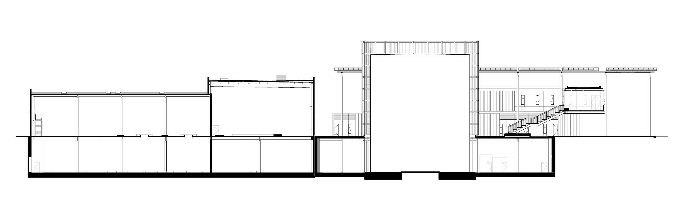
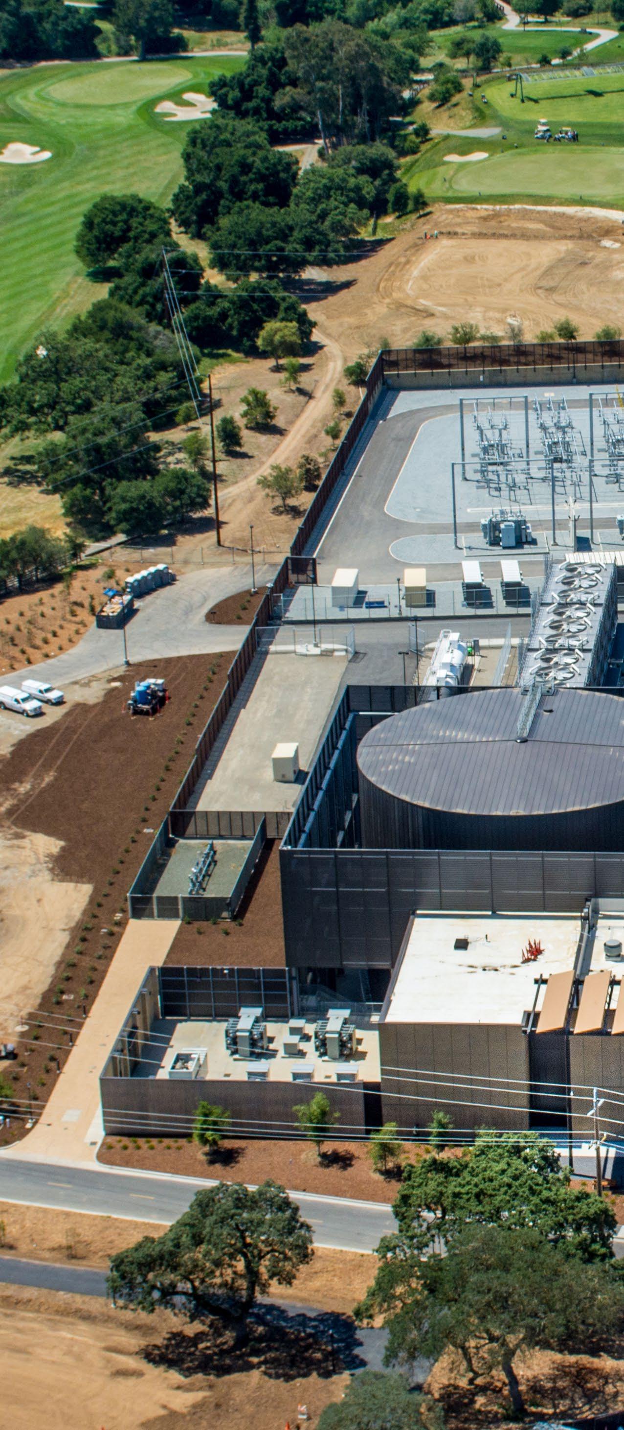
The 125,614 SF Central Energy Facility is located on the west side of the central campus, just outside the campus core. Its siting respects Olmstead’s original axial campus plan and functions to align the University’s founding and future quads. The energy complex is comprised of five distinct components: an Entry Court and Administrative/Teaching Facility, which serves as the knuckle between two major plant buildings; the Heat Recovery Chiller (HRC) Plant with its two large cold water storage tanks; the California State Office of Health Planning and Development (OSHPD) Plant; a service yard; and a new campuswide, main electrical substation. The massing and arrangement of the various components minimize the overall facility’s impact, with additional visual shielding provided by elegant metal screens. The main entry is on the prominent eastern edge, facing the central campus, while the electrical substation is located on the western edge to minimize its visual presence.
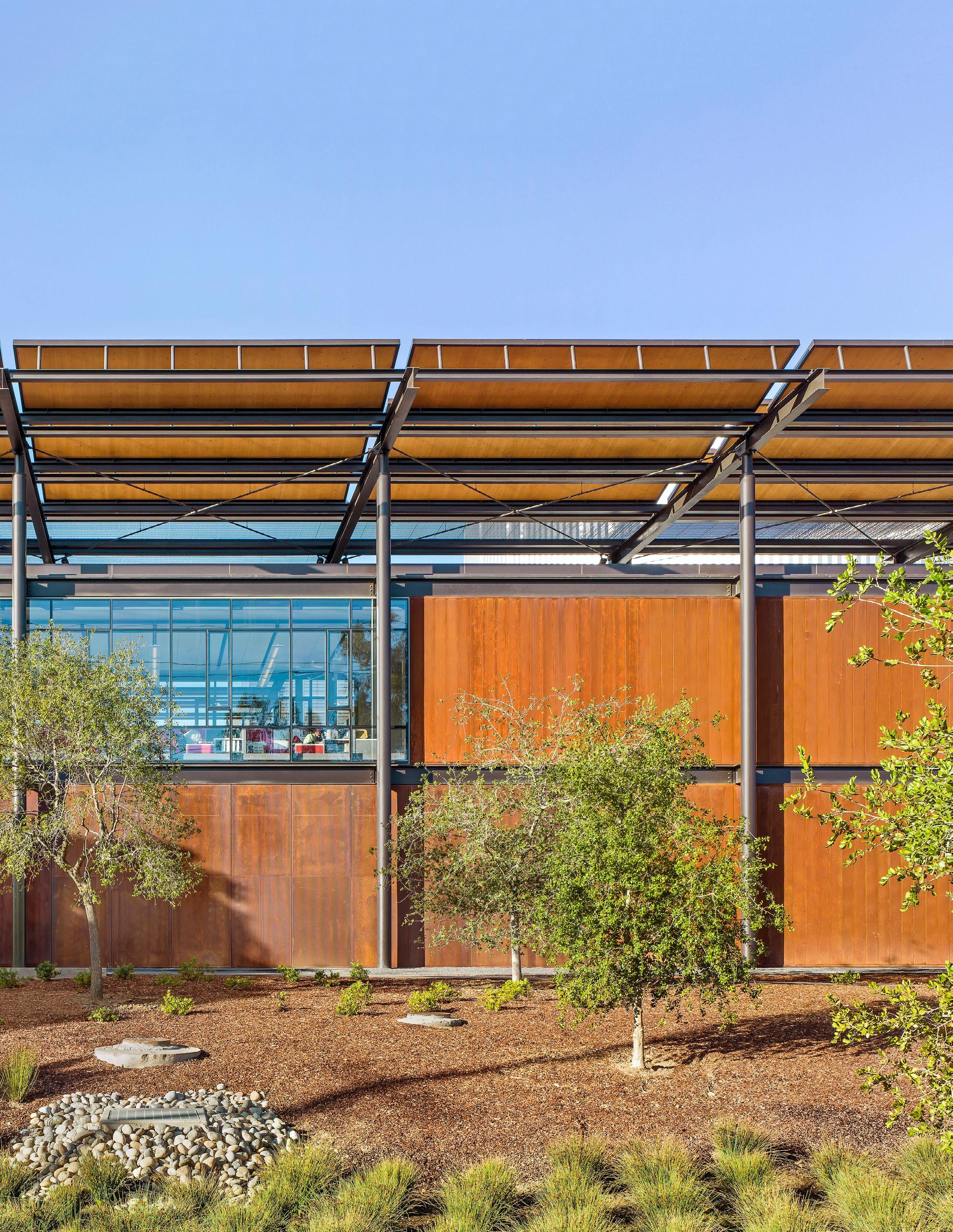
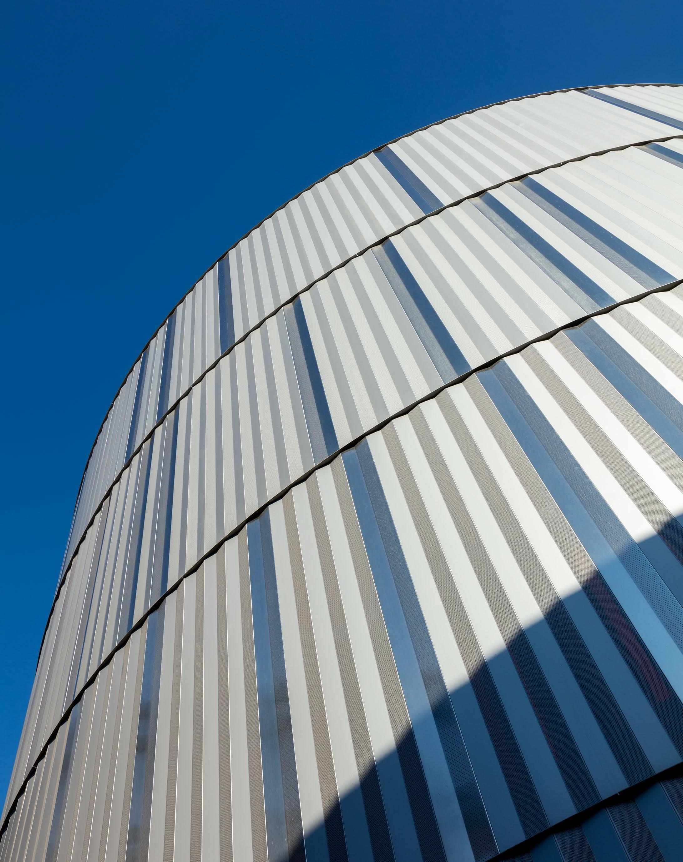
The overall architectural expression is one of lightness, transparency and sustainability to express the facility’s purpose. The Central Energy Facility’s materiality takes its cues from Stanford’s rich collection of historical and contemporary buildings. Stanford’s classic limestone buildings are represented by integrally-colored, board-formed concrete, while weathered CorTen steel accents suggest the terra-cotta tile roofs. Extensive glazing, dark steel columns and polished aluminum establish a contemporary vernacular, while reclaimed wood soffits in the arcades add warmth.
The design team took inspiration from the physiology of the human body, and specifically the cardiovascular system — which is driven by the heart and lungs constantly beating and respiring to circulate energy throughout the body.
The Central Energy Facility is located on the west side of the central campus, just outside the campus core. Its siting respects Olmstead’s original axial campus plan and functions to align the University’s founding and future quads. The main entry is on the prominent eastern edge, facing the central campus, and will gain more prominence as the University extends the Campus Drive Loop.
 PHOTOGRAPHER © Steve Proehl
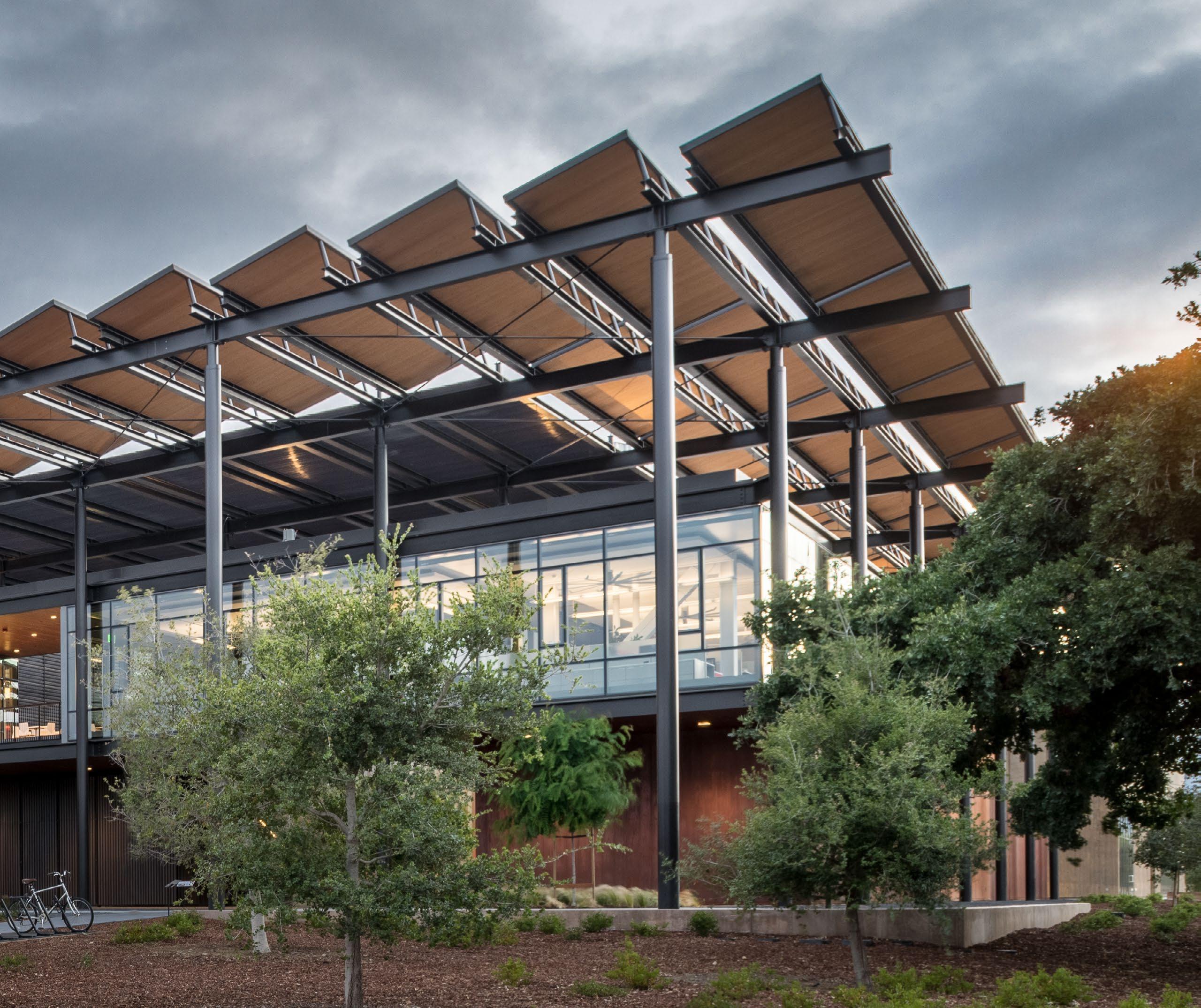
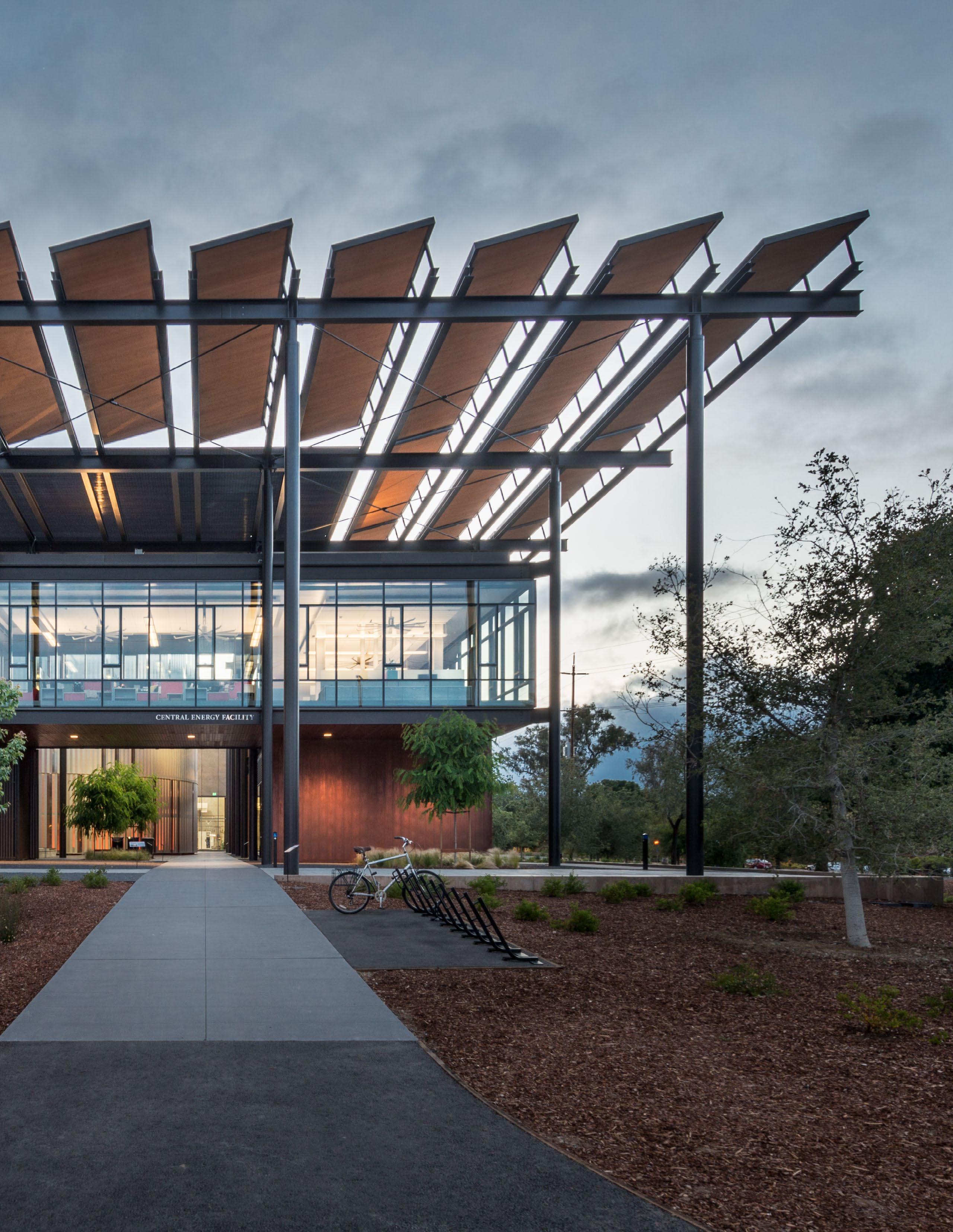
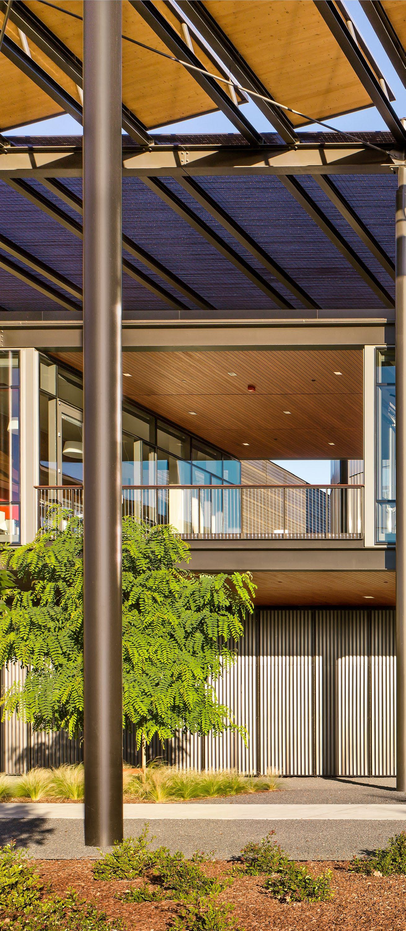
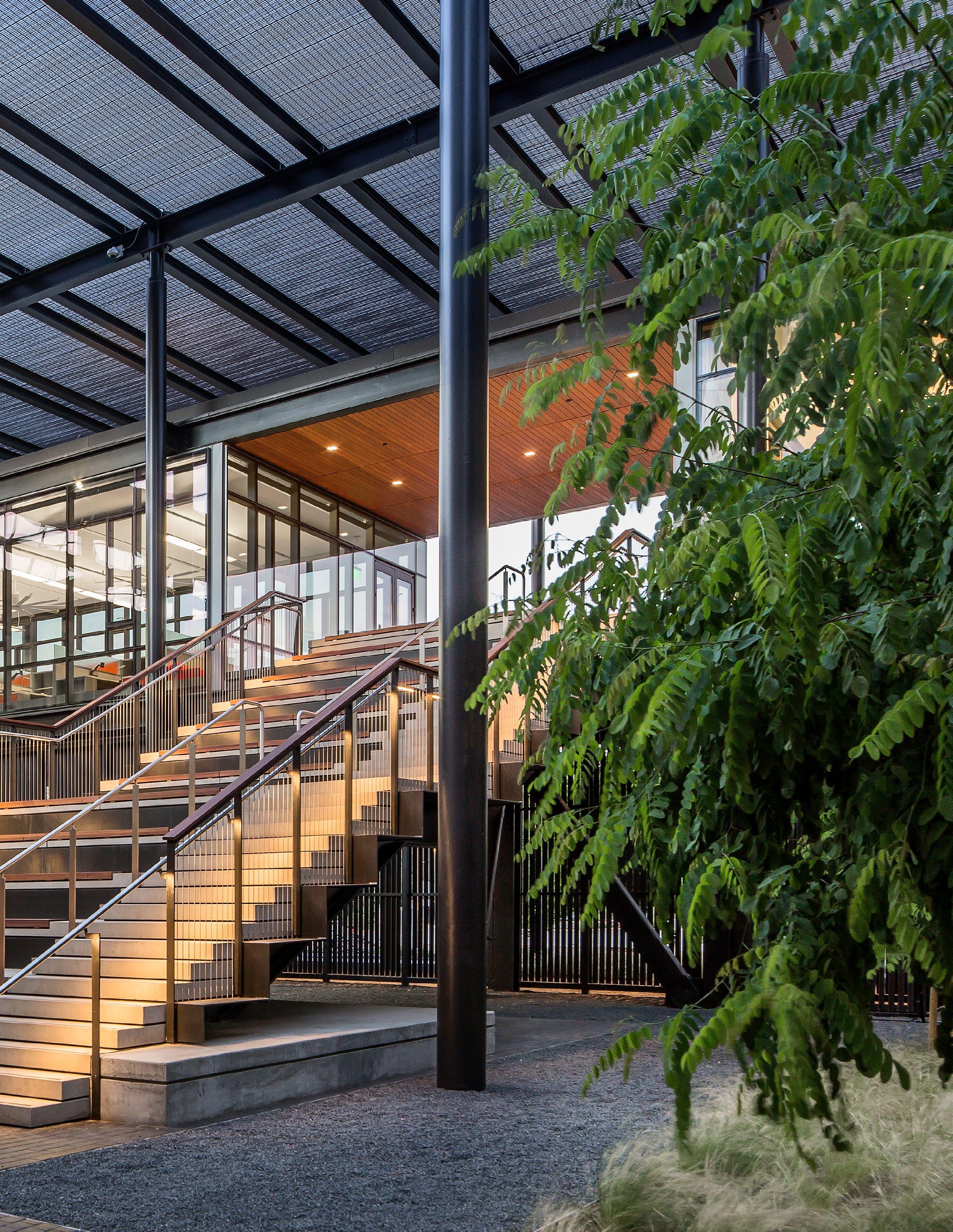
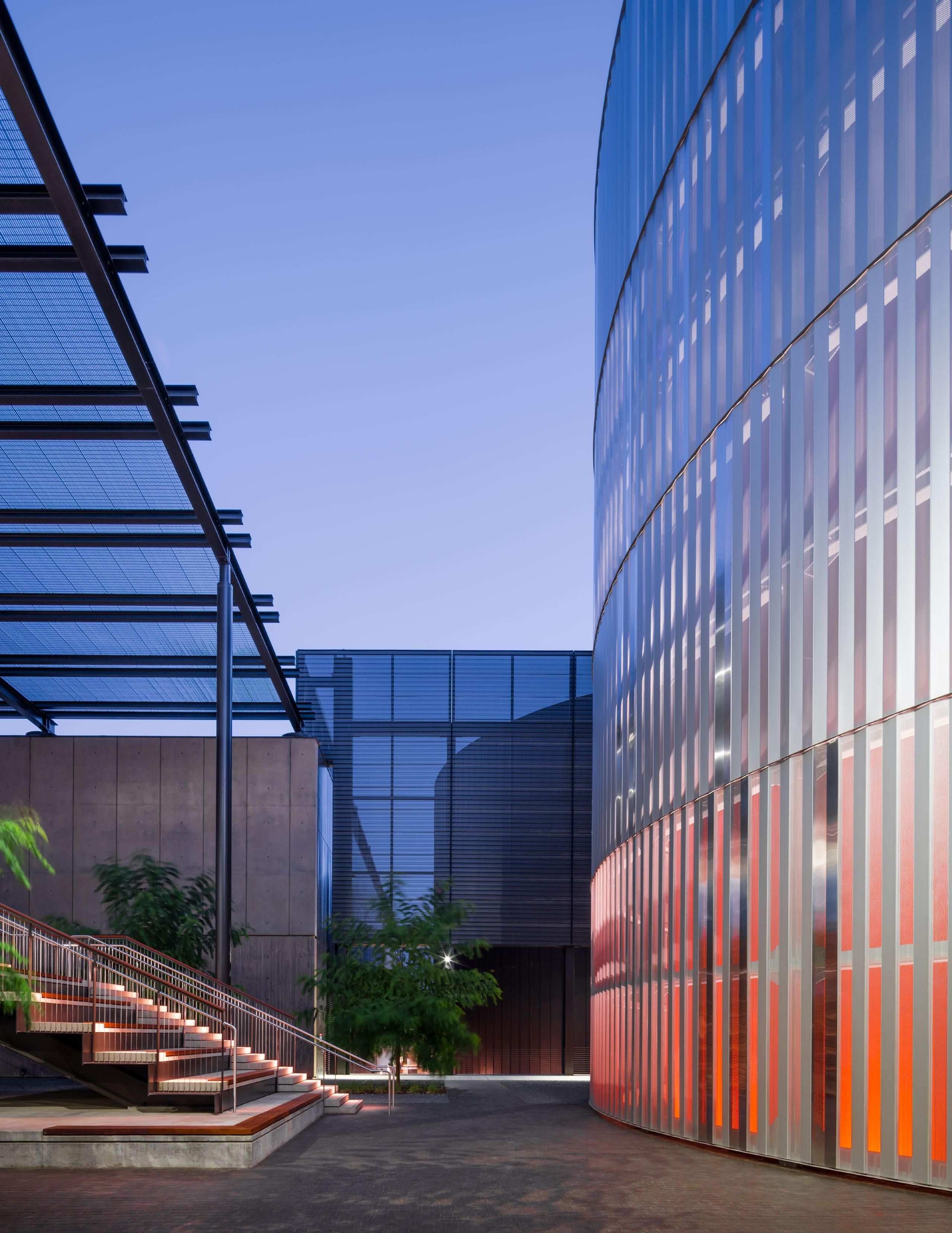
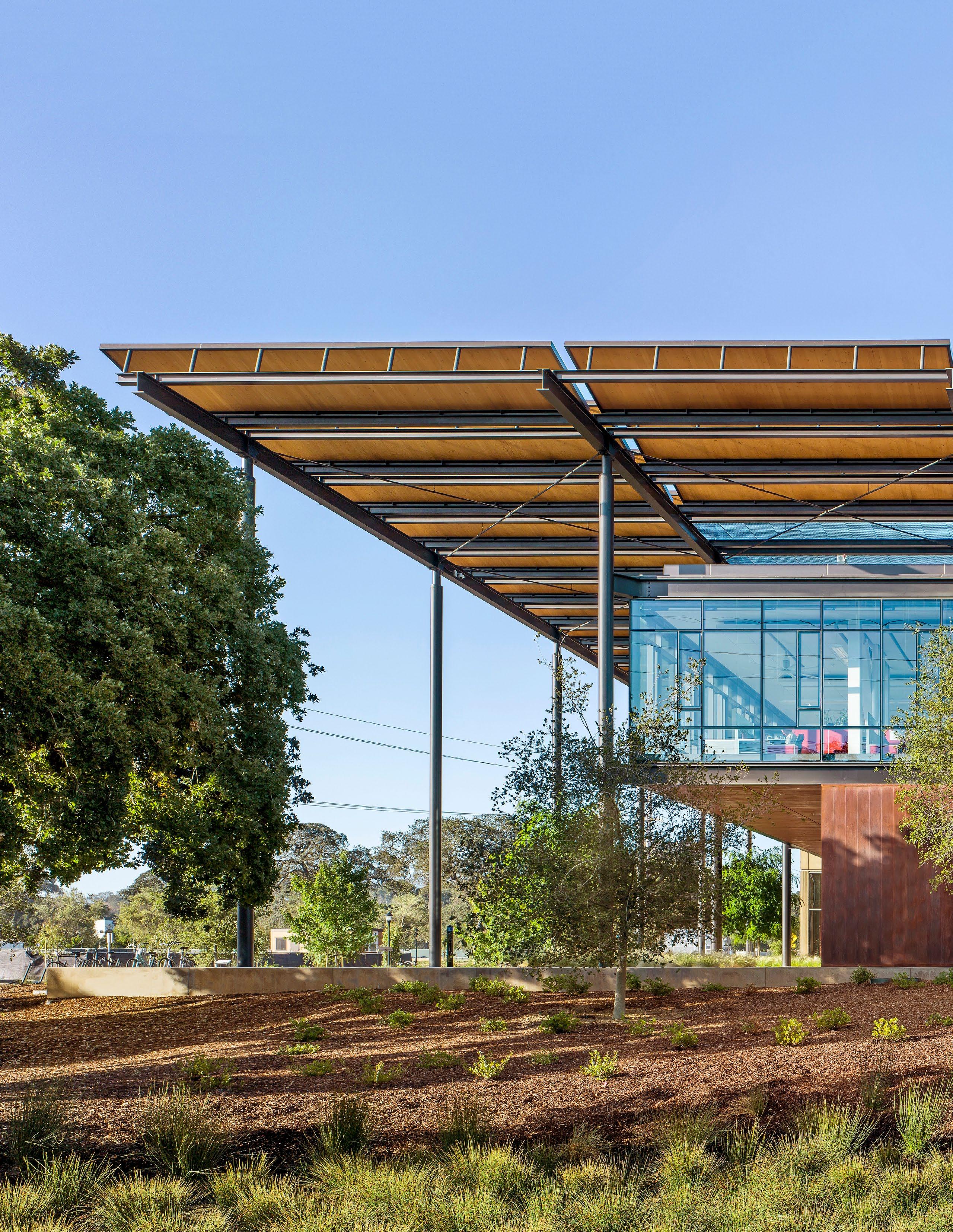
The Entry Court and Administrative/Teaching Facility set the architectural tone for the complex. The Entry Court welcomes faculty, students and staff, as well as visitors, into the Administrative/Teaching Facility. The entrance features an expansive photovoltaic (PV) trellis that provides shade and cover, and more electricity than needed to power the net-positive-energy Administrative/Teaching Facility.
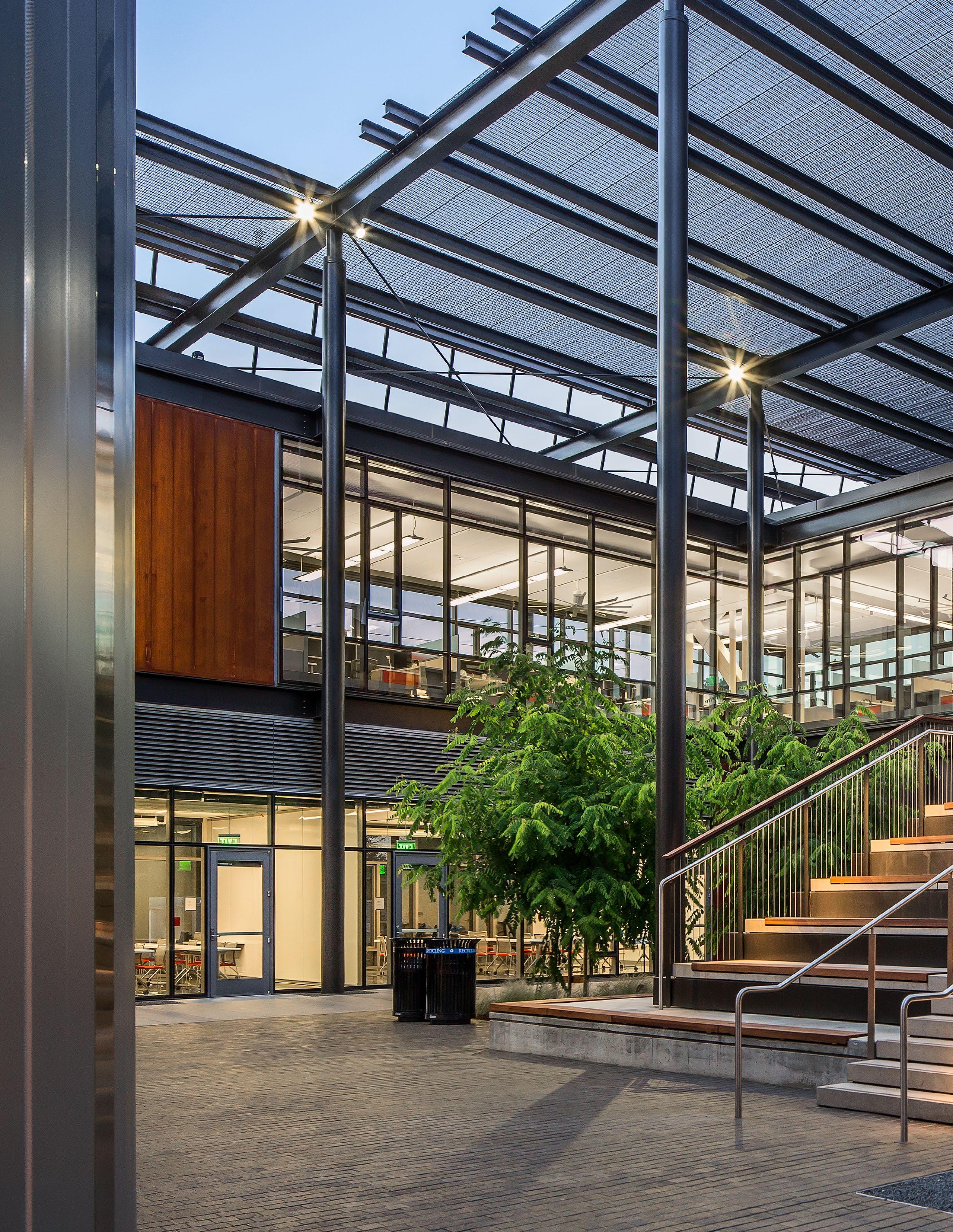
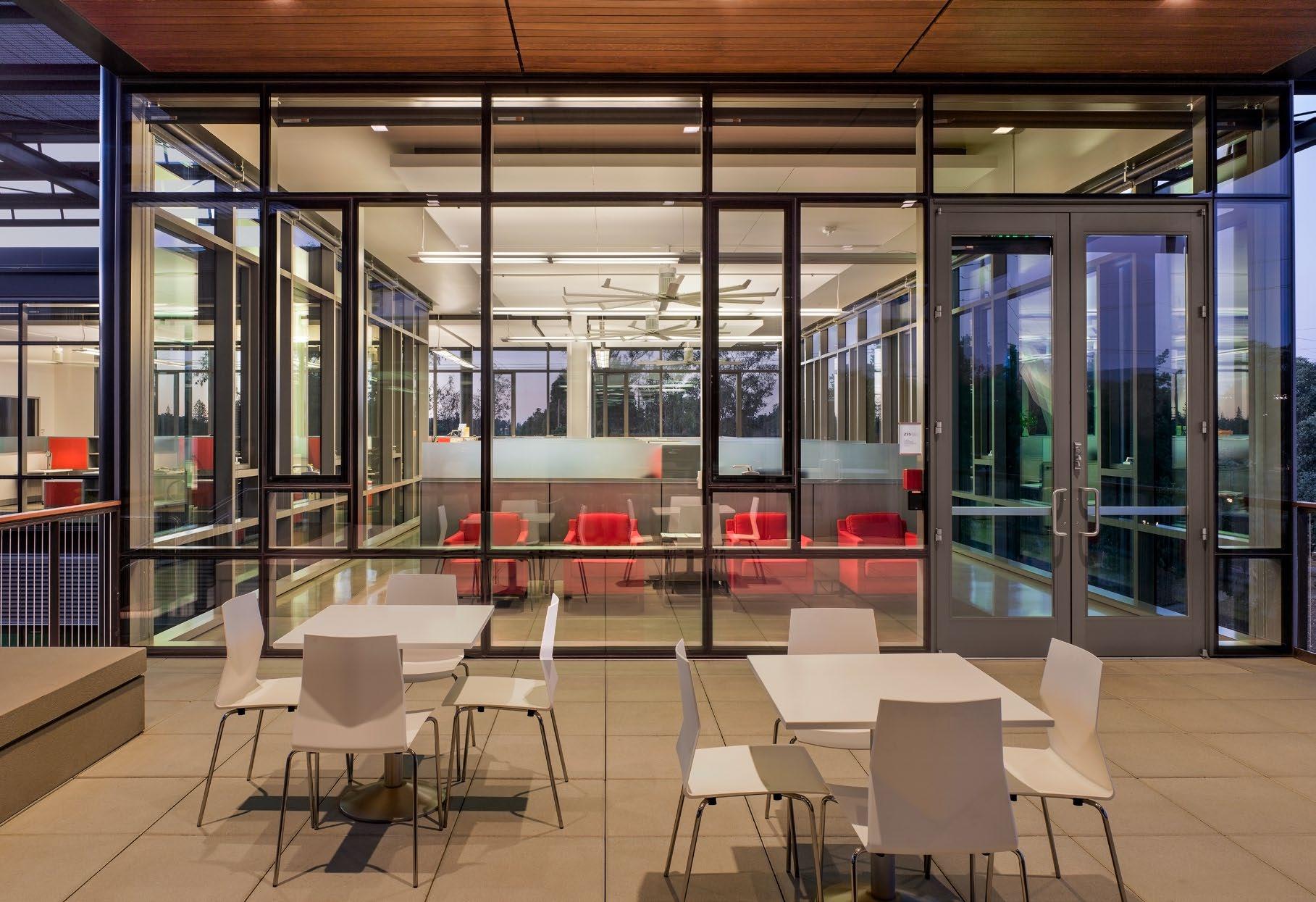
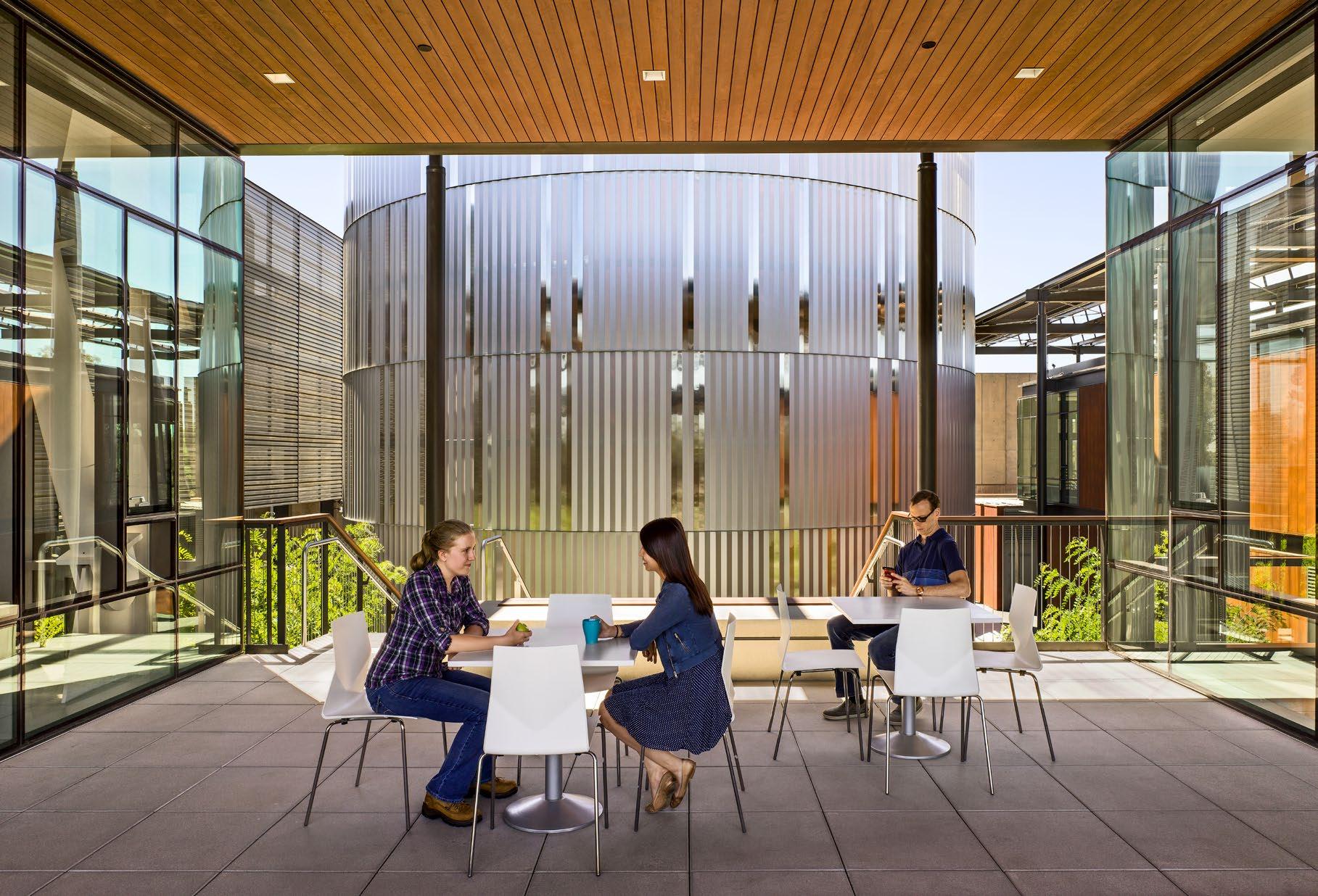
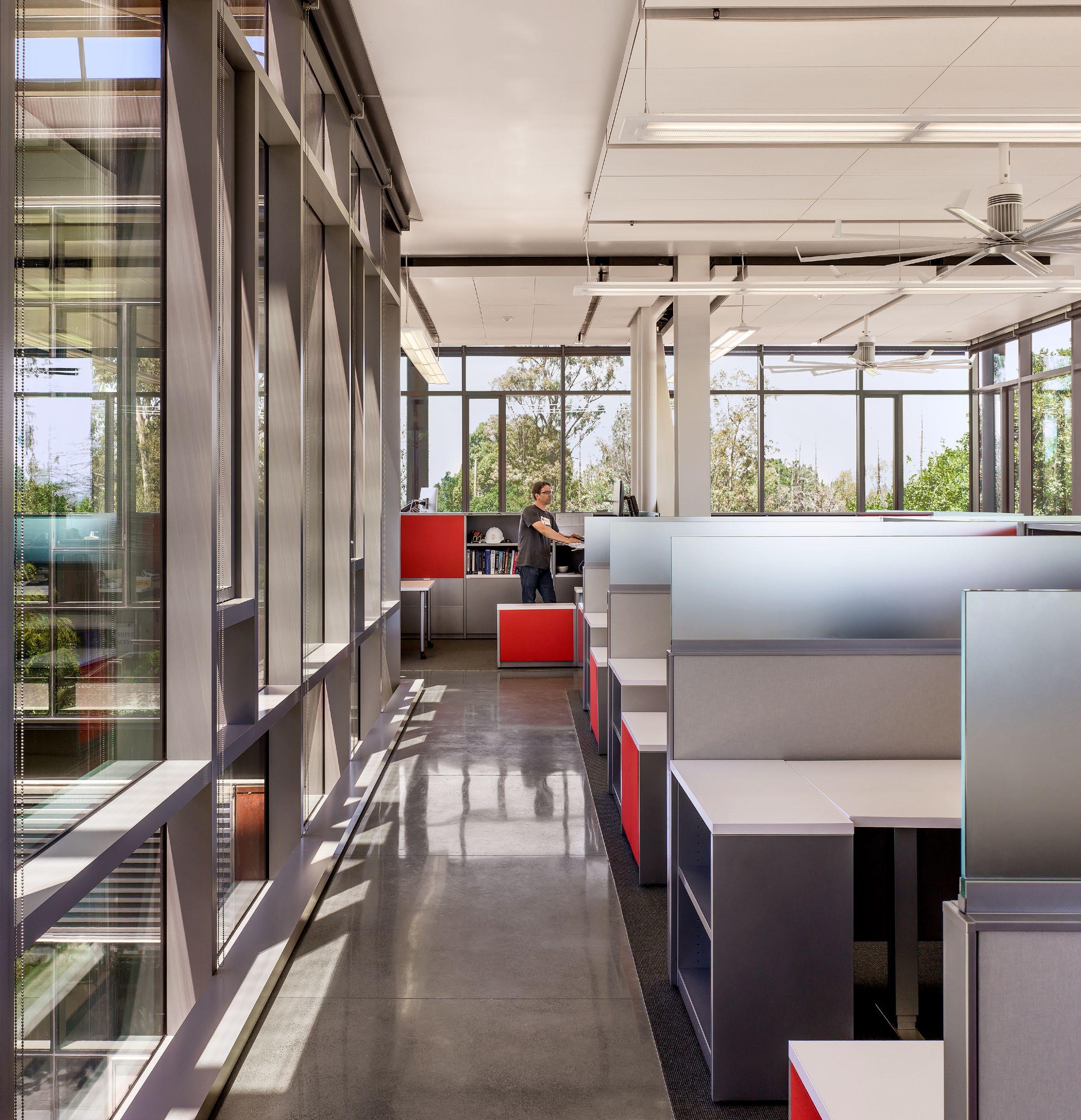
The exterior of the Administrative/Teaching Facility is predominantly curtainwall, maximizing natural light for the interior work stations and classrooms, while animating the facility from the outside. Glass-enclosed office spaces and an outdoor, multi-use room float above the entrance, providing views out to central campus as well as into the hub of the facility, where a paved and landscaped courtyard displays the primary thermal energy storage tank, painted “Stanford Red.” At night, lights directed through slender perforated steel columns transform the facility’s centerpiece hot water tank into a red, glowing beacon that serves as the “heart of the facility.”
The courtyard within the Administrative/Teaching Facility provides a gathering space for visitors and tour groups, and is protected from the elements by the overhead canopy. A grand staircase serves as the entry to the second floor offices, outdoor room, and staff kitchen and lounge, and is also utilized as theater seating for tours and lectures, with the thermal storage tank as the stage backdrop. A large conference room, located on the first floor, offers flexible design for additional classroom space.
While the PV trellis provides more than enough energy for the building, the net-positive-energy facility also incorporates operable windows and natural ventilation, maximum daylighting, rainwater harvesting for gray water use, and a radiant slab with exposed chilled beams for heating and cooling. The ceilings are filled with “phase-change material” that, depending on the temperature, changes from solid to liquid and smooths out the thermal peaks, thereby helping to maintain a comfortable interior temperature .
PHOTOGRAPHER © Robert Canfield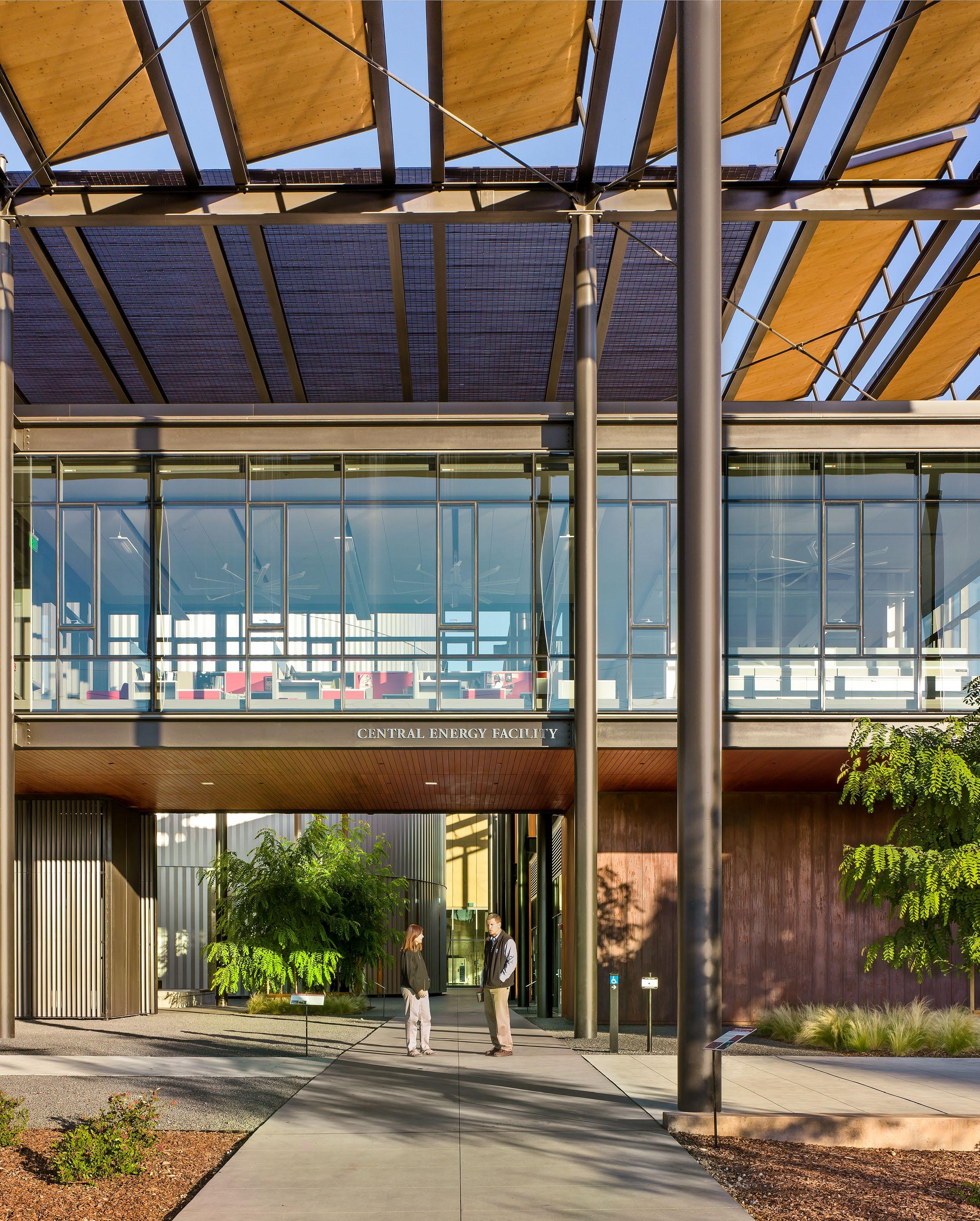
 PHOTOGRAPHER © Robert Canfield

 PHOTOGRAPHER © Robert Canfield
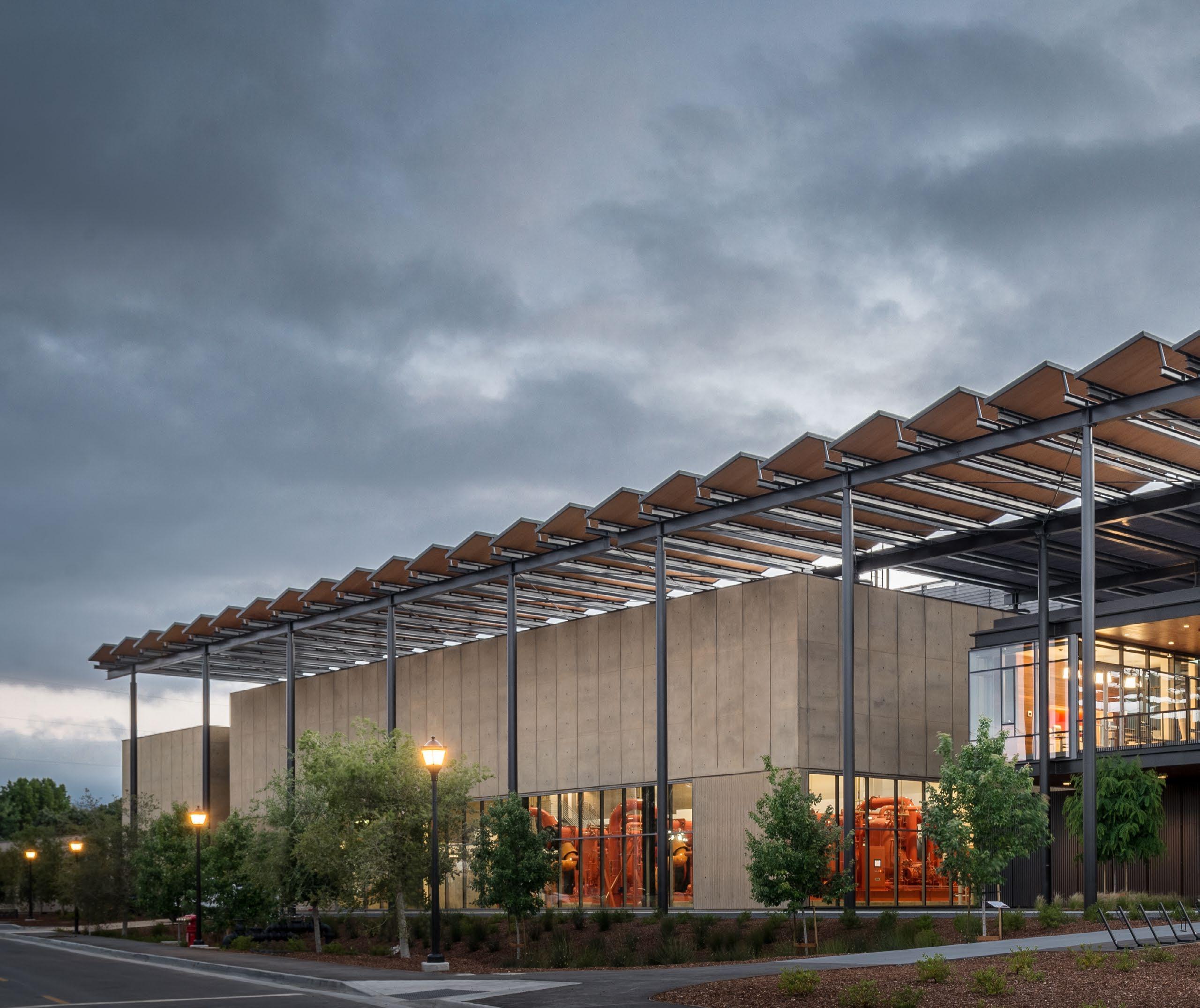
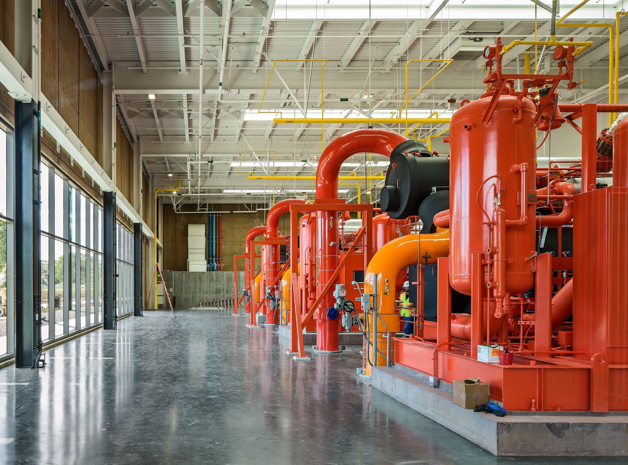
The Heat Recovery Plant (HRP), the key player in this ultra-efficient energy loop system, sits along the prominent eastern edge of the complex, immediately south of the Administrative/Teaching Facility, and shares the overhead PV trellis as an organizing and unifying architectural element. Its lighter, limestone-colored concrete exterior distinguishes the two buildings, while minimizing the plant’s mass as it extends farther east towards the road and campus.
The architectural palette of exposed steel columns and integrally-colored concrete provides a neutral backdrop to the vibrant mechanical and electrical equipment on display. Natural daylight illuminates the plant through a series of skylights and curtainwall openings. The two large, cold water thermal storage tanks are part of the massing of the plant, and are visually shielded by a perforated metal screen wall that extends beyond the height of the plant itself.
The Central Energy Facility (CEF) also powers Stanford’s School of Medicine and the Lucille Packard Children’s Hospital. As healthcare institutions, they fall under the State of California’s OSHPD jurisdiction, requiring the CEF to include enough OSHPD certified equipment to serve hospital loads. Although both the HRP and Cooling & Heating Plant (CHP) work together to serve the combined loads of both the main campus and hospitals, the OSHPD requirement was accomplished by physically separating the CHP from the rest of the energy complex and certifying it under OSHPD. The plant houses three boilers with room for future expansion of two boilers; six chillers; and a main electrical room. The glazed east wall of the boiler area also serves as a visual connection to the Entry Court and the Administrative/Teaching Facility, allowing the equipment to be showcased as part of the overall storytelling of innovative energy technology used throughout the complex. The CHP follows the same minimal palette of the HRP to highlight the mechanical and electrical components.
The electrical substation is located on the western edge of the site to minimize the visual impact from central campus, and a landscaped berm screens it from the adjacent golf course. The substation brings electricity from the Stanford Solar Generating Station (SSGS), developed under a partnership between Stanford and Sun Power, as well as other grid generating sources to power the CEF and other campus buildings. The SSGS will provide 50% of Stanford’s electricity; an on campus PV project will provide 3%; and the remaining grid purchases will provide another 12% of renewables. This power mix provides 65% clean electricity to Stanford’s buildings.
 PHOTOGRAPHER © Robert Canfield
The cornerstone of SESI is recovering waste heat from the campus direct chilled water system to meet building heating and hot water needs. This opportunity was discovered upon review of hourly energy production data as the University began exploring options to replace its aging gas fired cogeneration plant scheduled for decommissioning in 2015. With cooling occurring mostly in summer and heating in winter, the opportunity for heat recovery was assumed to be
modest until Stanford engineers compared the simultaneous delivery of heating and cooling from the cogeneration plant over all hours of the year. This revealed a large overlap and a major new opportunity for efficiency and cost savings in energy production, as well as sustainability since a heat recovery system could be powered by renewable electricity instead of natural gas.
Heat Recovery Potential = 80% of Stanford University’s heating demands can be met with waste heat already being removed by the campus cooling system.
Evaporative Cooling
Heat Recovery Potential
Gas Heating
Transforming the campus-wide distribution system was a massive endeavor. It required converting 22 miles of steam pipes to hotwater pipelines across the entire 8,000-acre campus, in addition to retrofitting 155 buildings. Completed in less than two and a half years, the work was carefully phased to ensure that on-going academic and medical center activities would not be disrupted, and that the heating and cooling service would always be available to the two major hospitals and nearly 200 academic buildings.
 PHOTOGRAPHER © Robert Canfield