
Content
About Manual
Th is m an u al co n tain s d etail s o f th e p r o d u ct, in fo rm atio n o n its o p er atio n an d m ain ten an ce, an d o th er h el p fu l tip s fo r o w n er s. Read it carefu l l y an d fam iliarize y o u rself with th e Yotobike Yotobike b efo re u sin g it to en su re safe u se, red u ce risk o f d am ag e an d p rem atu re wear, an d p rev en t accid en ts.
Be su r e to r etain th is m an u al as y o u r co n v en ien t in fo rm atio n so u rce.
Th is m an u al co n tain s m an y W arn in g s an d Cau tio n s co n cern in g safe o p er atio n , an d co n seq u en ces if p r o p er set u p , o p er atio n an d m ain tenance g u id el in es are n o t fo ll o wed . A ll in fo rm atio n in th is m an u al sh o u ld b e carefu lly r ev iew ed .
The safety grade color of Caution is orange, and if not avoided, may result in moderate or serious injury.
Users should also pay special attention to info-rma tion marked in this manual beginning with “NOTI CE ”
The safety grade color of W arning is red, and if not avoided will likely result in serious injury or death.
Because it is impossible to anticipate every situation or condition which can occur while riding, this manual makes no represen tations about the safe use of our bicycles under all conditions. There are risks associated with the use of any bicycle which cannot be predicted or avoided, and which are the sole responsibility of the rider. You should keep this manual, along with any other documents that were included with your bicycle, for future reference , however all *The recommended minimum rider age is 1 6 and over , and the maximum rider age is 7 0 and under. Any rider who cannot sit comforta adjustment of your Yotobike requires special tools and skills, and it is recommended that this be performed by a trained bicycle mechanic if possible. content in this manual is subject to change or withdrawal without notice. Visit Yotobike. com to download the latest version. A ssembly and fi rst not attempt to ride it.
1
Bike Specification
Rear Brake
Motor
Rear Derailleur
Saddle Battery Controller
Rear Shock
Head Tube
LED Headlight
Front Suspension Fork / Front Shock
Front Brake

2

A - Total Length 8 2 . 6 I n c h B - Handlebar Height 4 6 . 5 I n c h C - Wheelbase 5 5 . 1 I n c h D - Min Seat Height 3 2 I n c h E - Max Seat Height 3 7 I n c h F - Chain Stay Length 2 0 . 8 I n c h G - Standover Height 3 1 . 4 I n c h H - Top Tube Length 2 4 I n c h I - Wheel Diameter 2 8 . 7 I n c h J - Head Tube Length 6 . 3 I n c h K - Handlebar Length 2 7 . 6 I n c h I 3
Battery Range
Tires Brake lever
Taillight
Freewheel Brake Chain Stem
Crankset
Gearing
6 0 - 8 0
48V 20Ah Battery with SamsungCells miles
1 0 0 0 W brushless gear hub motor
4 0 0 lbs
5 '3 " ~ 6' 5 "
2 6 " x 4 . 8 " CST fat tires
Aluminum alloy comfort grip levers with motor cutoff switch
Battery powered bike light
Shimano 7 - speed gear shift system
1 8 0 mm Hydraulic Brakes
Charger Controller
US standard 3 . 0 A smart charger
4 8 V/ 2 5 A
LCD display with USB charging
70 lbs
0 ~ 5 level pedal assist
Thumb throttle
Alloy front suspension fork with lockout and a d justment
Alloy pedal with reflectors
Frame
6 0 6 1 aluminum frame
4 8 V LED light
KMC chain SR saddle
Promax MA- 4 0 0 SSABK
1 7 0 mm forged alloy
Shimano- 1 4 - 2 8 T BROWN/ BK
φ 3 1 . 8 mm* 3 0 0 mm Alloy Seatpost
Heavy- duty aluminum
1 3 gauge front / 1 2 gauge rear
Motor Total Payload Capacity Rider Heights
Display
Intelligent
4
Weight Pedal Assist
Throttle Front Fork Pedal Bike
Headlight Saddle Seatpost Kickstand Spokes
Bike Assembly Guide
Preparation Checklist
Headligh t
Power cable
Trans fo r m er
Quick- release skewer Pedals Hex wrench
NOTICE: 1 . Pleasekeep the original packaging for at least 1 5 days !
2 . Before assembling your bike, it’ s recommended to remove the battery for the reasons outlined below:
• Determine if there’ s battery drain or damage during shipping.
• Reduce the weight of the ebike to make it easier to maneuver the bike while assembling
• Avoid battery damage during the assembly process
◆ 5
Recommended Torque Values
NOTICE: Using an impact driver to achieve the required torque is not recommended as it might cause damage We suggest you use the wrench set we provided and extra tools to manually adjust nuts and bolts.
Hardware Location Recommended Torque( NM) Handlebar 1 2 - 1 8 Stem 12 - 1 8 Saddle 1 2 - 1 8 Front W heel (for bikes with bolts on front wheel) 1 5 - 2 2 Rear wheel 3 0 - 3 8 Bottom Bracket Parts 3 0 - 5 0 Pedals 2 8 - 3 3 Disk Mounting Bolts 3 - 5 Disk Caliper Mount 6 - 8 Crank Bolts 3 2 - 3 6 Rear Derailleur Cable Pinch 3 - 5 Front Derailleur Clamp 3 - 6 Saddle Post Clamp 3 - 6
6
Front Fork Installation


7
Assembly Instructions
Handlebar Installation ( 4 mm Hex Wrench )
Step 1 : Loosen the bolts on your bike stem.
Step 2:
Step 3: Center your handlebars and rotate them to align to the marking pointed to in the below image. Tighten bolts to handlebar stem, but don’t tighten completely as you may want to further adjust the angle later to align more precisely. Test the positioning, and adjust the handlebar to your preferred angle. After determining the best position, completely tighten all the bolts on the stem.

NOTICE: In addition to angle, the height of the handlebar can be adjusted by adding or removing the headset sp acers if needed. For those without experience, we recommend having a professional make such adjustments for safety reasons.


◆
8
Fro n t w h eel
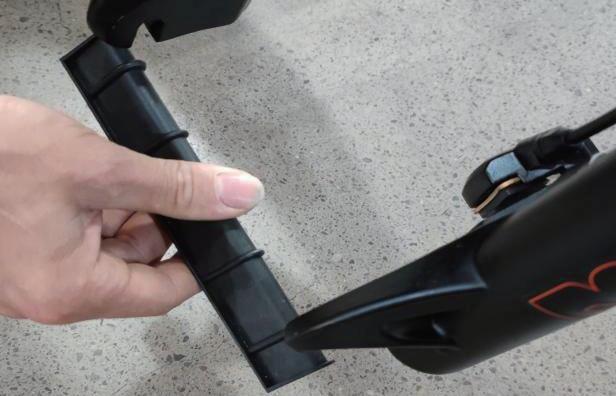
Step 1 : Take o u t th e b l ack g u ard b l o ck o f th e fro n t fo rk. Pu ll o u t th e red p ad , w h ich is u sed to p ro tect th e h y d rau lic b rake calip er.

Step 2 : Ro l l th e w h eel in b etw een th e fro n t fo rk. A lig n th e fo rk d ro p o u ts w ith th e axle o f th e w h eel h u b , m akin g su re th e d ro p o u ts are fu lly seated o n th e axle. A lso , en su re th e b rake ro to r is p ro p erly in serted in to th e calip er .


Step 3 : Prep are y o u r q u ick-release skew er fo r th e n ext step b y rem o v in g th e th u m b n u t an d o n e o f th e co n e sp rin g s
◆
9
S tep 4 : I nstall quick-release strings from the side without brake discs, inserting the quick- release skewer through the hub, and then replacing the second cone spring on the other side. E nsure both springs are pointed narrow- side- in towards the wheel hub.

S tep 5 : Tighten the thumb nut until the quick-release lever is held in line with the axle, and then use your palm of your hand to close the quick-release lever


W A RN
Do not pull the brake lever without hav ing either the red pad or the brake disc inserted, as this will damage the hydraulic brake caliper.
10
I N G:
S tep 6 : I nfl ate the tires and make sure they have suffi cient pressure forriding comfort and safety, not exceeding the limit specifi ed on the sidewall.
S tep 7 : R otate the front wheel. Make sure to fully close the quick release skewer lever on the front wheel and check the wheel balance in Pedal Only Mode. I f notice the riding is imbalanced or the rotation of the front wheel makes noise, it means the bolts were not completely tightened or not aligned you horizontally.
11
Headlight ( 4 mm Hex Wrench & 1 0 mm Wrench)
Step 1 : Loosen the bolts on the fork brace. W hile holding the nut with a 1 0 mm wrench, unscrew the bolt with a 4 mm hex wrench.
Step 2 : Align the bolt holes of both your front light and the front fender together with the hole on the fork brace, then reinsert thebolt through all holes and tighten the bolt with a 1 0 mm wrench and a hex wrench Make sure the washer is directly under the bolt head


12
◆
ht pedal ( R) and the left can

ensure the pedal is going in have each pedal on the correct

13
WARNING: Overextending the seatpost can cause it to break or come off your bike, putting you at very high risk of serious injury or death. Avoid this danger by inserting your seatpost into the seat tube far enough that the minimum insertion point is no longer visible.


14
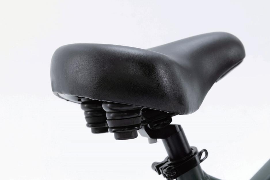
Adjust the Seat Angle:
Step 1:
Loosen the seat adjustment bolt beneath the seat. Move the seat backward or forward and tilt to adjust the angle within the limit markings etched on the seat rail. Do not exceed the limit markings, to ensure the safety of yourself and the bike.

Step 2:
Tighten the seat adjustment bolt. Ensure the top and bottom of the seat rail clamp are aligned, so that the seat adjustment bol t will clamp the seat rails together properly.
NOTICE: The seat angle has been preadjusted to factory safety standards. Please make note of original settings, and only adjust if nece ssary.
15
After Bike Assembly

Please write down the serial numbers found on the head tube, battery and motor on the inside front cover of this manual to faci litate failure reporting. Make sure each letter and number is correct.


16
Bike frame number
Battery serial number
◆
Motor serial number
Safety Checklist
Basic Step s
o Test front and rear brakes for proper function
o E nsure brake pads are not overworn and are correctly positioned in relation to rims
o Make sure brake control cables are lubricated, correctly adjusted and display no obvious wear
o Check that brake control levers are lubricated and tightly secured to handlebars.
o Infl ate tires to within recommended limits displayed on sidewalls
o Check for bulges or signs of excessive wear
o Clean tires to ensure tread is exposed
o E nsure rims run true and have no obvious wobbles or kinks.
o Check that all wheel spokes are tight and not broken.
o Check the wheel balance in P edal Only Mode If you notice the riding is imbalanced or the rotation of the front wheel makes noise, it means the bolts were not completely tightened or not aligned horizontally
o Check that chain is oiled, clean and runs smoothly.
o Use extra care in wet or dusty conditions
o S ecurely tighten pedals to cranks
o E nsure cranks are securely tightened and are not bent.
o Check that derailleur( s) are adjusted and functioning properyl.
o E nsure shift and brake levers are attached to handlebar securely.
o Check all brake and shift cables for proper lubrication
o E nsure hub motor is spinning smoothly and motor bearings are in good working order.
o Check that all power cables running to hub motor are secured and undamaged.
o Make sure hub motor axle bolts are secured and all torque arms and torque washers are in place
o E nsure battery is charged before use.
o Check for any visible damage to battery pack.
o Lock battery securely to frame.
17
s als Safety Ch eck Br a k e s W h eels an d Tire Ch a i n Cran ks an d Ped D e rail l e u r s M o to r D riv e Battery Pack
Safety Precautions
The following safety notes provide additional information on the safe operation of your Yotobike bike and should be closely reviewed. I mproper operation, or failure to confi rm correct installation, compatibility, and maintenance of any component or accessory may result in serious injury or death. ◆
•
Befo re Rid in g
All users must read and understand this manual before fi rst use. Additional manuals for components used on your bicycle may beprov ided and should also be ead before use.
E nsure you understand all instructions and safety notes/warnings.
F ollow the safety checklist before fi rst use and at regular use to ensure the bike is properly fastened and set up.
E nsure the bike fits you properly before first use. Check local rules and regulations before riding.
t is your responsibility to familiarize yourself with the laws and requirements of operation of this product in the area( s) where you ride. ◆
W h ile Rid in g
•
Always wear an approved bicycle helmet whenev er using this product and ensure that all helmet manufacturer instructions are us ed for fi t and care of your helmet. F ailure to wear a helmet when riding may result in serious injury or death.
Acceleration can be unexpectedly strong in pedal assist mode ( P edal Assist level 1-5) , as when you pedal the motor assist willsuddenly engage . Therefore, please pay careful attention when riding. W e suggest you use P edal Only Mode ( P edal Assist level 0) when you n eed to ride at a slow speed to cross roads, at intersections or when pedestrian traffic is present, in order to avoid accidents caused by sudden acceleration. .
Make sure you securely close the quick-release lever of the front wheel, checking the wheel balance in P edal Only Mode. I f you notice the riding feels imbalanced, or the rotation of the front wheel makes noise, it likely means the bolts were not completely tightened or didn’ t align horizontally in the center.
O ff-road riding requires close attention and specifi c skills, and presents variable conditions and hazards which accompany the conditions.
W ear appropriate safety gear and do not ride alone in remote areas.
18
• • • • r I
• • • •
Yotobike Use and Care
The following table of contents provides general guidance on Yotobike variable power assist settings and their effects on both range and performance
This content will apply broadly to most riders, but multiple factors will aff ect individual results including rider fi tness and weight, terrain , proper maintenance, etc. W hile Yotobike hopes and believes you will thoroughly enjoy your e-bike, no guarantees of univ ersal performance characteristics for all owners can be given.
19
Function Summary
C900E -USB prov ides a wide ran ge of fu n ctions an d indicators to fit th e u s ers 'n eeds . Th e in dicated con ten ts are as bel ow:
1 . E lectric quantity display: Display current electric quantity.
2 . Backlight indicator: W ith the power on, click the ON/OF F to turn on the backlight and headlight.
3 . US B Hold the S ET and UP for 5 seconds to get inUS B.
4 . Unit S elect KM/H or MP H as the current display unit.
5 . S peed indicator: Displays real-time speed in the form of a progress bar.
6 . P ower indicator: Current real-time output power of motor.
7 . S peed display: Display the speed at present.
8. I nformation display:
Trip: Display the user' s single riding mileage.
ODO: The ODO records the driving mileage from using, the accumulated value cannot be cleared.
Time: Display the current time of a single ride.
9. R iding mode selection: Three modes for riding, including P OW ER , NOR MAL and E CO. E ach mode corresponds to its interface theme skin.

10. Assist gear display:
P AS : Display the current output power.
6 KM: Hold the DOW N for 2 seconds to get in 6 KМ .
20
Setup summary


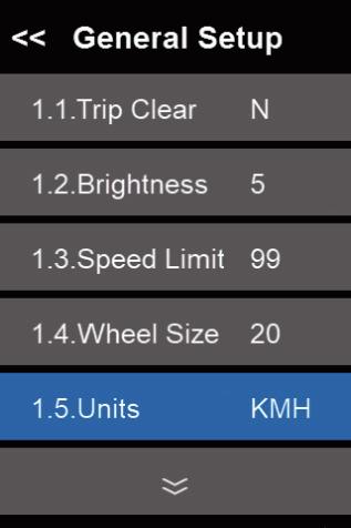
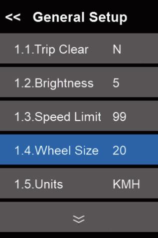


Click SET 2 seco n d s en ter th e g en eral settin g in terface. are as b elo w:
21
Gen eral Setu p Tr ip Cl ear
Backl ig h t settin g Sp eed Lim it settin g
W h eel d iam eter settin g U n i ts
Battery settin g Rid in g m o d e settin g
Y rep resen ts th e tu rn in g kn o b in to th e 6KM p u sh in g m o d e, an d


N rep resen ts th e star tin g tu rn in g kn o b to th e m axim u m .

A d v an ced setu p
Current limiting setting Poles In Motor setting Start After Poles setting
Throttle 6 KM
Exi t ECO N o r m al Po wer 22
Y means throttle with different level,
N means throttle with one level.

I t can be set to 3, 5, 6, 9. I f user select 3, the range of assist levels is 1 -3 .


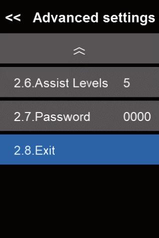

When the riding speed is 0 km/h for 5 minutes, the system will go to sleep automatically.

Th r o t t l e Lev el
Passw o r d A ssist l ev el s
I n fo rm ation Exi t Sav e & Exit .
23
Wire order deinition
24 W ir es seq u en ce W ir e s co l o r Fu n ct io n 1 Red Bat tery + 2 Bl u e W e ak l o ck 3 Bl a ck Bat t er y4 Gr een U A RT - RECEI V E ( RXD ) 5 Ye l l o w U A RT - SEN D ( TXD )
Common problems and solutions
Q: W hy the display is not able to start up?
A: Checking the connector that between display and controller.
O: How to deal with the error code?
A: F ix it to the maintenance place immediately. I f cannot be resolved, you can go to the electric vehicle repair points repair it in a timely manner.
Quality&Warranty
Any quality problems in normal case and in guarantee period, our company will responsible for the warranty
The warranty time is 1 8 months from date of purchasing.
Other items:
The following items are not belong to warranty scope
1 . I t can't be demolished.
2 . The damage caused by wrong installation or operation.
3 . S hell is broken when display is out of the factory.
4. W ire is broken.
5 . F orce disaster ( such as fi re, earthquake, etc. ) or natural di sasters like lightning, etc caused by fault or damage.
6 . Beyond W arranty period.
25
code table
Error code
0
Normal
Throttle error( S tart detection)
Motor no phase position
Hall error
Brake error( S tart detection)
7
Under voltage
Motor stalling
Communication controller receiv ing error
26
Defi nition
1 2 3 4 5 6
Communication display receiving error 8
9
The error code is corresponding with the fault definition.: Error
Battery Charging
Charging Procedure for On-bike Charging
Step1: Check the battery power indicator on your display.
Step2: Insert the plug inside the transformer
Step 3:
Step 4:
Insert the DC plug of the charger into the battery charging socket. Connect the power plug(110/220-volt plug) to the power socket.
NOTICE: This order helps extend the battery life and effectively reduces battery damage caused by improper charging.
Charging Procedure for On-bike Charging
Step 1:Find the keys located on the handlebar and remove them.
NOTICE:
Please keep your key and its spare in a safe place.
Step 2: Use the key to unlock the battery. While holding the battery with one hand, detach the battery by turning the release switch located on the underside of the frame.
27 27 27
◆
◆
Step 3:
Check the battery status
N O TI CE: Please write down the serial number found on the pattery beneath the parcode on the inside front cover of this manualto facilitate failure reporting.
P roducts that have the serial number and/or barcode remov ed, defaced, damaged, altered, or made illegible will not be covered by the warranty.
Step 4 : S a
First, assemble the charger by inserting the pluginto the transformer. Then insert the DC pluginto the battery charging socket.
Last, insert the power plug 0/220 vot plug) to the power socket This order helps extend the baitery ife and eftectively reduces oattery damage caused by
fest way to charge your battery improper charging.
The charger works on 1 1 0 /2 2 0 V 5 6 /6 0 Hz standard home AC power outlets. Do not open the charger to select voltage input as the charger can automatically detect and account for incoming voltage.
28
Light Status Charging Status Red ( on charger ) Charg in g Green ( on charger ) Fully charged Yellow ( on battery ) 4 0 % - 6 0 % power Red ( on battery ) < 4 0 % power
P roject Unit Minimu m Max Battery I nput V oltage V 28 55 S tandby current mA 0. 1
1.Please unplug the main power supply first by removing the plug from the power socket then remove the Dc port from the battery. You can then check the battery status on the display screen.
2.Hold the battery with one hand and tun the release switch with the other hand to install the bottery. Lock the battery when finished to prevent theft. battery displays abnormal charging behavior, such as:
• Longer-than-expected charge time
• S trange smell, smoke, or liquid emanating from battery and/or charger
• Overheating battery and/or charger
P lease stop charging and contact Yotobike immediately.
• The battery can be recharged on or off the bike.
• A new battery may take longer to be fully charged when depleted.
• The charger will automatically stop charging once the battery pack is fully charged.
• You can recharge the battery after short rides as it does not have a memory effect.
•
• W hile charging, please keep your battery away from direct sunlight, liquid, dirt or debris, and metal objects. Do not allow the battery to be charged in
• D o not cover the charger when environments under 14° Fahrenheit (-10° Celsius) and over 104° Fahrenheit (40° Celsius ). charging.
• Keep the battery away from children while charging.
• Make sure to only use an approved Yotobike charger purchased directly from Yotobike for your specifi c bike serial number.
NOTI CE : I f your
◆ ◆ ◆ 29
Before Riding
Ensure that the battery has been properly secured to the bike before each use by grasping the battery pack and pulling upwards, testing the security of the pack.
Battery Maintenance
(48V 20Ah Battery with Samsung Cells)
Do not fully drain your battery. Turn off the power when the battery charge is low.
Fully charge the battery after each use, no matter how much power is used. This will prolong the battery life. If battery power is not used for a long time, store the battery with a full charge and charge it once a month.
The Yotobike can be safely ridden in lightrain. However, riding through very heavy downpours or through flooded streets is not recommended, as the
crank and/or motor can get wet, which may cause damage.
Keep the battery away from open flame and other high-temperature heat sources. Do not expose the battery to direct sunlight or recharge immediately
after use in high-temperature weather.
NOTICE:
It is not recommended to make any modhcations to the battery or the motor. if the battery is tampered with, and there are any probiemswitn
the altered battery or motor, it will not be covered under Yotobike warranty.
Charger care information
Please refer to the instruction manual in the charger box.
◆
• • • • ◆
◆
30
Riding Modes
Pedal-assist
to arrive fresh and timely at work, without being sweaty and exhausted.
Lower pedal setings (u/2) are popular for Yotobike riders to use ofter work or when leisurely exercise is prefered. These are best to use on the way work,
to refresh yourself and relieve stress accumulated throughout the entire workday. Moreover, lower settings can extend usable range for longer rides, maximizing enjoyment while minimizing physical stress and fatigue.
the motor to assist, but not replace, your own pedaling effort . When you are ◆ ◆
Throttle-only
The throttle mode is similar to how a motorcycle or scooter operates, alleviating the need to pedal or providing an additionalboost simply by twisting the throttle.
Leopard can reach speeds of up to 25 miles per hour with throttle mode, which not only allows you to travel faster, but also reassures riders with extra omising comfort or safety, the throttle-assisted Yotobike would be your perfect companion. power whenever needed, depending on traffic conditions and rider energy levels. lf you are an adventurer who chases after speed and distance without compr
31
Pedal-Assist is an operating mode on e-bikes designed to engage your bike in the pedal assist mode, you can adjust the setting according to your preference.Yotobike has five pedal assist settings - ranging from 1 to 5. want Hioher peddl settinas L4/5) would be most helofu for those who want to ride faster with minimum effort. These setinas are perfect for people who • •
I n this mode, the Yotobikewill perform like a normal bike, as you’ll be riding without any assistance from the motor. This mode is especially useful if you run out of battery, or are looking for more intensive resistance training.
We suggest that you select a lower assistance level when you first ride your Yotobike. After becoming more comfortable witthe riding characteristics of our e-bike,
and more familiar with the varvino range recuirements of vour most common destinations and commuting routes, you can then make any needed adjustments to pedal assist settings, as well as throttle use frequency, riding position, etc.
Riding Limitations
F ollowing are some limitations needing riders’ careful attention to ensure the mid motor does not overheat or become damaged from excessive loading:
• Do not attempt to ride up hills steeper than 15 % grade.
• Use the pedals to assist the motor when climbing hills and accelerating from a stop.
• Avoid sudden starts and stops.
• G enerally accelerate at a moderate pace, rather than aggressively.
◆ 32
Pedal-only
Parking & Transport
Follow these basic parking, storage, and transport tips to ensure your bike is well cared for , both on and off the road:
• W hen walking with the bike, turn off the power to avoid accidental acceleration.
•
•
Though our bikes are water resistant (PX4 Water Resistance), please do not park your bike outdoors in cold or inclement weather for extended periods. hen parking, switch the power and any lights off to conserve battery, remove the key from the bike, and ensure the battery is secured and locked to the frame.
• In public places, help keep your Yotobike safe and secure from theft by always locking it up.
• Make sure to not park, store or transport your Yotobike on a rack that is not designed for the size and weight of the bike. W hen storing or carrying your bike on a rack for transport, remove the battery to reduce the weight and make li fting or loading easier.
Carrying Loads&Leopard
Total Payload Capacity of Leopard W eight: 7 0 lbs
Cargo Safe Operation Tips:
The following list provides important tips for the safe operation of the Leopard when used for carrying cargo:
1 . Make sure to load the cargo as low as possible to lower the center of gravity and improve stability.
2 . Ensure your loads are properly secured and periodically check that nothing has loosened.
3 . Plan your route accordingly when cargo is loaded on the Leopard, considering hill climbing ability , steering, and braking . Also account for
moderately reduced range when carrying extra cargo weight (or an additional passenger).
4 Try to get a feel for the cargo load in a flat and open private area before riding on public roads.
5. loss
Make sure to not use the front brake by itself, with or without cargo. Always apply the rear brake first followed by the front of control is possible when the front brake is operated independently, especially at higher speeds.
6 The kickstand is not designed to hold the bike upright with cargo by itself, always manually hold the bike upright when loading or carrying cargo
33
◆
Safety and Care Instructions
To clean the e- bike, wipe the frame with a damp cloth soaked in a mild, non- abrasive, non- corrosive detergent mixture. Wipe or spray all unpainted parts with anti- rust treatment after being used in coastal areas or areas with salty air or water
Never immerse the bike or any components in water, as the electrical system may be damaged . If the hub and bottom brack et bear ingshave been
submerged in water, they should be removed and re-greased (this will prevent accelerated bearing deterioration). eriodically check wiring and connectors to ensure there is no damage, and the connections are secure. Store under shelter, avoiding extended exposure to cold or inclement weather If exposed to rain or excess moisture, dry your b icycle afterward and apply anti- rust treatment to the chain and any other unpainted steel surfaces.
Regularly clean and lubricate all moving parts, tighten components and adjust as required
Your cables, spokes, and chain will stretch af ter an initial break in period of 8 0 - 1 6 0 km, and additionally bolted connections can loosen with time and
usnoe. Thereore. we sucoest vou contoct a certifed bicvcle mechanic every two months to ensure vour bike is safe and probiem-free for vears of use measure)
If the paint has become scratched, or the metal chipped, use touch- up paint to prevent rust ( clear nail polish can also be usedas a preventative
amage from corrosion is not covered under warranty, therefore special care should be given to protect and extend the life of y our bike.
P
D
34
Battery Maintenance ( 48V 20Ah Battery with Samsung Cells )
Don't fully drain your battery. Turn off the power when the battery charge is low.
Fully charge the battery after each use, no matter how much power is used. This will prolong the battery life. If the battery i s not used for a long time, store the battery with a full charge and charge it once a month.
The Leopard can be safely ridden in light rain. However,riding through very heavy downpours or through flooded streets is not recommended, as the
crank and/or motor can get wet, which may cause problems.
Keep the battery away from open flame or a high-temperature heat source. Do not expose the battery to direct sunlight or recharge immediately after
use in high-temperature weather.
We recommend cleaning the chain after each ride, especially in rainy and humid environments. Use a dry cloth to wipe the chain and its accessories clean. Use a brush to remove sand and dirt stuck in the chain, along with use warm soapy water if needed. Do not use strong aci dic or alkaline cleaning
Apply lubricating oil after cleaning to avoid rust. First, make sure the chain is dry, and then apply the lubricating oil into
the bearings.
To prevent unnecessary chain wear, try to maintain a vertical chain position when shifting gears (do not use the smallest gear with the smalest flywheel, or the largest gear with the largest flywheel, etc.)
Always use a clean, oi-free lint-free cloth with plain or soapy water to clean your bike.To prevent water from ftowing into the front fork, you can turn the bike upside down. Dry with a lint-free towel fter washino. ay soecific atention to the inner tube and the dust seal to reduce wear and prevent thining of the inner tube, which can lead to significant damage if the aluminum is exposed to air.
2. We recommend using a front fork dust cover to protect the inner tube of your front fork. This prevents dust from entering as well as hard objects from hitting the inner tube.
1. 1. 2. 3. 4.◆
1. 2. 3.
35 Chain Maintenance Front Fork Maintenance ◆
◆
Warranty
Yotobike periodically updates our official Warranty Policy.Therefore, please review the latest policy on our website:
https://yotobike.com/
After-sales Mail: support@yotobike.com
36