2 minute read
10 Guide plates


10.1 Calibrating upper guide plates
17 mm 19 mm 4 mm 6 mm
Saddle is driven under the front part of the upper guide plates (Figure 10.3). Upper guide plate height calibrated with the 19 mm wrench on bolt (45) (Figure 10.1) until it is 4 mm above the teeth of the saddle (Figure 10.3). Saddle is driven under the rear upper guide plate (Figure 10.4) and a gap calibrated on bolt (46) with the 17 mm wrench at 6 mm above the saddle cog (Figure 10.4).
45
Figure 10.1 46

Figure 10.2
Adjust space to 4 mm

Figure 10.3
Adjust space to 6 mm

Calibrating upper guide plates
13 mm 1.5 mm 3 mm 5 mm 6 mm
Adjust the gap between the knife and the upper guide plate to 1 mm (plate turned to or from the knife). Make sure that the gap does not exceed 2 mm, otherwise the fish tails will be flawed (Figure 10.5). Gap between the upper guide plate should be set 5–6 mm in front of the plastic sheaths of the separating knives and 10–14 mm behind the separating knives (Figure 10.6).
Knife and plate must always be parallel!
Back 1 mm

Figure 10.5
5–6 mm
Front
10–15 mm
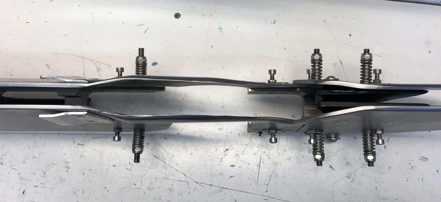
Figure 10.6
NOTE! It is important that the sheath always covers the separating knives.

Figure 10.7 Do not remove the bolts – just loosen the spring nuts (Figure 10.10) to remove plates! 5–6 mm

Figure 10.8 Pre-stress is set at 2–4 kg.
Gap between plate and back knives should be 1 mm.

Figure 10.9 Here you can set the gap between the separating knife sheaths and also increase the distance between the plate and the back knives. Spring nuts

Figure 10.10
10.3 Insertion
To adjust the various guiders which hold the fish as it goes through the machine, select ‘Settings’ on the screen and then ‘In-feed’.
The values in the ‘In-feed’ menu show how much pressure (bar) is in on the guide plates. To adjust these values, press the relevant value to call up a keyboard, enter the new value and press ‘Enter’.
17 mm
47

0.0 3.5 2.0
0.0 2.0 1.0
Figure 10.11
0.0 2.0 1.0
0.0 5.5 4.0
1 2
User
Figure 10.12

In-feed gap adjusted with nuts (47).
10.4 In-feed – Manual settings
If the in-feed plates are uneven or unevenly tight, their position can be adjusted by loosening the bolts (48) on the cogs, adjusting the plates to the correct position and retightening.
48
Figure 10.13


