SANTINO D’ANGELO
ARCHITECTURE PORTFOLIO SELECTED WORKS 2023


santino.dangelo@hotmail.com647-518-0808
As an architecture student graduating from an acredited program, I am looking to secure a starting position to develop tangible and intangible skills whilst assisting members in any manner needed to complete the task at hand
OSSD
St. Ignatius of Loyola Catholic School, Oakville, ON (September 2015- June 2019)
Bachelors of Architectural Science
Toronto Metropolitan University, (formerly Ryerson) Toronto, ON (September 2019- 2023- Graduation in October)
Oakville Soccer Club
- Under 8 boys assistant soccer coach
- Provided basic fundamental skills in the sport of soccer
(October 2018- August 2019, September- December 2022)
Skills
Skills
-Provided essential values such as respect, team-work, dedication, passion among others to complement the education received domestically
- Developed communication, organization, team-work and leadership skills to ensure a correct conduction of activities dealing with young children
College Pro- Window Cleaner
- Responsible for cleaning windows and gutters in residential areas
(May 2020- August 2020)- Seasonal Job
- Required teamwork, communication and organization to unsure safety of all workers and ultimately deliver a great service for the client
- Constant communication with client, enhancing communication skills and ability to solve problems
Ikea- Order Picker
- Responsible for collecting and delivering costumer orders on time
- Given the responsibility of storing products and completing regular inventory check
- Developed an understanding of logistics within the industry as well product specifications
(August 2021- January 2022)
- Developed the ability to adapt quickly to a fast moving environment, providing the best service to ensure costumer satisfaction
CLV Group- Landscape Crew Worker
(May 2021- September 2021)- Seasonal Job
- Assisted on cutting, trimming and edging property gardens and grass areas owned by the company
- Assisted in completing such tasks and others in order to maintain the properties in good conditions for residents
- Developed an understanding or irrigation systems and landscape design
-Combined knowledge previously obtained in post-secondary education to guide the maintenance of the properties and ensure a consistent composition of landscaping spaces
Software Skills
Interest
- Rhino
-SketchUp
- AutoCAD
- Revit
- Enscape
- Adobe Suits (Ilustrator, Photoshop, InDesign)
Fabrication Skills
- Physical model making
-Laser Cutting
- Woodworking
- 3D Printing
Languages
- Spanish
- Native language
- Portuguese
- fluent proficiency in speaking and writing
- English
- fluent proficiency in speaking and writing
- Italian
- basic knowledge
Introudcing a community in a historically forgetten town in the South of Italy
Page 1
Finding alternative ways to densify an area of the city with strict zoning bylaws
Page 9
Reporpusing Hamilton’s dowtown to create a community landmark while stimulating a healthy lifestyle
Page 15
Introducing a multiuse temporary pavillion on Gore Park aimed to provide a quiet space for the community
Page 25
Year: 2022- Semester 6
Size: 1400 m2
Location: Hamilton, ON
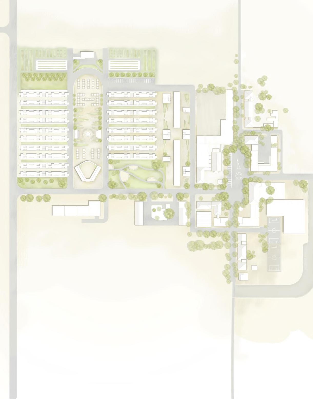
The newly proposed community center for Borgo Segezia looks to tie in the existing foundations of the past to create a permanent place that stands the test of time. A combination of simplicity and durability that bleeds into the language of the building, with a brutalist approach that prioritizes a strong and durable material like concrete. Simultaneously the building looks to provide a place that is currently lacking in the town and that naturally becomes necessary as a master plan surrounding new housing is proposed.
The community center is located adjacent to the existing school, taking the vertical rhythm as inspiration and opening the possibility for connection and expansion of the program, integrating community needs into one portion of the town, on the exterior of the main town piazza. Additionally the project starts from the revitalization of the existing multi use court located on the southeast corner of the town, from which the expansion then takes place.
A joint of e ort of the group, (integrated by Amal Shawer, Oscar Ayala, Daniella Haddadin and Santino D’Angelo Rozas) saw the development of a master plan that seeked to create a community that integrates housing, social spaces, commercial and communal activities, increasing the density of Borgo Segezia and providing a new home to those in need in the region of Puglia. Consequently, the group understood the need to complete this master plan in four di erent stages as population grows and the needs increase. During the first phase of the project the master plan looks to create a new piazza where the aforementioned components can merge and coexist, merging residential space with temporary markets and open public spaces. Simultaneously and in direct correlation with the ultimate goal of expansion, Phase 1 of the master plan proposes also the development of a community/ sports center, located on the Southeast portion of the town.
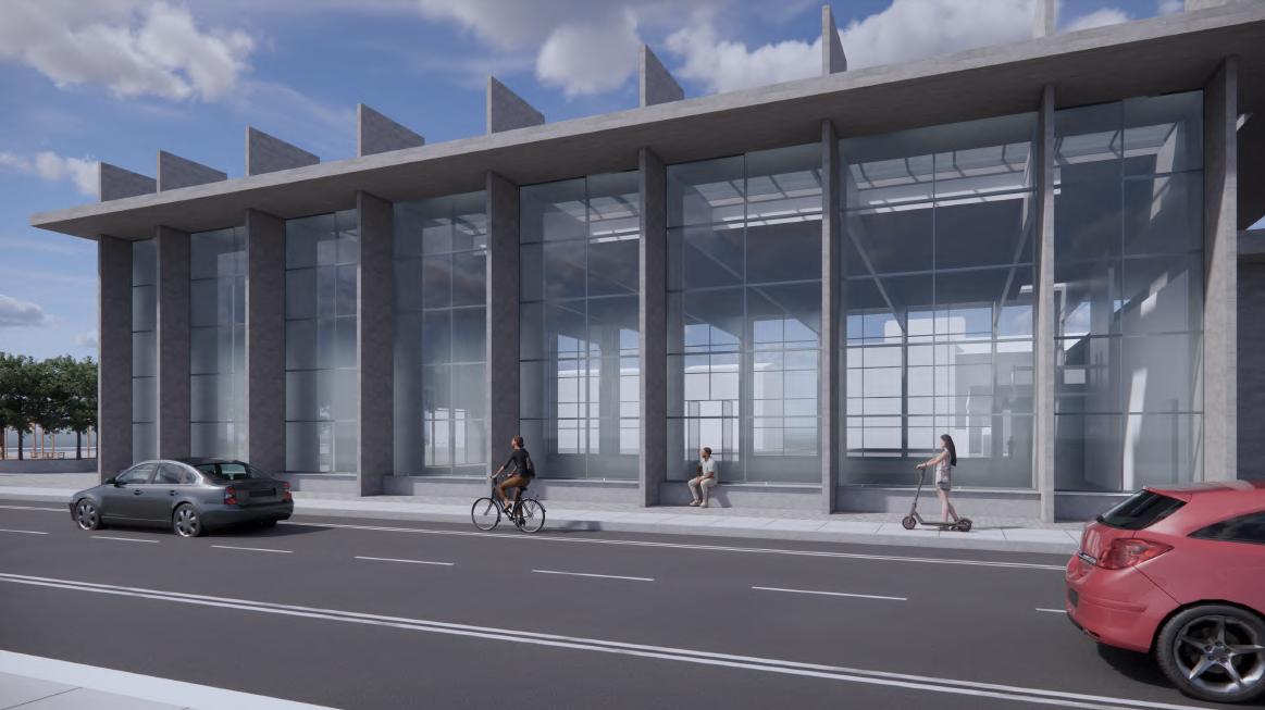
The simplicity of the design comes not only from the overall geometry also but the choice of detailing throughout the building, giving an aesthetic and technical use to the components that make up the building. Detail 1 showcases the skylight and its connection with the roof plane, which merges into the drain system. The drain system is hidden within the interior of the concrete blades that make up the vertical rhythm that originates at the main elevation of the building.
Thesimplicityofthedesigncomesnotonlyfrom theoverallgeometryalsobutthechoiceofdetailing throughoutthebuilding,givinganaestheticand technicalusetothecomponentsthatmakeupthe building.Detail1showcasestheskylightandits connectionwiththeroofplane,whichmergesinto thedrainsystem.Thedrainsystemishiddenwithin the interior of the concrete blades that verticalrhythmthatoriginatesatthemainelevation of
OntheotherhandDetail2showcasestheinteri-or/exteriorbench,foundbetweentheconcrete bladesandprovidingasittingplaceforusersonthe interiortositaswellasthoseontheexterior.The detailproducesanotherusablespaceinthe build-ingwhileperformingthetechnicallabourof an-choringthecurtainwall,foundationandhousing
the return duct for the air
Thesimplicityofthedesigncomesnotonlyfrom theoverallgeometryalsobutthechoiceofdetailing throughoutthebuilding,givinganaestheticand technicalusetothecomponentsthatmakeupthe building.Detail1showcasestheskylightandits connectionwiththeroofplane,whichmergesinto thedrainsystem.Thedrainsystemishiddenwithin that make up the verticalrhythmthatoriginatesatthemainelevation of the building.
On the other hand Detail 2 showcases the in-teri-or/exterior bench, found between the concrete blades and providing a sitting place for users on the interior to sit as well as those on the exterior. The detail produces another usable space in the build-ing while performing the technical labour of an-choring the curtain wall, foundation and housing the return duct for the air conditioning.
OntheotherhandDetail2showcasestheinteri-or/exteriorbench,foundbetweentheconcrete bladesandprovidingasittingplaceforusersonthe interiortositaswellasthoseontheexterior.The detailproducesanotherusablespaceinthe build-ingwhileperformingthetechnicallabourof an-choringthecurtainwall,foundationandhousing conditioning.
Year: 2023- Semester 7
Size: 80 m2
Location: 542 Beresford Avenue, Toronto, ON
Located within a residential zone, the laneway suite emerges as a way to gently densify a city that lacks the concept of the missing middle due to zoning regulations. The given site opens the possibility to expand beyond the legal limitations of laneway suites in the city, in which a live-work condition was developed, orienting the design for a home owner that requires a wooden oven, an element which bleeds into the materiality, spacial organization and form development.
Volumetrically the suite is conformed by accentuated horizontal roof planes that correspond with the spaces in the house that extrude from the outside walls and at the same time are intersected and pierced by solid vertical elements that not only cut the planes in elevation but also provide a seperation of spaces in plan
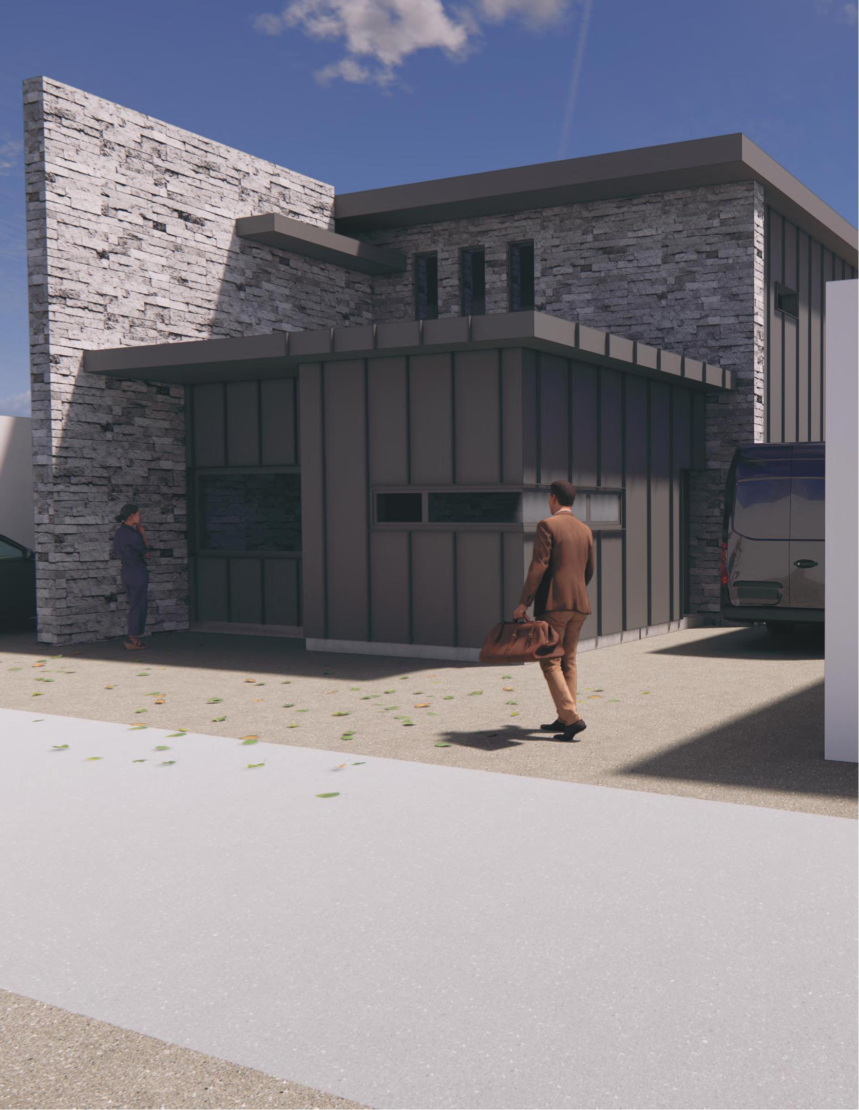 Exterior View from Laneway
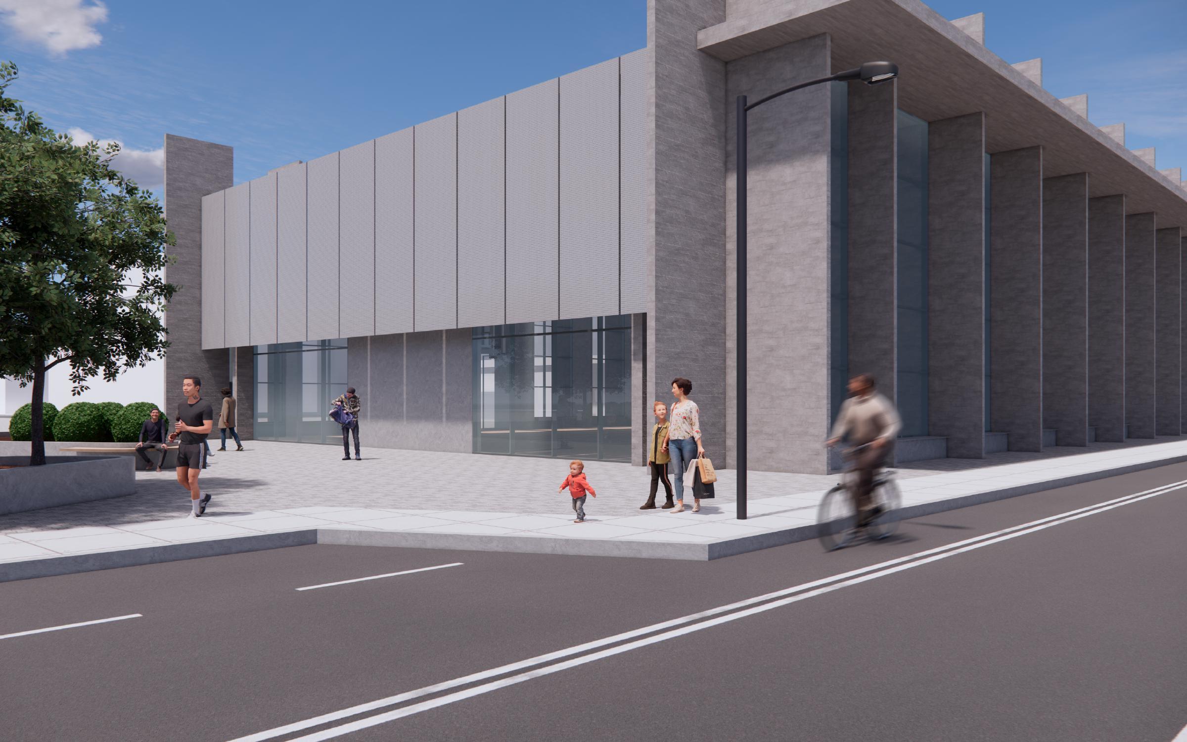
Year: 2022- Semester 6
Size: 6700 m2
Location: Hamilton, ON
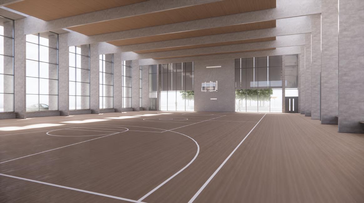
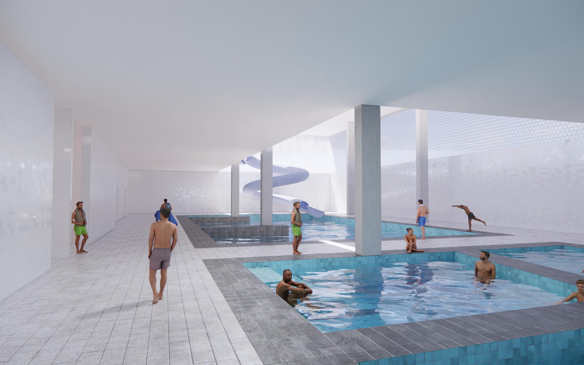
Located within the downtown core of the city of Hamilton and adjacent to Gore Park, a symbol and landmark in the city’s history, the Hamilton Aquatic Centre rises as a landmark for a newly defined urban block achieved through the action of a group urban master plan redesign. The aquatic center rises as a threshold and provides entrance to a continuous circulation through the site, connecting Gore Park with the a oredmentioned master plan, replac-ing the the existing podium infrastructure.
This pedestrian circulation is then the driving force behind the design intention, eroding through the building to create two distinct masses that are connected by programmatic elements above and below grade. The separation of masses creates two distinct moments in the building which consequently a ects the facade choice and subsequent detailing processes.
MECHANICAL DUCTS (RETURN)
2. SUPPORTING METAL BRACE
3. SUSPENDED CEILING
4. CURTAIN WALL
5. CONCRETE ENCLOSED COLUMN
6. MECHANICAL DUCT (SERVICE)
7. ALUMINUM CATWALK
8. GLAZED SPANDREL PANEL
9. END- FIXED WOODEN LOUVER
10. OPEN-WEB STEEL JOIST
11. RAISED FLOOR
12. ALUMINUM MULLION CAP
D-PEDESTRIAN WALKWAY ASSEMBLY PAVING STONE
MEMBRANE
RIGID INSULATION BOARD
BARRIER
CONCRETE SLAB
A- TYPICAL ROOF ASSEMBLY
WATERPROOF MEMBRANE
EXTERIOR SHEATING
150MM RIGID INSULATION BOARD
VAPOUR BARRIER
20MM POURED CONCRETE
40MM STEEL DECK
OPEN WEB STEEL JOIST
W27 X 161 STEEL BEAM
C- TYPICAL SPANDREL PANEL ASSEMBLY
GLAZED SPANDREL PANEL
AIR BARRIER
50MM EXTRUDED POLYSTYRENE INSULATION
VAPOUR BARRIER EXTERIOR SHEATING
B- TYPICAL PARAPET ASSEMBLY
COMPOSITE METAL PANEL
AIR BARRIER
50MM EXTRUDED POLYSTYRENE ISULATION EXTERIOR SHEATING
CONCRETE POUR
EXTERIOR SHEATING
50 MM POLYSTYRENE CONTINUOUS INSULATION
AIR BARRIER
D- TYPICAL FLOOR ASSEMBLY
FINISHED HARDWOOD FLOOR
RAISED FLOOR SUPPORTING STRUCTURE
200 MM POURED CONCRETE
40MM STEEL DECK
W27 X 161 STEAL BEAM
OPEN WEB STEEL JOIST


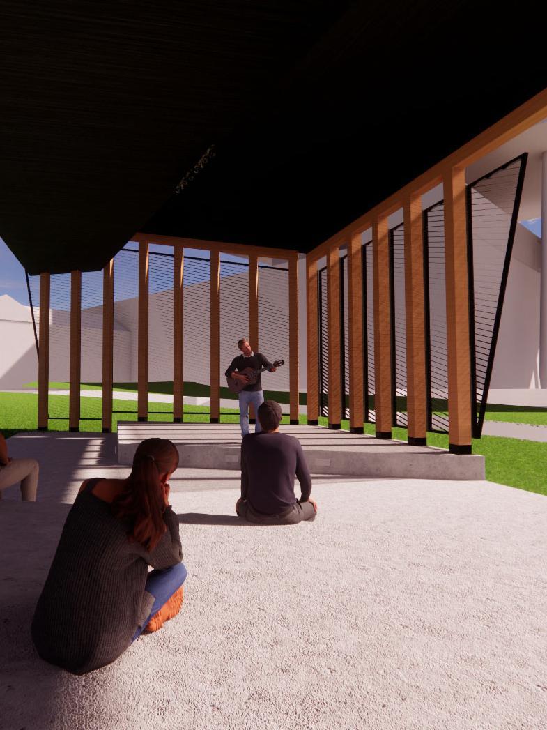
Year: 2020- Semester 3
Size: 116 m2
Location: Toronto, ON
Serving as a flexible space, the pavillion, intended mostly for live performances looks to provide a calm place for visitors of Grange park to enjoy. The design intention sorrounds the idea of balance between openess and enclosure. The pavillion maintains a mostly open profile, with large openings on its East and West sides, but provides a semi enclosure with heavy timber columns and perforated metal screens that serve as space delineating walls.
The warmness of the heavy timber columns and beams provides a comfortable environment to the users, while contrasting with the rigidity of the concrete and lightness of the steel panels. The open layout of its ‘interior’ allows for a flexible usage, weather it is hosting a performance or simply serving as a space for users to gather and enjoy their time in a place surrounded by the impressive architectural features of the AGO and OCAD University