Instruction Manual
DVC6200 Digital Valve Controller
D103409X012
June 2011
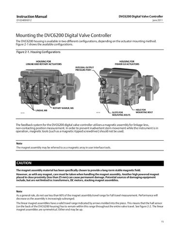
Mounting the DVC6200 Digital Valve Controller The DVC6200 housing is available in two different configurations, depending on the actuator mounting method. Figure 2‐1 shows the available configurations. Figure 2‐1. Housing Configurations HOUSING FOR LINEAR AND ROTARY ACTUATORS
HOUSING FOR FISHER GX ACTUATORS INTEGRAL OUTPUT PRESSURE PORT
ROTARY NAMUR, M6 LINEAR, M8 W9703
W9704
SLOTS FOR MOUNTING BOLTS
HOLE FOR MOUNTING BOLT
The feedback system for the DVC6200 digital valve controller utilizes a magnetic assembly for linkage‐less, non‐contacting position measurement. In order to prevent inadvertent stem movement while the instrument is in operation, magnetic tools (such as a magnetic‐tipped screwdriver) should not be used.
Note The magnet assembly may be referred to as a magnetic array in user interface tools.
CAUTION The magnet assembly material has been specifically chosen to provide a long‐term stable magnetic field. However, as with any magnet, care must be taken when handling the magnet assembly. Another high powered magnet placed in close proximity (less than 25 mm) can cause permanent damage. Potential sources of damaging equipment include, but are not limited to: transformers, DC motors, stacking magnet assemblies.
Note As a general rule, do not use less than 60% of the magnet assembly travel range for full travel measurement. Performance will decrease as the assembly is increasingly subranged. The linear magnet assemblies have a valid travel range indicated by arrows molded into the piece. This means that the hall sensor (on the back of the DVC6200 housing) has to remain within this range throughout the entire valve travel. See figure 2‐2. The linear magnet assemblies are symmetrical. Either end may be up.
15