Pforte Wicket Anweisung Installation manual
2 Inhaltsverzeichnis 1. Wie benutzt man die Anleitung? ...................... 1 1.1. Sicherheitshinweise ............................. 1 1.2. Andere Konventionen ........................... 1 2. Zweckgemäße Verwendung .......................... 2 3. Allgemeine Informationen 3 3.1. Allgemeine Sicherheitshinweise ................... 3 3.2. Schematische Darstellung der Pforte und wichtige Definitionen 4 4. Inhalt der Lieferung ................................. 5 4.1. Konstruktionselemente der Pforte 5 4.2. Zubehör ....................................... 5 5. Vorbereitung der Streifenfundament ................... 6 6. Montage der Pforte ................................. 9 6.1. Montage von Scharnieren ........................ 10 6.2. Montage des Torflügels .......................... 12 6.3. Montage der Anschlagleiste ...................... 13 6.4. Montage der Abdeckleiste ........................ 14 6.5. Pforte - Einstellung ............................. 15 7. Lagerung und Transport .............................. 16 7.1. Lagerung ...................................... 16 7.2. Transport von Pforten ........................... 16 8. Wartung ........................................... 17 9. Entsorgung ........................................ 17 English version . . . . . . . . . . . . . . . . . . . . . . . . . . 19 II
1 . Wie benutzt man die Anleitung?
1 .1 . Sicherheitshinweise
Warnung – Warnt vor leichten Verletzungen und Sachschäden.
Struktur, Sicherheitstipps:
Auswirkung der Bedrohung
Quelle der Bedrohung
Warnung!
Abhilfemaßnahmen
Hervorhebung wichtiger Inhalte:
Wichtig! Wichtiger Tipp
1 .2 . Andere Konventionen
1.2.1. Anweisungen
Anweisungsstruktur:
Führen Sie diesen Befehl aus. Beschreibung der Ergebnisse, wenn betrifft
1.2.2. Liste
Listenstruktur
Erste Listenniveau
Zweite Listenniveau
1.2.3. Legende
Abmessungen
Elemente
Pfortenikone
Ort, auf den sich die Zeichnung bezieht
Montageanleitung Pforte 1
2 . Zweckgemäße Verwendung
Die Pforten der Firma KONSPORT sind für die Umzäunung von Außengeländen und Eingängen in Privatbesitz und Gewerbeobjekten bestimmt.
Das Design der Pforten ermöglicht die Installation einer Gegensprechanlage mit einem Elektrochloss
Unnötige Lasten dürfen nicht an der Pforten aufgehängt werden. Dies ist nicht bestimmungsgemäß und Schäden, die dadurch entstehen, sind nicht von der Garantie abgedeckt.
Das Produkt sollte von einem spezialisierten Montagebetrieb montiert werden.
Wichtig!
Selbstmontage führt dazu, dass keine Garantie für die Montage und den ordnungsgemäßen Betrieb der Pforte besteht.
2
3 . Allgemeine Informationen
Die Pforten der Firma KONSPORT sind Produkte, die auf der Grundlage von Tabellen mit standardisierten Abmessungen hergestellt werden. Diese Montageanleitung beschreibt nur die Montageregeln für ein Tor, das auf Standardabmessungen basiert.
Wesentliche Produktparameter werden immer auf Bestellung spezifiziert. Voraussetzung für die Gewährleistung der Montage und des ordnungsgemäßen Funktionierens ist, dass die Montage durch einen Fachbetrieb durchgeführt und im Abnahmeprotokoll bestätigt wird (siehe Bedienungsanleitung). Ohne unterschriebenes Abnahmeprotokoll deckt die Garantie nur Herstellungsfehler des Produkts ab.
Die Verzinkung ist ein Prozess, der die Witterungsbeständigkeit des Produkts erhöht. Zink ist keine dekorative Beschichtung. Feuerverzinkung ist kein Prozess, der die Ästhetik des Produkts erhöht. Die Verdickung, leichte Rauheit der lackierten Oberflächen, die auf den Waren des Verkäufers auftreten können, ist das Ergebnis des Feuerverzinkungsprozesses und unterliegt keiner Beanstandung.
Es wird empfohlen, die Pforte einmal jährlich von einem Fachunternehmen überprüfen zu lassen, das bei Bedarf die notwendigen Regelungen trifft. Dies garantiert eine jahrelange einwandfreie Nutzung.
3 .1 . Allgemeine Sicherheitshinweise
Beschädigung der Pforte durch unsachgemäßen Gebrauch.
Das Aufhängen am Gewichtstor, das Betreten der Pforte droht, die tragenden Elemente der Pforte zu beschädigen.
Warnung!
Beladen Sie die Pforte nicht mit zusätzlichen Gewichten!
Montageanleitung Pforte 3
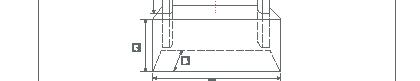
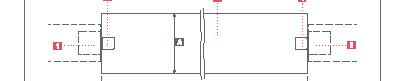
A Pfortenlicht
B Pfortenflügel

C Bodenfreiraum
1 Anschlagpfosten


2 Streifenfundament

3 Anschlagleiste
4 Tragpfosten

Bodenfreiraum C – Abstand des Torflügels von der geplanten Bodenhöhe, der für die freie Bewegung des Tores notwendig ist = 6 cm.

Pfortenlicht A –die zwischen den Türpfosten gemessene Breite

4
4 . Inhalt der Lieferung
Montageanleitung Pforte 5
4 .1 . Konstruktionselemente der Pforte 1. Pfortenflügel 1 St. 2. Anschlagleiste 1 St. 3. Tragpfosten 2 St. 4 .2 . Zubehör 1. Scharniere 4 Sets. 2. Handgriffe 2 Sets. 3. Schloss (mit Einsatz und Schild) 1 Set 4. Montageschrauben 1 Set 5. Farbenstift (optional) 1 St. 6. Abdeckleiste (optional) 1 St.
5 . Vorbereitung des Streifenfundamentes
Rissiges Streifenfundament.
Beton, der bei ungünstigen Witterungsbedingungen gegossen wird, kann reißen.
Warnung!
Beim Gießen von Beton darf die Umgebungstemperatur nicht unter –5°C liegen.
Wichtig!
Um die Streifenfundament richtig zu gießen, ist eine detaillierte Beratung mit dem Investor notwendig, insbesondere hinsichtlich ihrer Höhe und des endgültigen Aussehens der Fläche unter der Pforte.
Wichtig!
Die Tiefe des Grabens an die örtlichen Bedingungen des Einfrierens des Bodens anzupassen.
6
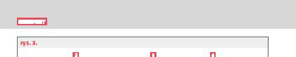
A Streifenfundamentlänge
B 30-40 cm
C min. 1 m
D Höhe des Torflügels+ Bodenfreiraum
E Pfortenlicht

1
Bestimmen Sie den Ort der Ausführung der Streifenfundamentes 1

Streifenfundamentlänge A = Pfortenlicht E + Breite der beiden Pfosten + ungefär 20 cm

Streifenfundamentbreite B = 30-40 cm
Machen Sie einen Graben unter den Streifenfundament
in der Linie des vorhandenen Zauns
Streifenfundamenttiefe C beträgt mindestens. 1 m
das Streifenfundament gießen
behalten Sie die Abmessungen A und B und C

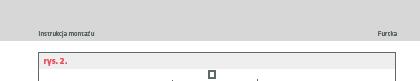
Beton mindestens der Klasse B20 verwenden
Höhe des Streifenfundamentes bis zum Boden nach Absprache mit dem Investor (z. B. wegen des Plans der Verlegung des Pflastersteins)
7
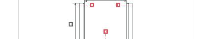
Streifenfundament
2 Anschlagpfosten
3 Tragpfosten
A 30-40 cm
B Länge des Streifenfundamentes
1 Endpfosten
2 Anschlagpfosten
3 Streifenfundament
4 Tragpfosten


5 Endpfosten des Zaunes
Den Anschlagpfosten in Streifenfundament 2 eintauschen im Einklang mit dem vorhandenen Zaun
die Höhe des Pfostens über dem Boden wird bestimmt
durch die geplante Höhe des Tores

Wiederholen Sie die Schritte mit dem Tragfosten 4
Das gegossene Streifenfundament mit eingebetteten Tragpfosten lassen Sie für 14 Tage, um den Beton zu binden
Nach dem Einbetten der Pfosten überprüfen Sie die Maße erneut E
Wichtig!
D (Abb. 2)
8
6 . Montage der Pforte
Nach 14 Tagen nach dem Gießen des Streifenfundamentes können Sie mit der Installation der Pforte fortfahren.
Wichtig!
Voraussetzung für die Gewährleistung der Montage und des ordnungsgemäßen Funktionierens ist, dass die Montage durch einen Fachbetrieb durchgeführt und im Abnahmeprotokoll bestätigt wird (siehe Bedienungsanleitung). Ohne unterschriebenes Abnahmeprotokoll deckt die Garantie nur Herstellungsfehler des Produkts ab.
Wichtig
Alle Zeichnungen zeigen die Montage der Pforte aus der Perspektive einer Person, die vor dem Grundstück steht (nach Bestellung). Zur Präsentation zeigen die Montagezeichnungen die Situation von der Seite des Grundstücks!
Montageanleitung Pforte 9
6.1. Mont a ż z aw iasów
6.1. Mont a ż z aw iasów
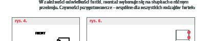
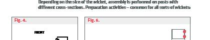
W zależności od wielkości furtki, montaż wykonuje się na słupkach o różnym przekroju. Czynności przygotowawcze – wspólne dla wszystkich rodzajów furtek:
W zależności od wielkości furtki, montaż wykonuje się na słupkach o różnym przekroju. Czynności przygotowawcze – wspólne dla wszystkich rodzajów furtek:
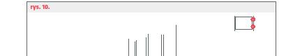
rys. 4.
rys. 4.
r ys. 6 .
r ys. 6 .
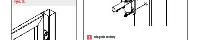
rys. 5.
rys. 5.
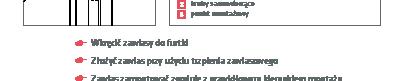
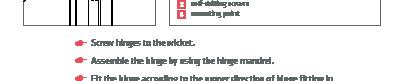
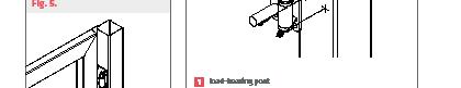
a s ł upe k noś ny
a s ł upe k noś ny
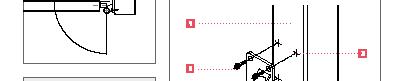
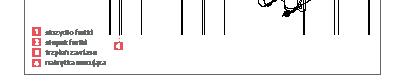
1 Tragpfosten

b ś r u b y s a mowiercące
b ś r u b y s a mowiercące
2 selbstbohrende Schrauben
c pu n k t mont a żowy
c pu n k t mont a żowy
3 Montagepunkt
Wkręcić zawiasy do furtki
Wkręcić zawiasy do furtki
Schrauben Sie die Scharniere an die Pforte
Złożyć zawias przy użyciu trzpienia zawiasowego
Złożyć zawias przy użyciu trzpienia zawiasowego
Falten Sie das Scharnier unter Verwendung des Scharnierbolzen
Zawias zamontować zgodnie z prawidłowym kierunkiem montażu
zawiasu względem kierunku otwierania furtki (rysunek 4.)


Zawias zamontować zgodnie z prawidłowym kierunkiem montażu zawiasu względem kierunku otwierania furtki (rysunek 4.)
Das Scharnier muss in der richtigen Montagerichtung des Scharniers in Bezug auf die Öffnungsrichtung der Pforte montiert werden. (Abb 4.)
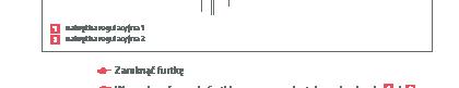
Ustawić furtkę między słupkami
Ustawić furtkę między słupkami
Stellen Sie die Pforte wischen den Pfosten
Wypoziomować i spionizować furtkę
Wypoziomować i spionizować furtkę
Nivellieren Sie die Pforte
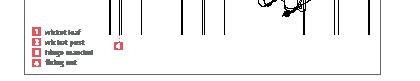
Zaznaczyć miejsca montażu zawiasów do słupków (rysunek 5.)
Zaznaczyć miejsca montażu zawiasów do słupków (rysunek 5.)
Markieren Sie die Orte der Montage von Scharnieren für Pfosten (Abb 5.)
Odłożyć furtkę
Odłożyć furtkę
Das Tor beiseite legen
Osadzić nitonakrętki
Osadzić nitonakrętki
Nietmuttern einbetten
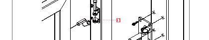
Po wykonaniu otworów pod blachy zawiasowe koniecznie należy wyczyścić pozostałości po wierceniu.
Po wykonaniu otworów pod blachy zawiasowe koniecznie należy wyczyścić pozostałości po wierceniu.
Nach der Herstellung der Löcher für die Scharnierbleche ist es unbedingt notwendig, die Rückstände nach dem Bohren zu reinigen.
Zdjąć blachy zawiasowe i przykręcić do słupka
Zdjąć blachy zawiasowe i przykręcić do słupka
Scharnierbleche entfernen und auf den Pfosten schrauben
10
. 5 .
Abb
10
a b
FRONT
10
a b
FRONT
Wichtig! Nach dem Anheften müssen Sie die Scharniere lösen und alle Späne reinigen, die beim Bohren entstehen.
Wichtig!
Wenn wir das Tor an unebenen Pfosten montieren (z. B. Spaltsteine, andere Materialien), ist es möglich, geklebte Scharniere zu verwenden. Das Scharnierblech hat eine Metallpritze, die mit Hilfe von Klebstoff in das zuvor vorbereitete Loch in der Stange geklebt werden kann.
Montageanleitung Pforte 11
1 Pfortenflügel


2 Pfosten
3 Scharnierschaft
4 Befestigungsmutter
Schieben Sie den Pfortenflügel 1 auf die Scharnierscharfte 3

Achten Sie auf die richtige Anordnung der Pforte (oben/unten)
gleichzeitig auf das untere und obere Scharnier schieben
Setzen Sie Unterlegscheiben und Muttern auf Gewinde 3
Spannkraftmoment 20 Nm
12
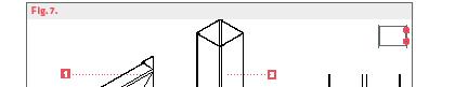
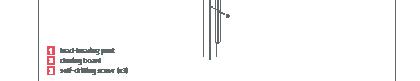
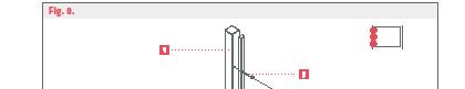
1 Tragpfosten

2 Anschlagleiste
3 selbstbohrende Schraube (x3)


Anschlagleiste an den Anschlagpfosten anbringen 2
die Pforte schliessen
die Zunge des Verschlusses muss mit der Öffnung in der Türleiste übereinstimmen
die Pforte öffnen
Befestigen Sie die Leiste mit Nietmuttern und schrauben Sie die Leiste an den Pfosten
Wichtig!
Nach dem Verschrauben ist es notwendig, die Leiste zu lösen und alle beim Bohren entstandenen Späne zu reinigen.
13
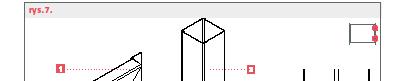
Kurze Leiste: PP001W C CC, PP001L, PP001 N, PP002, PP002P, PP002 P64, PS001, Panel 2D, Panel 3D
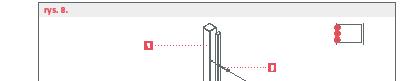
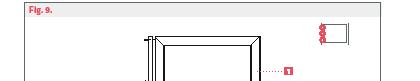
1 Pfortenrahmen


2 Abdeckleiste

Tragen Sie die Abdeckleiste entsprechend den technischen Löchern auf den Pfortenrahmen auf


Schrauben Sie die Leiste
Wichtig!
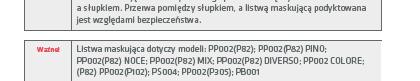
Die Abdeckleiste deckt nicht den gesamten Abstand zwischen dem Pfortenrahmen und dem Pfosten ab. Der Abstand zwischen Pfosten und Abdeckleiste wird aus Sicherheitsgründen diktiert.
Wichtig!
Abdeckleiste gilt für Modelle: PP002(P82); PP002(P82) PINO; PP002(P82) NOCE; PP002(P82) MIX; PP002(P82) DIVERSO; PP002 COLORE; (P82) PP002(P102); PS004; PP002(P305); PB001
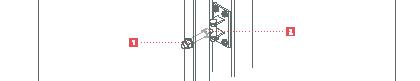
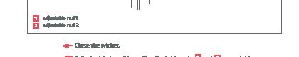
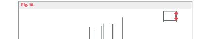
1 Einstellmutter 1


2 Einstellmutter 2

die Pforte schließen
Stellen Sie die Position des Tores mit den Einstellmuttern 1 2 an jedem Scharnier ein
Wichtig! Die Einstellungen immer bei geschlossener Pforte durchführen.
Wichtig! Position des Widerstands in Bezug auf die Pforte einstellen.
15
7 . Lagerung und Transport
7 .1 . Lagerung
Die Schutzfolie sofort nach der Lieferung entfernen.
Senkrecht halten.
An einem trockenen und luftigen Ort aufbewahren.
7 .2 . Transport von Pforten
Die Pforte dürfen nur in vertikaler Position oder auf einem speziellen Gestell für den Transport von großflächigen Elementen transportiert werden.
Schützen Sie alle Oberflächen und Kanten, die während des Transports beschädigt werden können.
Verwenden Sie geeignete Ladevorrichtungen oder sorgen Sie für Unterstützung durch eine ausreichende Anzahl von Personen.
16
8 . Wartung
Eine gut montierte Pforte erfordert keine zusätzlichen Wartungsarbeiten während des Gebrauchs.
Es wird empfohlen, die Pforte einmal im Jahr nach der Wintersaison zur Wartung zu melden.
9 . Entsorgung
Nach dem Gebrauch entsorgen Sie die Produkte von Konsport gemäß den Vorschriften.
Montageanleitung Pforte 17
18
1. Using the manual 19 1.1. Safety instructions .............................. 19 1.2. Other conventions 19 2. Use in accordance with intended purpose ............... 20 3. General information ................................. 21 3.1. General safety guidelines ......................... 21 3.2. Schematic view of the wicket and important definitions 22 4. Delivery content .................................... 23 4.1. Construction elements of the wicket ............... 23 4.2. Fixture ........................................ 23 5. Preparation of strip foundation ........................ 24 6. Wicket assembly .................................... 27 6.1. Assembly of the hinges .......................... 28 6.2. Assembly of the wicket leaf ...................... 30 6.3. Assembly of the closing board..................... 31 6.4. Assembly of the cover strip ....................... 32 6.5. Wicket regulation 33 7. Storage and transport 34 7.1. Storage ........................................ 34 7.2. Wicket transport 34 8. Maintenance 35 9. Disposal 35
Table of contents
1 . Using the manual
1 .1 . Safety instructions
Warning – cautions about minor injuries and property damage.
Safety guideline structure:
Result of a danger
Source of a danger
Warning!
Remedial action
Highlighting of important content:
Important! Important guidelines
1 .2 . Other conventions
1.2.1. Instructions
Structure of instructions: Execute this command. Results description, if applicable.
1.2.2. Lists
List structure with bullets:
First level of list
Second level of list
1.2.3. Keys dimensions elements wicket icon a location where a drawing is applicable
Installation manual Wicket 19
Use in accordance with intended purpose
KONSPORT wickets are intended for fencing of exterior terrains and driveways in private possessions and commercial facilities.
The wickets structure allows for installation of entry phones with electromagnet.
You must not hang unnecessary loads on the wicket. It does not comply with its intended use and damages caused by this are not covered by the warranty.
Important! A specialist sta should assemble the product. Self-assembly results in the lack of warranty for assembly and proper functioning of the wicket.
20 2
.
KONSPORT wickets are products manufactured on the basis of tables of standardised dimensions. This assembly manual presents only rules of the assembly of the wicket made on the basis of standard dimensions. Important parameters of the product are always specified in the order.
The condition of the warranty for assembly and proper functioning is the performance of the assembly by a specialist staff and its confirmation on the protocol of reception (see the manual). Without a signed protocol the warranty covers only manufacturing defects of the product.
Galvanisation is a process that increases resistance of the product to weather conditions. Zinc plating is not a decorative coating. Hot dip galvanising is not a process that raises product aesthetics. Thickenings, slight coarseness of varnished surfaces, which may occur on the products of the manufacturer, is a result of the process of hot dip galvanising and cannot be subject to customer complaints.
It is recommended to order once a year a specialist company to conduct an overview of the wicket. The company should perform necessary repairs, if such need arises. This will guarantee many years of failure-free performance.
3 .1 . General safety guidelines
Damage to the wicket due to improper usage. Hanging loads on the wicket or climbing the wicket may cause damage to the bearing elements of the wicket.
Warning!
Do not load the wicket with any additional weights!
Installation manual Wicket 21
3 . General information
Wicket clearance C – distance between the wicket leaf and a planned level of the bed necessary for free movement of the wicket = 6 cm.


Wicket lumen A – lumen measured between the wicket posts.
22
A B
4 . Delivery content
Installation manual Wicket 23
4 .1 . Construction elements of the wicket 1. Wicket leaf 1 pc. 2. Closing board 1 pc. 3. Load-bearing posts 2 pc. 4 .2 . Fixture 1. Hinges 4 sets 2. Handles 2 sets. 3. Lock (with an insert and a plate) 1 set 4. Assembly screws 1 set 5. Touch-up stick (option) 1 pc. 6. Cover strip (option) 1 pc.
5 . Preparation of strip foundation
Fractured strip foundation. Concrete poured in inadequate weather conditions may crack.
Warning!
While pouring concrete ambient temperature cannot be lower than –5°C.
Important!
For proper casting of strip foundation detailed consulting with the investor is necessary, especially regarding its height and final appearance of the surface under the wicket.
Important!
Important! Trench depth should be adjusted to local conditions of ground freezing.
24
Establish the location of casting the strip foundation 1 .
length of the strip foundation A = wicket clearance E + width of both posts + approx. 20 cm
width of the strip foundation B = 30-40 cm
Dig trench for the strip foundation.
within the line of existing fence
depth of the foundation is min. 1 m

Cast the foundation.
maintain the dimensions A , B and C

use concrete of a class not lower than B20

height of the foundation up to the ground level according to agreements with the investor (e.g. due to a plan of arrangement of paving stone)

25
Dip the closing post of the wicket 2 in the strip foundation.
within the line of the existing fence
height of the post above the ground level is determined by the planed height of the wicket
Repeat the action with the load-bearing post 4

Leave the cast foundation together with the settled load-bearing posts for 14 days until the concrete is congealed.
Important! After fixing the posts check dimensions E and D (Fig. 2)


26
6 . Wicket assembly
After 14 days from casting the strip foundation you may commence the assembly of the wicket.
Important!
A condition of warranty for assembly and proper functioning is a performance of the assembly by a specialist sta and confirmation of it in the protocol of reception (see the manual). Without the signed protocol of reception, the warranty covers only manufacturing defects.
Important!
All drawings show wicket assembly from the perspective of a person standing outside of the premises (acc. to the order). For the needs of presentation assembly drawings show situations from the side of the premises!
Installation manual Wicket 27
Screw hinges to the wicket.
Assemble the hinge by using the hinge mandrel.

Fit the hinge according to the proper direction of hinge fitting in relation to the direction of opening the wicket (Figure 4.).

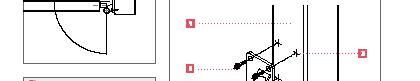

Set the wicket between the posts.
Set the wicket horizontally and vertically.


Mark the spots for fitting the hinges to the posts (Figure 5.).


Put the wicket aside.
Set the threaded inserts.

After making the openings for hinge plates it is necessary to clean the post-drilling remnants.
Remove the hinge plates and screw them to the post.
28
Important!
After screwing, be sure to loosen the hinges and clean off any shavings from drilling.
Important!
When the wicket assembly is performed for uneven posts (e.g. quarry stone, other materials) it is possible to use glued hinges. Hinge plates havea metal rod which can be glued to an opening prepared beforehand.
Installation manual Wicket 29
Slide the wicket leaf 1 on the hinge mandrels 3
Pay attention to the correct wicket position (up/down).

Slide on both upper and lower hinge at the same time.
Put the shims and nuts 4 on the thread 3

Torque of screwing in: 20 Nm

30
Important!
Put the closing board 2 to the closing posto 1 .

Close the wicket.

The lock tail must fit the opening in the closing board.
Open the wicket.
Fix the board with threaded inserts and screw the board to the post.
After screwing in it is necessary to loosen the board and clean all shavings made during drilling.
Short board: PP001W C CC, PP001L, PP001 N, PP002, PP002P, PP002 P64, PS001, Panel 2D, Panel 3D
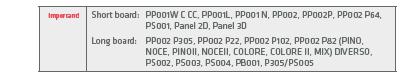
Important!
Long board: PP002 P305, PP002 P22, PP002 P102, PP002 P82 (PINO, NOCE, PINOII, NOCEII, COLORE, COLORE II, MIX) DIVERSO, PS002, PS003, PS004, PB001, P305/PS005
31
Important!
Put the cover strip to the stile according to the technical openings. Screw the strip in.
The cover strip does not cover the entire clearance between the stile and the post. Distance between the post and the cover strip is dictated by safety issues.

Important!

Cover strip applies to models: PP002(P82); PP002(P82) PINO; PP002(P82) NOCE; PP002(P82) MIX; PP002(P82) DIVERSO; PP002 COLORE; (P82) PP002(P102); PS004; PP002(P305); PB001

32
Close the wicket. Adjust wicket position with adjustable nuts 1 and 2 on each hinge.
Important! Always perform adjustments with the wicket closed.
Important! Adjust the resistance position in relation to the wicket.


33
7 .
Storage and transport
7 .1 . Storage
Remove the protective film immediately after delivery.
Store in the vertical and horizontal position.
Store in a dry and ventilated location.
7 .2 . Wicket transport
Wickets should be transported only in vertical positions or on a special frame for transporting of large-surface elements.
Secure all surfaces and edges which are at risk of damage during transport.
Use appropriate loading devices or get the help of an appropriate number of persons.
34
8 . Maintenance
A well assembled wicket does not require any additional maintenance activities during its usage.
It is recommended to order a service overview for the wicket once a year, after winter.
9 . Disposal
After its usage ends, Konsport products should be scrapped according to regulations.
Installation manual Wicket 35
36
Installation manual Wicket 37
Producent zastrzega sobie prawo dokonywania zmian konstrukcyjnych
