CRC Press is an imprint of Taylor & Francis Group, an Informa business
No claim to original U.S. Government works
Printed in the United States of America on acid-free paper
10 9 8 7 6 5 4 3 2 1
International Standard Book Number-13: 978-1-4200-7006-4 (Hardcover)
This book contains information obtained from authentic and highly regarded sources. Reasonable efforts have been made to publish reliable data and information, but the author and publisher cannot assume responsibility for the validity of all materials or the consequences of their use. The authors and publishers have attempted to trace the copyright holders of all material reproduced in this publication and apologize to copyright holders if permission to publish in this form has not been obtained. If any copyright material has not been acknowledged please write and let us know so we may rectify in any future reprint.
Except as permitted under U.S. Copyright Law, no part of this book may be reprinted, reproduced, transmitted, or utilized in any form by any electronic, mechanical, or other means, now known or hereafter invented, including photocopying, microfilming, and recording, or in any information storage or retrieval system, without written permission from the publishers.
For permission to photocopy or use material electronically from this work, please access www.copyright.com (http://www.copyright.com/) or contact the Copyright Clearance Center, Inc. (CCC), 222 Rosewood Drive, Danvers, MA 01923, 978-750-8400. CCC is a not-for-profit organization that provides licenses and registration for a variety of users. For organizations that have been granted a photocopy license by the CCC, a separate system of payment has been arranged.
Trademark Notice: Product or corporate names may be trademarks or registered trademarks, and are used only for identification and explanation without intent to infringe.
Library of Congress Cataloging-in-Publication Data
Das, Braja M., 1941Shallow foundations bearing capacity and settlement / Braja M. Das. -- 2nd ed. p. cm.
Includes bibliographical references and index.
ISBN 978-1-4200-7006-4 (hardcover : alk. paper)
1. Foundations. 2. Settlement of structures. 3. Soil mechanics. I. Title.
TA775.D2275 2009 624.1’5--dc22 2009000683
Visit the Taylor & Francis Web site at http://www.taylorandfrancis.com
and the CRC Press Web site at http://www.crcpress.com
Dedication
Toourgranddaughter,ElizabethMadison
2.13
3.2
3.2.1
3.2.2
3.2.3
3.3
5.3
5.4
5.4.1
5.4.2
5.4.3
5.4.4
5.4.4.1
5.4.4.2
5.4.4.3
5.4.4.4
5.4.5
5.4.6
5.4.7
5.4.8
7.2.4
7.2.5
7.3.3
8.3.4
Preface
ShallowFoundations:BearingCapacityandSettlement was originally published with a 1999 copyright and was intended for use as a reference book by university faculty members and graduate students in geotechnical engineering as well as by consulting engineers. During the last ten years, the text has served that constituency well. More recently there have been several requests to update the material and prepare a new edition. This edition of the text has been developed in response to those requests.
The text is divided into eight chapters. Chapters 2, 3, and 4 present various theories developed during the past 50 years for estimating the ultimate bearing capacity of shallow foundations under various types of loading and subsoil conditions. In this edition new details relating to the variation of the bearing capacity factor Ng published more recently have been added and compared in Chapter 2. This chapter also has a broader overview and discussion on shape factors as well as scale effects on the bearing capacity tests conducted on granular soils. Ultimate bearing capacity relationships for shallow foundations subjected to eccentric and inclined loads have been added in Chapter 3. Published results of recent laboratory tests relating to the ultimate bearing capacity of square and circular foundations on granular soil of limited thickness underlain by a rigid rough base have been included in Chapter 4.
Chapter 5 discusses the principles for estimating the settlement of foundations— both elastic and consolidation. Westergaard’s solution for stress distribution caused by a point load and uniformly loaded flexible circular and rectangular areas has been added. Procedures to estimate the elastic settlement of foundations on granular soil have been fully updated and presented in a rearranged form. These procedures include those based on the correlation with standard penetration resistance, strain influence factor, and the theory of elasticity.
Chapter 6 discusses dynamic bearing capacity and associated settlement. Also included in this chapter are some details regarding permanent foundation settlement due to cyclic and transient loadings derived from experimental observations obtained from laboratory and field tests.
During the past 25 years, steady progress has been made to evaluate the possibility of using reinforcement in granular soil to increase the ultimate and allowable bearing capacities of shallow foundations and also to reduce their settlement under various types of loading conditions. The reinforcement materials include galvanized steel strips and geogrids. Chapter 7 presents the state of the art on this subject.
Shallow foundations (such as transmission tower foundations) are on some occasions subjected to uplifting forces. The theories relating to the estimations of the ultimate uplift capacity of shallow foundations in granular and clay soils are presented in Chapter 8.
Example problems to illustrate the theories are given in each chapter.
I am grateful to my wife, Janice, for typing the manuscript and preparing the necessary artwork.
About the Author
Professor Braja M. Das received his Ph.D. in geotechnical engineering from the University of Wisconsin, Madison, USA. In 2006, after serving 12 years as dean of the College of Engineering and Computer Science at California State University, Sacramento, Professor Das retired and now lives in the Las Vegas, Nevada, area.
A fellow and life member in the American Society of Civil Engineers (ASCE), Professor Das served on the ASCE’s Shallow Foundations Committee, Deep Foundations Committee, and Grouting Committee. He was also a member of the ASCE’s editorial board for the JournalofGeotechnicalEngineering. From 2000 to 2006, he was the coeditor of GeotechnicalandGeologicalEngineeringAn InternationalJournal published by Springer in the Netherlands. Now an emeritus member of the Committee of Chemical and Mechanical Stabilization of the Transportation Research Board of the National Research Council of the United States, he served as committee chair from 1995 to 2001. He is also a life member of the American Society for Engineering Education. He was recently named the editor-in-chief of a new journal—the InternationalJournalofGeotechnical Engineering —published by J. Ross Publishing of Florida (USA). The first issue of the journal was released in October 2007.
Dr. Das has received numerous awards for teaching excellence. He is the author of several geotechnical engineering text and reference books and has authored numerous technical papers in the area of geotechnical engineering. His primary areas of research include shallow foundations, earth anchors, and geosynthetics.
1 Introduction
1.1 Shallow FoundationS—General
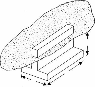
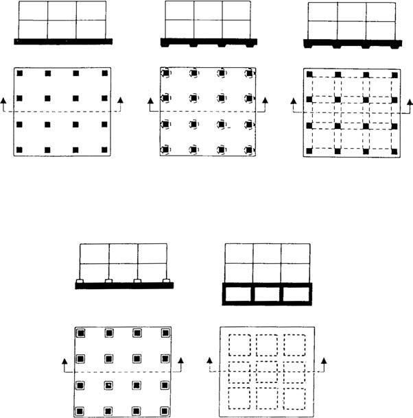
The lowest part of a structure that transmits its weight to the underlying soil or rock is the foundation. Foundations can be classified into two major categories—shallow foundations and deepfoundations. Individual footings (Figure 1.1), square or rectangular in plan, that support columns and strip footings that support walls and other similar structures are generally referred to as shallow foundations. Matfoundations, also considered shallow foundations, are reinforced concrete slabs of considerable structural rigidity that support a number of columns and wall loads. Several types of mat foundations are currently used. Some of the common types are shown schematically in Figure 1.2 and include
1. Flat plate (Figure 1.2a). The mat is of uniform thickness.
2. Flat plate thickened under columns (Figure 1.2b).
3. Beams and slab (Figure 1.2c). The beams run both ways, and the columns are located at the intersections of the beams.
4. Flat plates with pedestals (Figure 1.2d).
5. Slabs with basement walls as a part of the mat (Figure 1.2e). The walls act as stiffeners for the mat.
When the soil located immediately below a given structure is weak, the load of the structure may be transmitted to a greater depth by piles and drilledshafts, which are considered deepfoundations. This book is a compilation of the theoretical and experimental evaluations presently available in the literature as they relate to the load-bearing capacity and settlement of shallow foundations.
The shallow foundation shown in Figure 1.1 has a width B and a length L. The depth of embedment below the ground surface is equal to Df . Theoretically, when B/L is equal to zero (that is, L = ∞), a plane strain case will exist in the soil mass supporting the foundation. For most practical cases, when B/L ≤ 1/5 to 1/6, the plane strain theories will yield fairly good results. Terzaghi1 defined a shallow foundation as one in which the depth Df is less than or equal to the width B (Df /B ≤ 1). However, research studies conducted since then have shown that Df /B can be as large as 3 to 4 for shallow foundations.
1.2 typeS oF Failure in Soil at ultimate load
Figure 1.3 shows a shallow foundation of width B located at a depth of Df below the ground surface and supported by dense sand (or stiff, clayey soil). If this foundation is subjected to a load Q that is gradually increased, the load per unit area, q = Q/A
FiGure 1.1 Individual footing.
FiGure 1.2 Various types of mat foundations: (a) flat plate; (b) flat plate thickened under columns; (c) beams and slab; (d) flat plate with pedestals; (e) slabs with basement walls.
(A = area of the foundation), will increase and the foundation will undergo increased settlement. When q becomes equal to qu at foundation settlement S = Su, the soil supporting the foundation undergoes sudden shear failure. The failure surface in the soil is shown in Figure 1.3a, and the q versus S plot is shown in Figure 1.3b. This type of failure is called a generalshearfailure, and qu is the ultimatebearingcapacity. Note that, in this type of failure, a peak value of q = qu is clearly defined in the loadsettlement curve.
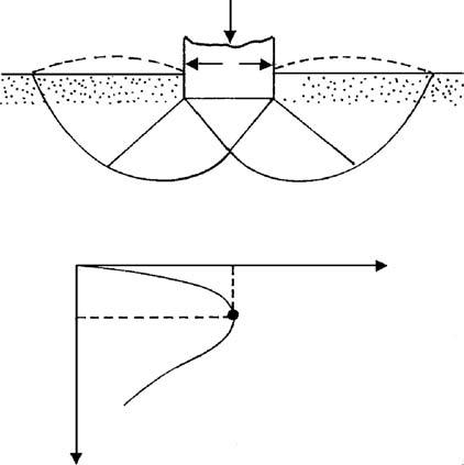
If the foundation shown in Figure 1.3a is supported by a medium dense sand or clayey soil of medium consistency (Figure 1.4a), the plot of q versus S will be as shown in Figure 1.4b. Note that the magnitude of q increases with settlement up to q = q ′ u, and this is usually referred to as the firstfailureload.2 At this time, the developed failure surface in the soil will be as shown by the solid lines in Figure 1.4a. If the load on the foundation is further increased, the load-settlement curve becomes steeper and more erratic with the gradual outward and upward progress of the failure surface in the soil (shown by the jagged line in Figure 1.4b) under the foundation. When q becomes equal to qu (ultimate bearing capacity), the failure surface reaches the ground surface. Beyond that, the plot of q versus S takes almost a linear shape, and a peak load is never observed. This type of bearing capacity failure is called a localshearfailure.
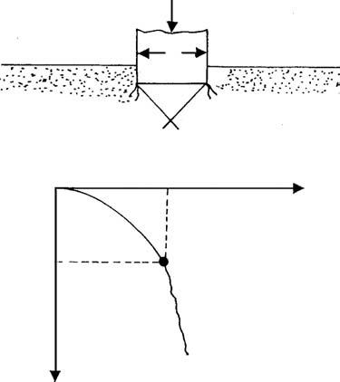
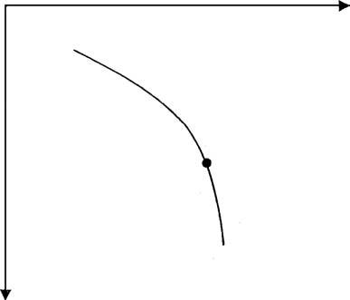
Figure 1.5a shows the same foundation located on a loose sand or soft clayey soil. For this case, the load-settlement curve will be like that shown in Figure 1.5b. A peak value of load per unit area q is never observed. The ultimate bearing capacity qu is
FiGure 1.3 General shear failure in soil.
FiGure 1.4 Local shear failure in soil.
FiGure 1.5 Punching shear failure in soil.
/γB (log scale) S / B (%)—(log scale)
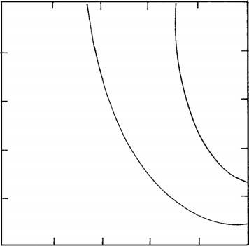
defined as the point where ΔS/Δq becomes the largest and remains almost constant thereafter. This type of failure in soil is called a punchingshearfailure. In this case the failure surface never extends up to the ground surface. In some cases of punching shear failure, it may be difficult to determine the ultimate load per unit area qu from the q versus S plot shown in Figure 1.5. DeBeer3 recommended a very consistent ultimate load criteria in which a plot of log q/gB versus log S/B is prepared (g = unit weight of soil). The ultimate load is defined as the point of break in the log−log plot as shown in Figure 1.6.
The nature of failure in soil at ultimate load is a function of several factors such as the strength and the relative compressibility of the soil, the depth of the foundation (Df) in relation to the foundation width B, and the width-to-length ratio (B/L) of the foundation. This was clearly explained by Vesic,2 who conducted extensive laboratory model tests in sand. The summary of Vesic’s findings is shown in a slightly different form in Figure 1.7. In this figure Dr is the relative density of sand, and the hydraulic radius R of the foundation is defined as
A = area of the foundation = BL P = perimeter of the foundation = 2(B + L)
Ultimate load
FiGure 1.6 Nature of variation of q/g B with S/B in a log-log plot.
1.7
for a square foundation B = L. So,
= 4
From Figure 1.7 it can be seen that when Df /R ≥ about 18, punching shear failure occurs in all cases irrespective of the relative density of compaction of sand.
1.3 Settlement at ultimate load
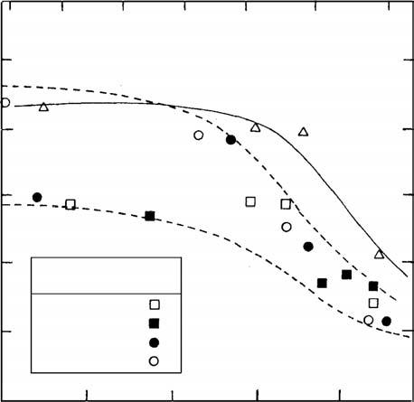
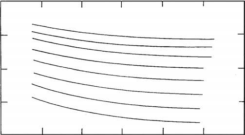
The settlement of the foundation at ultimate load S u is quite variable and depends on several factors. A general sense can be derived from the laboratory model test results in sand for surface foundations ( D f / B = 0) provided by Vesic 4 and which are presented in Figure 1.8. From this figure it can be seen that, for any given foundation, a decrease in the relative density of sand results in an increase in the settlement at ultimate load. DeBeer 3 provided laboratory test results of circular surface foundations having diameters of 38 mm, 90 mm, and 150 mm on sand at various relative densities ( D r ) of compaction. The results of these tests are summarized in Figure 1.9. It can be seen that, in general, for granular soils the settlement at ultimate load S u increases with the increase in the width of the foundation B .
Based on laboratory and field test results, the approximate ranges of values of Su in various types of soil are given in Table 1.1.
(kN/m 3) Circular
FiGure 1.8 Variation of S B u for surface foundation D B f = () 0 on sand. Source: From Vesic, A. S. 1973. Analysis of ultimate loads on shallow foundations. J. Soil Mech. Found. Div., ASCE, 99(1): 45.
FiGure 1.9 DeBeer’s laboratory test results on circular surface foundations on sand—variation of S B u with γB pa and Dr Note: B = diameter of circular foundation; p a = atmospheric pressure ≈100 kN/m 2; g = unit weight of sand.
table 1.1
approximate ranges of Su
Soil
Sand 0 5–12
Sand Large25–28
Clay 04–8
Clay Large15–20
1.4 ultimate and allowable bearinG CapaCitieS
For a given foundation to perform to its optimum capacity, one must ensure that the load per unit area of the foundation does not exceed a limiting value, thereby causing shear failure in soil. This limiting value is the ultimate bearing capacity qu. Considering the ultimate bearing capacity and the uncertainties involved in evaluating the shear strength parameters of the soil, the allowable bearing capacity qall can be obtained as
A factor of safety of three to four is generally used. However, based on limiting settlement conditions, there are other factors that must be taken into account in deriving the allowable bearing capacity. The total settlement St of a foundation will be the sum of the following:
1. Elastic, or immediate, settlement Se (described in section 1.3), and
2. Primary and secondary consolidation settlement Sc of a clay layer (located below the groundwater level) if located at a reasonably small depth below the foundation.
Most building codes provide an allowable settlement limit for a foundation, which may be well below the settlement derived corresponding to qall given by equation (1.4). Thus, the bearing capacity corresponding to the allowable settlement must also be taken into consideration.
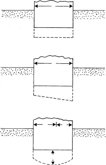
A given structure with several shallow foundations may undergo uniform settlement (Figure 1.10a). This occurs when a structure is built over a very rigid structural mat. However, depending on the loads on various foundation components, a structure may experience differentialsettlement. A foundation may undergo uniform tilt (Figure 1.10b) or nonuniform settlement (Figure 1.10c). In these cases, the angular
(min)
(a) Uniform settlement
(max)
(b) Uniform tilt
(min)
(max)
(c) Nonuniform settlement
FiGure 1.10 Settlements of a structure.
distortion Δ can be defined as
Limits for allowable differential settlements of various structures are also available in building codes. Thus, the final decision on the allowable bearing capacity of a foundation will depend on (a) the ultimate bearing capacity, (b) the allowable settlement, and (c) the allowable differential settlement for the structure.
reFerenCeS
1. Terzaghi, K. 1943. TheoreticalSoilMechanics. New York: Wiley.
2. Vesic, A. S. 1973. Analysis of ultimate loads on shallow foundations. J.SoilMech. Found.Div., ASCE, 99(1): 45.
3. DeBeer, E. E. 1967. Proefondervindelijke bijdrage tot de studie van het gransdraagvermogen van zand onder funderingen op staal, Bepaling von der vormfactor sb. Annales desTravauxPublicsdeBelgique 6: 481.
4. Vesic, A. S. 1963. Bearing capacity of deep foundations in sand. HighwayRes.Rec., National Research Council, Washington, D.C. 39:12.
Over the last 60 years, several bearing capacity theories for estimating the ultimate bearing capacity of shallow foundations have been proposed. This chapter summarizes some of the important works developed so far. The cases considered in this chapter assume that the soil supporting the foundation extends to a great depth and also that the foundation is subjected to centric vertical loading. The variation of the ultimate bearing capacity in anisotropic soils is also considered.
2.2 terzaGhi’S bearinG CapaCity theory
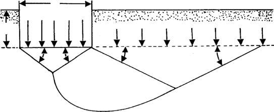
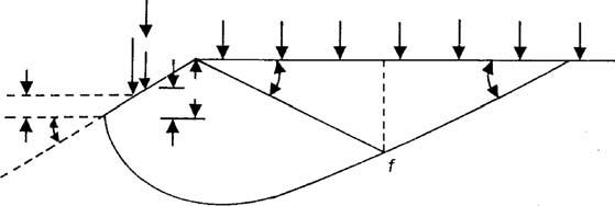
In 1948 Terzaghi1 proposed a well-conceived theory to determine the ultimate bearing capacity of a shallow, rough, rigid, continuous (strip) foundation supported by a homogeneous soil layer extending to a great depth. Terzaghi defined a shallow foundation as a foundation where the width B is equal to or less than its depth Df. The failure surface in soil at ultimate load (that is, qu per unit area of the foundation) assumed by Terzaghi is shown in Figure 2.1. Referring to Figure 2.1, the failure area in the soil under the foundation can be divided into three major zones:
1. Zone abc. This is a triangular elastic zone located immediately below the bottom of the foundation. The inclination of sides ac and bc of the wedge with the horizontal is a = f (soil friction angle).
2. Zone bcf. This zone is the Prandtl’s radial shear zone.
3. Zone bfg. This zone is the Rankinepassivezone. The sliplines in this zone make angles of ± (45 f/2) with the horizontal.
Note that a Prandtl’s radial shear zone and a Rankine passive zone are also located to the left of the elastic triangular zone abc; however, they are not shown in Figure 2.1.
Line cf is an arc of a logspiral and is defined by the equation
Lines bf and fg are straight lines. Line fg actually extends up to the ground surface. Terzaghi assumed that the soil located above the bottom of the foundation could be replaced by a surcharge q = g Df
Soil
Unit weight = γ
Cohesion = c
Friction angle = φ
FiGure 2.1 Failure surface in soil at ultimate load for a continuous rough rigid foundation as assumed by Terzaghi.
The shear strength of the soil can be given as
where s ′ = effective normal stress c = cohesion
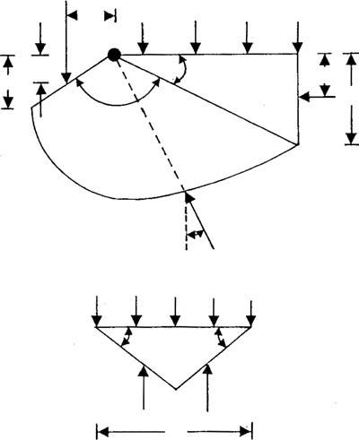
The ultimate bearing capacity qu of the foundation can be determined if we consider faces ac and bc of the triangular wedge abc and obtain the passive force on each face required to cause failure. Note that the passive force Pp will be a function of the surcharge q = g Df, cohesion c, unit weight g, and angle of friction of the soil f. So, referring to Figure 2.2, the passive force Pp on the face bc per unit length of the foundation at a right angle to the cross section is
qp
+
(2.3) where Ppq, Ppc, and Ppg = passive force contributions of q, c, and g, respectively
FiGure 2.2 Passive force on the face bc of wedge abc shown in Figure 2.1.
FiGure 2.3 Determination of Ppq (f ≠ 0, g = 0, q ≠ 0, c = 0).
It is important to note that the directions of Ppq, Ppc, and Ppg are vertical since the face bc makes an angle f with the horizontal, and Ppq, Ppc, and Ppg must make an angle f to the normal drawn to bc. In order to obtain Ppq, Ppc, and Ppg , the method of superposition can be used; however, it will not be an exact solution.
2.2.1 Relationship foR Ppq (f ≠ 0, g = 0, q ≠ 0, c = 0)
Consider the free body diagram of the soil wedge bcfj shown in Figure 2.2 (also shown in Figure 2.3). For this case, the center of the log spiral (of which cf is an arc) will be at point b. The forces perunitlengthofthewedgebcfj due to the surcharge q only are shown in Figure 2.3a, and they are
1. Ppq
2. Surcharge q
3. The Rankine passive force Pp(1)
4. The frictional resisting force F along the arc cf The Rankine passive force Pp(1) can be expressed as
Shallow Foundations: Bearing Capacity and Settlement
According to the property of a log spiral defined by the equation r = r0eqtanf, the radial line at any point makes an angle f with the normal; hence, the line of action of the frictional force F will pass through b (the center of the log spiral as shown in Figure 2.3a). Taking the moment of all forces about point b:
From equation (2.1):
Combining equations (2.4), (2.5), (2.8), and (2.9):
Now, combining equations (2.6), (2.7), and (2.10):
Considering the stability of the elastic wedge abc under the foundation as shown in Figure 2.3b
qBP qpq ()×=12 where qq = load per unit area on the foundation, or q
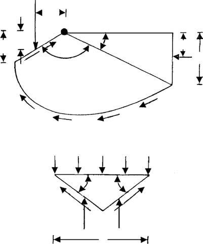
2.2.2 Relationship foR Ppc (f ≠ 0, g = 0, q = 0, c ≠ 0)
Figure 2.4 shows the free body diagram for the wedge bcfj (also refer to Figure 2.2). As in the case of Ppq, the center of the arc of the log spiral will be located at point b The forces on the wedge, which are due to cohesion c, are also shown in Figure 2.4, and they are
1. Passive force Ppc
2. Cohesive force Ccbc=×() 1
FiGure 2.4 Determination
3. Rankine passive force due to cohesion
4. Cohesive force per unit area c along arc cf
Taking the moment of all the forces about point b
The relationships for Hd , r0 , and r1 in terms of B and f are given in equations (2.9), (2.6), and (2.7), respectively. Combining equations (2.6), (2.7), (2.9), and (2.15), and noting that sin2 (45 − f/2) × tan (45 + f/2) = ½ cos f,
or
Considering the equilibrium of the soil wedge abc (Figure 2.4b):
where
qc = load per unit area of the foundation
Combining equations (2.16) and (2.17):
However,
Also,
Substituting equations (2.20) and (2.21) into equation (2.19)
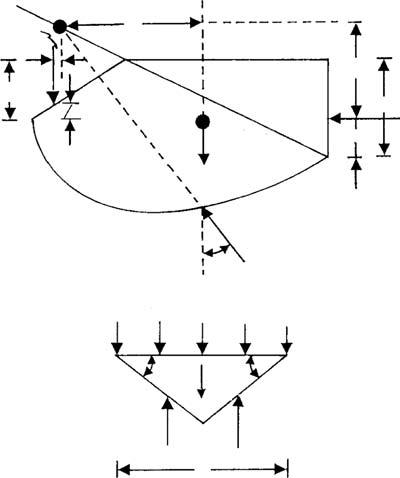
2.2.3 Relationship foR
Figure 2.5a shows the free body diagram of wedge bcfj. Unlike the free body diagrams shown in Figures 2.3 and 2.4, the center of the log spiral of which bf is an arc is at a point O along line bf and not at b. This is because the minimum value of Ppg has to be determined by several trials. Point O is only one trial center. The forces per unit length of the wedge that need to be considered are
1. Passive force Ppg
2. The weight W of wedge bcfj
3. The resultant of the frictional resisting force F acting along arc cf
4. The Rankine passive force Pp(3)
The Rankine passive force Pp(3) can be given by the relation
FiGure 2.5 Determination of
Also note that the line of action of force F will pass through O. Taking the moment of all forces about O:
or
If a number of trials of this type are made by changing the location of the center of the log spiral O along line bf, then the minimum value of Ppg can be determined. Considering the stability of wedge abc as shown in Figure 2.5, we can write that
where qg = force per unit area of the foundation Ww = weight of wedge abc
The passive force Ppg can be expressed in the form
where Kpg = passive earth pressure coefficient
Substituting equation (2.28) into equation (2.27)
2.2.4 Ultimate BeaRing CapaCity
The ultimate load per unit area of the foundation (that is, the ultimate bearing capacity qu) for a soil with cohesion, friction, and weight can now be given as
Substituting the relationships for qq, qc, and qg given by equations (2.12), (2.22), and (2.29) into equation (2.30) yields
where Nc, Nq, and Ng = bearing capacity factors, and
Table 2.1 gives the variations of the bearing capacity factors with soil friction angle f given by equations (2.32), (2.33), and (2.34). The values of Ng were obtained by Kumbhojkar.2
Krizek3 gave simple empirical relations for Terzaghi’s bearing capacity factors Nc, Nq, and Ng with a maximum deviation of 15%. They are as follows:
where
f = soil friction angle, in degrees
Equations (2.35a), (2.35b), and (2.35c) are valid for f = 0 to 35°. Thus, substituting equation (2.35) into (2.31),
For foundations that are rectangular or circular in plan, a plane strain condition in soil at ultimate load does not exist. Therefore, Terzaghi1 proposed the following relationships for square and circular foundations:
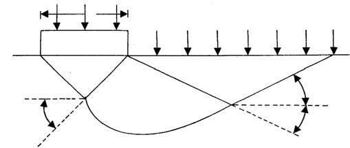
Since Terzaghi’s founding work, numerous experimental studies to estimate the ultimate bearing capacity of shallow foundations have been conducted. Based on these studies, it appears that Terzaghi’s assumption of the failure surface in soil at ultimate load is essentially correct. However, the angle a that sides ac and bc of the wedge (Figure 2.1) make with the horizontal is closer to 45 + f/2 and not f, as assumed by Terzaghi. In that case, the nature of the soil failure surface would be as shown in Figure 2.6.
The method of superposition was used to obtain the bearing capacity factors Nc, Nq, and Ng . For derivations of Nc and Nq, the center of the arc of the log spiral cf is located at the edge of the foundation. That is not the case for the derivation of Ng . In effect, two different surfaces are used in deriving equation (2.31); however, it is on the safe side.
2.1
45 + φ/2
45 – φ/2
45 – φ/2
FiGure 2.6 Modified failure surface in soil supporting a shallow foundation at ultimate load.
2.3 terzaGhi’S bearinG CapaCity theory For loCal Shear Failure
It is obvious from section 2.2 that Terzaghi’s bearing capacity theory was obtained assuming general shear failure in soil. However, Terzaghi1 suggested the following relationships for local shear failure in soil:
Strip foundation (B/L = 0; L = length of foundation):
Square foundation (B = L):
Circular foundation (B = diameter):
where ′′ ′ NNN cq,, and γ = modified bearing capacity factors c ′ = 2c/3
The modified bearing capacity factors can be obtained by substituting f′ = tan-1(0.67 tan f) for f in equations (2.32), (2.33), and (2.34). The variations of ′′ ′ NNN cq,, and γ with f are shown in Table 2.2.
Vesic4 suggested a better mode to obtain f′ for estimating ′ N c and ′ N q for foundations on sand in the forms