
2 minute read
International Journal for Research in Applied Science & Engineering Technology (IJRASET)

from Quality Improvement of Oil and Fuel Leakage in Diesel Engine by using Semi Automatic Setup
by IJRASET


ISSN: 2321-9653; IC Value: 45.98; SJ Impact Factor: 7.538
Advertisement
Volume 11 Issue III Mar 2023- Available at www.ijraset.com
The problem was Engineer will not able to test leakage easily due to overheating of engine joints in fuel line and oil leakage from the engine because these problems are not easily detectable. This method was not 100% leak detectable. So instead of dispatching engine to application department it was rejected from testing to assembly for rework on the leakage. Loss of time & cost of engine for rework reduces companies profit & productivity with no customer satisfaction.
III. METHODOLOGY
The semi-automatic set up includes ATEQ D520 unit & air pressure regulator for finding out leakage quantity. The ATEQ D520 is a flow meter which measures a drop in pressure with a differential sensor (transducer).
Flow chart of air supply
IV. EXPERIMENTAL SETUP
The setup consists of ATEQ D520 sensor, Pressure regulator, Air and Fuel line connections for oil and fuel leakage testing. Pressurized air at 1 bar is supplied into the engine through Breather plug & overflow pipe. Supply of air will be 30 seconds stabilization time. If pressure doesn't drops (within 20 seconds) engine is ok and no leak found indicated by green light. If pressure gets dropped in fuel line, engine will get rejected that means engine is not ok & ATEQ D520 indicates Red light. So engine leakage testing is done by spraying soap water on that leak portion due to which bubbles May come out which will indicate leakage at that point.

ISSN: 2321-9653; IC Value: 45.98; SJ Impact Factor: 7.538
Volume 11 Issue III Mar 2023- Available at www.ijraset.com
V. PRINCIPLE OF A CYCLE
The ATEQ D520 is a flow meter which measures a drop in pressure with a differential sensor (transducer) which is placed at the extremities of a calibrated flow tube. When fluid(air) moves through a calibrated flow tube (laminar flow), a drop in pressure occurs, the value of which is proportional to flow.
VI. SEQUENCE OF OPERATION
1) Assembled engines from the trolleys of the line conveyor will come for the leak testing on leak test station for every90 seconds
2) Operator has to select air circuit on selector switch provided on set up
3) Operator can see the respective program on ATEQ D520 sensor which is provided by that ATEQ Company
4) Remove the rocker cover with the gasket on which breather hole is there
5) Mount standard rocker cover gauge made to fill air into the engine one supply of airline is given tobreather plug hole & other is given to fuel line through overflow pipe
6) Deep stick is inserted which measures oil level of engine Oil filter bolt is tightened
7) Now there is no any phenomenon from where leakage will occur, start the cycle
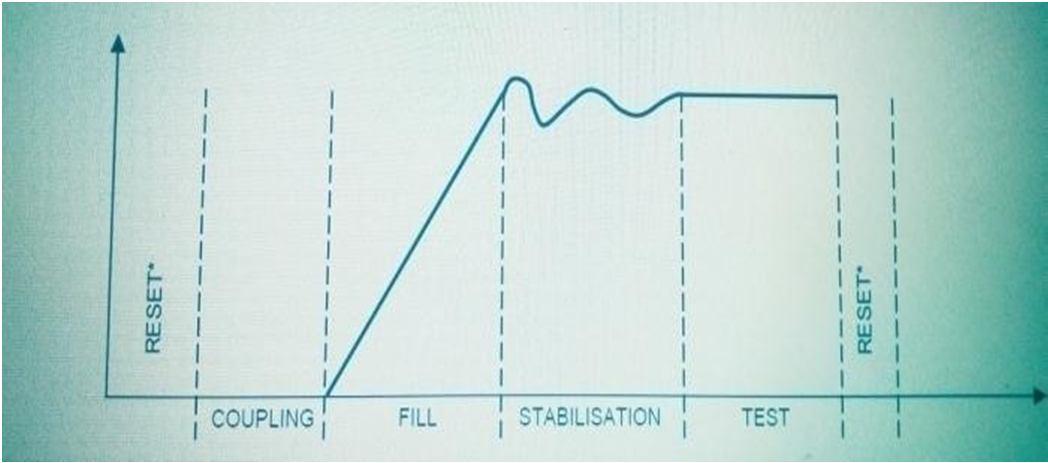
8) ATEQ will start Air leak testing cycle- Start, The filltime, the stabilization Time, The test time, Reset, End of Cycle.

9) ATEQ will give results Ok or Not Ok depending on leakage found or not & the indication of this Ok or Not Ok is presented on lamp
10) Green light indicates the engine is Ok i.e.no leakage found in the engine. Red light indicate engine is not ok i.e. leakage phenomenon occurred in the engine. mark Ok or Not Ok on engine
11) Leakage may be from Governor Support O-ring, oil pan, PTO (power take off), push rod tube rubber bush, various Banjo joints of fuel line.
12) Remove all the plugs from the engine & send enginefor next station for next operation i.e. Inspection. Repeat this cycle for next engine

