MEFI Fuel Injection
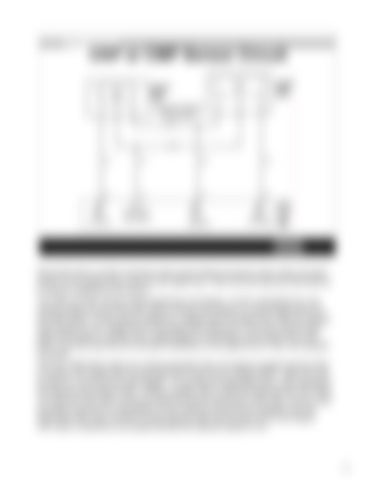
CKP or CMP Sensor Circuit
Remember that a number of sensors share power feeds and sensor return wires, but each sensor on the engine has to have its own signal wire. That is the wire that the ECM looks at to receive a signal from the sensor. The CMP and CKP sensors share DepsPower and DepsLo. As the crankshaft turns, the reluctor passes the tip of the CKP sensor and the cam reluctor (or vane) passes the tip of the CMP sensor. As the reluctor passes by, voltage enters the signal wire. After the reluctor tooth passes by, the voltage level on the signal wire drops to 0V. So as the reluctor teeth pass by the sensor a square wave voltage signal is transmitted up the signal wire to the ECM. The ECM uses the A/D converter (voltmeter) on the signal wire to “see” and interpret the signal. CKP and CMP faults codes are usually generated when one signal is present and the other is missing. CKP signal input can be seen with a scan tool as “Engine RPM”. CMP input can be seen on a scan tool as “Cam Retard”. To use these as diagnostic tools, crank the engine and observe the “Engine RPM”. If RPM is greater than 0, then the ECM sees the CKP input. To check the CMP input, crank the engine and ensure that there is CKP input. As you crank the engine now look at “Cam Retard”, if cam retard is moving off of 0 degrees, then the ECM sees CMP input. No MEFI 4 ECM requires CMP input to start and run the engine. CKP input is required for any Speed Density fuel injection system to run.
69


