5 minute read
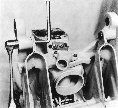
Intermediate housing

from Volvo Penta 280, 280-DP, 285, 290, 290-DP SP-A, SP-C, DP-A, DP-B, DP-C Drives Workshop Manual - PDF

Reconditioning the intermediate housing, model 280 and 285
884259
8.
Remove the shaft journals (48). Remove the spring (57), the spring (49) and the springs (58).
NOTE! Hold the spring shaft (50). Remove the nuts (55) and the spring catches (52) and (54) and the spacer washers (44) and the retaining pawl (42). Lift out the bearing (43) and the shaft (53) and the push rod (45). Wash the parts and check for wear. Replace parts if necessary.
Assembly
Oil all moving parts and the screws prior to assembly.
10. Paint the retaining pawl with a thin layer of ‘touch-up paint’. Painting is hard to do when the pawl is assembled.
The picture reflects an assembled retaining pawl.
884259
9. Install the shaft (53) on one of the retaining pawls (42) and the spacer washer (44) and the spring catch (52). Install one of the nuts (55) on the shaft. Then place the push rod (45) on the stop shaft (56) and insert the bearing (43) in the retaining pawl half. Then install the remaining retaining pawl (42) and the spring catches (54) along with the spacer washer (44) on the shaft (53) and the bearing (43). Install the remaining nut (55).
NOTE! Tighten the nuts (55) completely. Then ease them off approx. 1/8 turn in order to make the spring catches movable without adding a play. Then install the locking yoke (47) and the shaft journals (48) along with the spring (57) and the washer (51) in the bearing (43). Install the spring shaft (50) with the assistance of the springs (58) and install the spring (49) between the bearing (43) and the stop shaft (56).
11. Grease the needle bearing (1) with an universal type of grease and press it into the center of the yoke. Use special tool 884259 and 9991801. Turn the bearing in a way that the tool is pressing against the side where the material is at the thickest, (where the text is stamped into the material).
12. Press in both sealing rings. Use special tool 884259
NOTE! The sealing rings are to seal against water and thus have to be installed ”facing” each other.
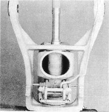
14. Install the retaining pawl in the yoke and place the yoke with the retaining pawl in its location in the intermediate housing.
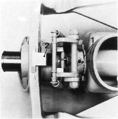
NOTE! Insert the wear washer (1) between the lower attachment of the yoke and the intermediate housing and the two plastic washers (2) with one on each side of the bearing. Then press in the steering spindle until the collar bottoms. Be very careful during the installation of the steering spindle in order to avoid damaging the lower sealing ring.
13. Glue the bushing to the yoke. Use bushing installation adhesive, Volvo Penta part no. 11161351-0 or Loctite® 603 . The flange must be turned downwards against the retaining pawl.
15. Install the hose connection with its gasket on the yoke. Coat the sealing surfaces with sealing compound, Volvo Penta part no. 1161099-5 or Permatex® no. 3.
NOTE! On sterndrive model 280 the hose connection must be pointing straight forwards.
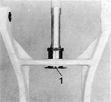
16. Install the shift yoke (3) and push in the shaft (2) and lock it with the cotter pin (1).
NOTE! A washer must be installed on either side of the cotter pin.
Reconditioning the intermediate housing, model 290 and 290A
1. Remove the 2 screws holding the hose connection. Remove the hose connection and the gasket.
9991801
884311
2. Remove the yoke by driving out the steering spindle. Use special tools 884311 and 9991801. Lift up the attachment device of the trim cylinders and remove the retaining pawl, the two wear washers, the plastic washer and the guide washer from the steering yoke.
5. Should the shift yoke be in need of being replaced, remove the cotter pin (1). Then pull out the shaft (2) and remove the shift yoke (3).
3. Press out the sealing rings and the needle bearing. Use special tools 884259 and 9991801.
NOTE! There is a sealing ring on each side of the needle bearing.
4. Press out the bushing. Use special tools 884259 and 9991801
6. Remove the bearing race of the axial bearing. Use special tools 884140 and 884143. Also replace the O-rings (1). One in each end of the oil tube.
7. If necessary the retaining pawl is dismantled as follows:
Remove the shaft journals (42). Remove the spring (43) the spring (40) and the springs (44).
NOTE! Hold the spring shaft (45). Remove the nuts (38) and spring catches (34) and (37) and the spacer washers (36) as well as the retaining pawl (33). Remove the bearing (32) and the shaft (35). Clean the parts and check for wear. Replace parts if necessary.
Assembly
Oil all moving parts and the screws prior to assembly.
8. Install the shaft (35, picture above) on one of the retaining pawls (33) and install the spacer washer (36) and the spring catch (34). Install one of the nuts (38) on the shaft. Then place the stop shaft (39) and the bearing (32) in the retaining pawl half. Then install the remaining retaining pawl (33) and the spring catch (37) the spacer sleeve (36) on the shaft (35) and the bearing (32). Install the second nut (38).
NOTE! Tighten the nuts (38) completely. Then ease off a 1/8 turn to allow the spring catches to move without adding a play. Then install the locking yoke (41) and the shaft journals (42) with the spring (43) and the washer (46) in the bearing (32). Install the spring shaft (45) in its location with the assistance of the springs (44) and install the spring (40) between the bearing (32) and the stop shaft (39).
9. Paint the retaining pawl with a thin layer of ”touch-up paint”. Painting is hard to do when the pawl is assembled.
The picture reflects an assembled retaining pawl.
9991801 884259
10. Grease the needle bearing with an universal type of grease and press it into the center of the yoke. Use special tools 884259 and 9991801. Turn the bearing in a way that the tool is pressing against the side where the material is at the thickest (where the text is stamped into the material).
11. Press in both sealing rings. Use special tool 884259
NOTE! The sealing rings are to seal against water and thus have to be installed ”facing” each other.
13. Place the yoke and the wear washer (1) on the intermediate housing and push in the steering spindle (2) as far as to hold the wear washer.
NOTE! Be careful not to damage the lower sealing rings.
12. Press the bushing into the yoke. Use special tool 884259 and 9991801.
14. Insert the retaining pawl into the intermediate housing. Then insert the plastic washer (1) and the guide washer (2) between the retaining pawl and the intermediate housing. Then push in the steering spindle as far as to hold the plastic washer.
17. If the trim cylinder attachment is in need of repair or in need of being replaced, remove the 2 collar screws. Use a socket wrench (17 mm) as a counter hold. Then install the new cylinder attachment.
NOTE! Use the same screws, washers and nuts unless they are damaged.
18. Install the shift yoke (3) and push in the shaft (2) and lock it with the cotter pin (1).
NOTE! Install a washer on each side of the cotter pin!