
16 minute read
General Instrument Troubleshooting


inducing the engine to seize. Once the engine has had a chance to catch its breath and stabilize somewhat, shut it off and let it cool down enough so you can check the level of cooling water if you have a freshwater-cooled engine. Next check for a broken fan belt on the water pump. If the belt is in order, the most likely cause for overheating is a blocked water intake to the engine’s cooling system.
Follow the steps outlined in your workshop manual to determine if adequate cooling water is entering the system. Often the problem is a piece of debris that’s drawn to the intake port by the suction of the water pump. In many cases, stopping the boat and backing down for 10 or 20 feet will dislodge the foreign object, and all will be well. In any event, you should spend some time reviewing your engine workshop manual, getting familiar with the cooling system and troubleshooting procedures before problems develop. Carry spare water-pump impellers and fan belts at all times.
Low Voltage Reading
If your volt gauge suddenly shows a lower-thannormal or a higher-than-normal voltage reading, you can easily verify the accuracy of the gauge by doing an open-circuit voltage test at your battery. Use your multimeter and take the reading with the engine running as outlined in chapter 5.
Low or High RPM
Irregular engine rpm usually shows up as an erratic reading or no reading at all on the tachometer. If the engine is running normally in spite of the erratic reading, get the boat back to shore and follow the electrical troubleshooting steps outlined in the next section of this chapter.
Trim-Gauge Problems
Of all the instruments on a boat with an inboard/ outboard engine, the trim gauge is the one with the highest failure rate. This is because the sending units on these boats are often located underwater on the side of the engine drive unit. Here they are exposed to the worst environment any electrical equipment can experience.
Faulty trim-gauge readings always indicate an electrical malfunction and have nothing to do with the function of the drive itself. To be safe, take a look over the transom just to be sure the drive is down before starting the engine.
On inboard engines, hydraulic trim tabs operated by an electric servomotor control trim. They have a comparatively low failure rate, because all the electrical components are located inside the hull and are not exposed to seawater.
Fuel Gauge Problems
Common sense should assist you with any erratic reading on your fuel gauges. As soon as you buy a new boat, you should establish an approximate fuelconsumption rate. Calculate the gallons of fuel used by your engine per hour of running time at different rpms. Based on that usage and the capacity of your fuel tank, you should be able to estimate the amount of fuel in your tank and use that estimate to judge the accuracy of your fuel gauge. For example, if you burn 10 gallons per hour at 3,000 rpm and have a 50gallon fuel tank, you can safely operate your boat for four hours and still have an emergency reserve, no matter what your fuel gauge tries to tell you.
Problems with fuel gauges, like problems with trim gauges, are almost always the fault of the tank sending unit. The test procedure for this will be found later in this chapter.
General Instrument Troubleshooting
The pros say that whenever an instrument problem crops up, you should always verify that a problem does in fact exist by swapping the engine gauge with a quality shop gauge, which is often a mechanical gauge. This is good advice, but unless you have a personal friend who’s a mechanic (which is a great idea), you probably won’t have ready access to a set of quality shop gauges. The tips that follow will help you around this deficit and to successfully solve most instrument problems. Remember, if you still have doubts about your abilities to attack your instrument problems after reading the steps outlined here, your best bet is to call in a pro who has the equipment to do the job properly.
Troubleshooting the Tachometer
Tachometer circuits come in several types, depending on the engine used in your boat. The primary differences are between those used on gasoline and on diesel engines. Modern diesel tachometers are generally connected to the back of the engine alternator at a terminal labeled “tach.” This terminal senses the AC pulses inside the alternator and sends them to the tachometer where the pulses are translated into engine rpm.
The tachometer on most gasoline engines gets its signal from various points in the ignition system. The only way to be really sure where your tachometer is getting this signal from is to use your wiring diagram and service manual. On gasoline engines, the sensing wire is usually gray.
If there is any break in this wire between the ignition circuit and the back of the gauge, the tachometer will not give a reading. Any short circuit in this wire can short out the ignition system and cause the engine to quit.
Figure 10-1shows a typical diagram for a tachometer circuit on a gasoline engine. In addition to the gray sender wire, wires provide battery power to the instrument and a return to ground. Figure 10-2shows the battery power to the tachometer being checked with the ignition key on. Where the ABYC color-coding is used, this wire will be purple. Note that a small jumper is built into the gauge to connect power to the instrument light.
If no power is available at this wire when the ignition key is on, make sure that the lanyard safety key is installed, if the boat has one (all newer boats have one). If it is, using the methods previously described, check all the connections and the condition of the lanyard switch. Continuity tests and voltage tests may be used here.
Next, verify the continuity of the ground with your multimeter. Check between the “GND” (black wire) terminal on the back of the tachometer and a good ground on the back of the instrument panel, as shown in figure 10-3 on page 151.
L
PUL
G +12V
From Ignition12V
Instrument Common Ground
To Pick-Up Point of Ignition
Fig. 10-1. Wiring diagram of a typical tachometer circuit. Fig. 10-2. Testing battery power to the tachometer. This test is to determine if the instrument is getting voltage to run. My red meter lead is connected to the gauge terminal marked “IGN,” which will usually have a purple wire attached. My multimeter’s black lead is connected to a common “GND” terminal on the gauge. These will almost universally have black insulated wire connected to them.

Fig. 10-3. Verifying instrument ground continuity at the tachometer. As with all boat circuits, the power feed is only as good as the ground return. Here I’m checking for a good ground for the instrument. My meter leads are connected to the “GND” terminal on the tachometer and to a common ground stud on the back of an adjacent instrument. Since we’re checking for continuity, it really doesn’t matter which lead goes where.
Fig. 10-4. Tachometer calibration. The circular scale on the back of the tachometer shown here is used to select the appropriate calibration for your engine. This is most often done with a mini-slotted screwdriver and turning the setting screw inside the instrument to the appropriate point on the dial.
If you find continuity in the ground wire, good ground for the gauge exists, and the powering circuitry for the instrument is in good order. Next, use your engine wiring diagram to determine where the tachometer gray wire connects to your ignition system. With the ignition key off, determine if you have continuity between the connection point on the back of the tachometer and the point on the engine where it terminates (usually at the ignition module). If continuity exists here, and the power and ground circuits are functioning normally, the only remaining possibility is that there is a problem in the gauge itself, and a new unit should be installed. (Note: One slight possibility is that the tachometer is not getting a signal from the ignition system via the gray wire from the ignition system itself, but this is extremely rare and almost always associated with an ignition-system problem as well.)
If you need a new tachometer, make sure to follow any calibration instructions provided with the gauge. Manufacturers generally provide one gauge for four-, six-, and eight-cylinder engines. The correct number of cylinders should be set using a small calibration screw on the back of the gauge as shown in figure 10-4. Select the setting that corresponds with the number of cylinders on your engine.
If you have a diesel or gasoline engine that uses the previously mentioned “tach” sensor at the alternator, you still need to verify that the tachometer is getting 12 volts with the key on and that it’s connected to a good ground.
If you find that everything I have mentioned so far is in order and your tachometer is still not reading, the problem may be an open circuit in the 151

sensor wire from the alternator to the tachometer or a fault within the alternator itself. Since this sensor wire is sensing voltage from within the alternator, no signal here means no voltage inside the alternator. The basic checks of the charging system described in chapter 6 will help isolate the reason that your tachometer quit.
One caution here, however: On many diesel engines, a separate oil-pressure sender on the engine switches the field voltage (see chapter 6). This way, even if the ignition key is left on, the alternator will not get excitation voltage to the field windings until the engine is actually running and oil pressure closes the circuit. These senders have a high failure rate and are often the cause of alternator failure on a diesel.
Check the engine manual to see if you have one of these switches. If you do, in order to check for field voltage at the “F” terminal on the back of the alternator, either bypass the oil-pressure switch with a jumper wire or do the voltage test with the engine actually running.
If no voltage is found, then the switch on the engine is not getting voltage from the ignition switch or the oil-pressure switch is defective. To check, follow the procedures outlined throughout this book for testing any switch. If voltage is getting to the alternator, and all the other procedures from chapter 6 for testing the alternator have been followed, a problem with the alternator or the internal voltage regulator is indicated. Remove the alternator and send it out for overhaul.
Once you have determined that the alternator is not the cause for your tachometer failure, verify the continuity of the wire connecting the tachometer to the back of the alternator. Disconnect the wire at both ends (at the tachometer and at the back of the alternator) and use your multimeter. If you find continuity, the problem is within the tachometer itself. If you don’t, there is a break in the wire that should be located and repaired.
Voltmeter Checks
In recent years, console-mounted voltmeters have replaced or (on expensive instrument panels) supplemented ammeters as indicators of battery condition and state of charge. This change has taken place for economic reasons more than anything else. Voltmeters are less expensive than ammeters, and they are much cheaper to install. Ammeters require heavy wires or expensive shunts (see chapter 3), whereas voltmeters for the largest batteries can be installed using 16 AWG wire. Voltmeters impart slightly different information than ammeters, but they are a very useful way of keeping an eye on your battery. A digital voltmeter coupled with an electronic battery charger, or smart charger, is an excellent way of monitoring the charge cycles discussed in chapter 6.
If your voltmeter quits reading, simply use your multimeter to verify that battery voltage is getting to the terminal at the back of the instrument and that the ground lead is properly attached and connected to ground. If power feed to the gauge is OK and the ground is good, there should be no questions here; the gauge is bad and needs replacement. A gauge reading higher than normal indicates a charging-system problem—probably with your voltage regulator. To solve this problem, follow the procedures outlined in chapter 6.
Figure 10-5on page 153 shows the voltage and ground verification checks being made at the back of a typical voltmeter.
Temperature, Fuel, and Oil-Pressure Gauges
Engine service manuals generally combine these engine instruments into one group for diagnostic purposes, because they all operate on the same basic principle: they all use a variable resistance to ground to generate the instrument reading. Figure 10-6 on page 153shows a simplified wiring diagram that illustrates how these gauges work.
Temperature Gauges
Like all other gauges (except the mechanical ones), the temperature gauge needs battery power and a good ground to function. If the gauge stops functioning, a simple way to verify that the electrical circuits are in order is to disconnect the wire at the sending unit (the variable resistor on the engine) and short the wire to ground with your ignition switch on. If the needle moves all the way to the right (to maximum temperature), the problem with the circuit is a faulty sending unit, which should be re-
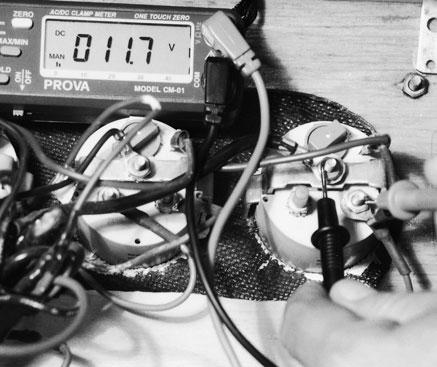
Fig. 10-5. Verifying voltage and good ground at the voltmeter. Fig. 10-6. Simplified wiring diagram for temperature, fuel, and oil-pressure gauges.
Fig. 10-7. Testing the temperature sending unit. With the wire to the sender removed, I’m grounding it out on the engine block with the ignition key in the “on” position; the needle on the temperature gauge on the dash panel should read at the maximum side of the gauge.
placed. If there is no change in the position of the needle, trace the power to the instrument and verify the continuity of the ground lead. Replace or repair these wires as needed.
If both of these leads are in good order and behaving as they should, the fault is in the instrument itself. Figure 10-7shows the wire disconnected at the sending unit and shorted to the engine block. This is what your dash-panel-mounted instrument should read if the fault is simply with the sending unit, which is the most common difficulty. This test is for a one-wire sending unit. If your unit has two wires attached to it, disconnect one of the wires from the sender and touch it to the terminal on the sender for the other wire. Watch the gauge with the ignition on, or get someone to watch the gauge needle for you. If the needle moves as you connect these leads, the problem is in the sending unit.
Fuel Gauges
Fuel gauges are wired exactly as temperature gauges but use a different type of variable resistor as the sending unit. The senders are located inside the fuel tank; you need access to the top of the tank to locate the senders and the wiring. To test the sender, turn the ignition key on, disconnect the wire from the sender, and ground it at either the black lead on the sender or directly to the tank. Observe the gauge.
LT
+12 GND
SEND
Instrument Common Ground
Engine or Tank Sending Unit
Ignition 12V

Senders on metal tanks often have only one wire, and the sender grounds to the tank itself. Disconnect the wire and ground it on the tank. In either case, if the needle moves so that the gauge reads full, the sender is bad and must be replaced.
In some instances fuel gauges work fine at some fuel levels and not at others. This erratic reading is a function of the sender design, and partial failure is not uncommon. To check, remove the screws holding the sender in place on the top of the tank and lift it out. Next, attach a jumper lead between the tank ground lead and the grounding connection on the sender. Again, with the ignition key on, move the float on the sender up and down while carefully observing the gauge on your instrument console. You may need an extra set of eyes to help you here, depending on the distance between the sender and the gauge. If the needle on the gauge acts erratically as you move the float assembly up and down, the float sender needs replacement.
Figure 10-8shows a sender removed and being tested. An important safety note here is to carefully inspect the condition of the gasket sealing the float mechanism to the tank. If any doubt exists as to its condition, replace the gasket. A fuel leak here is extremely dangerous and cause for immediate concern.
If your tests of the fuel-gauge sending unit cause no movement of the needle on the gauge, verify that you have power and good ground at the instrument, just as with the temperature gauge already described. If this fails to locate the problem, replace the gauge.
Oil-Pressure Gauges
Oil-pressure gauges are tested in the exact same way as both the temperature and fuel gauges mentioned already. Figure 10-9 on page 155shows the location of a typical oil-pressure sending unit on a General Motors “V” block used widely by MerCruiser, OMC, Volvo Penta, and other marine-engine manufacturers. For the exact location of the sending unit on your engine, refer to your engine workshop manual.

Fig. 10-8. Fuel tank sender removed and being tested. Move the float up and down while watching the ohmmeter. Look for a progressive change in resistance value. Any “OL” readings while performing this test indicate a “dead” spot in the sender, and it will need replacement.
Trim Gauges
As mentioned earlier, trim gauges, generally found only on outboard and IO boats, have an extremely high failure rate, because the sending units on these boats are located underwater on the engine drive unit.
These sending units are sealed and use two wires to connect the sender to the inside of the boat. The wires are fed through the drive unit’s gimbaled bracket assembly, disappearing behind the engine where they are extremely difficult to get at. Besides the difficulty of getting to the wires, the hole where the wires pass through the transom must be properly sealed to prevent seawater from leaking into the boat. Unless you’re an experienced technician, I do not recommend attempting to replace these senders on your own. This is a good job for a professional with experience not only in the replacement of trim-gauge sending units but their proper adjustment as well.
Finally, if you have any real doubt about the accuracy of your gauges, you should consult a professional with the mechanical and elec-


