10 minute read
Using Your Multimeter


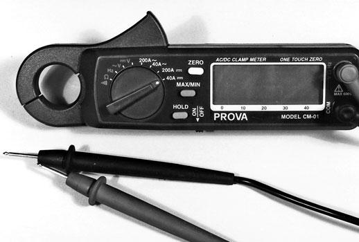
Fig. 3-2. Ancor/Prova clamp-type meter. This unit retails for around $300 and offers amperage reading capability up to 200 amps and a frequency-checking function, useful for some AC tests. Made by Prova, marketed in the United States by Ancor.
marine applications, such as those used in battery isolators. It does work for testing most alternators, but it may not be adequate for many inboard or inboard-outboard starter-current tests. The Ancor (part number 702070) is available through major marine retailers such as Defender Industries and West Marine for about $300.
Fluke Model 336
If you’re the type that simply has to have the best, Fluke Corporation makes what I consider to be some of the finest multimeters available anywhere. There are other fine meters, of course, but Fluke’s top-ofthe-line Model 336 offers one additional feature that will be useful if your boat is equipped with extensive AC circuitry such as a generator, inverter, or airconditioning and refrigeration systems. This meter will measure up to 600 amps DC and 600 amps AC, far beyond what most boaters need. It does not have a diode-test function, however, nor will it measure AC frequency.
Figure 3-3 shows a Fluke Model 336 true RMS clamp-type inductive meter. It’s available through all the major marine supply houses in the United States for about $275.
Both of these meters come with fairly easy-toread instructions, but be warned that the meter companies in general assume that you know how to attach the meters to the circuit correctly for the measurement you’re making. Reading the sections that follow will assure that you do!

Fig. 3-3. Fluke Model 336 clamp-type meter. This is a true RMS (root-mean-square) meter that can read up to 600 AC or DC amps. This is an excellent choice if you do a lot of AC work. Its shortcoming is that its ohms scale is not as sensitive as other meters I’ve used. This model sells for about $275.
There are literally hundreds of checks and tests that you’ll be able to carry out with your new multimeter. However, at least 90 percent of everything you’ll ever need to do will involve some form of the following four basic procedures: voltage measurement, voltage drop, amperage measurement, and resistance measurement. These procedures are so important that we discuss each in detail. Measuring voltage is the easiest, so let’s cover that one first.
Measuring Voltage
To test for voltage, first make sure that your meter is turned on and that the leads are inserted into the correct sockets (the leads that came with your new meter probably have spike-like probes on the ends,
Fig. 3-4. Meter on a volts scale hooked in parallel across a battery. A fully charged battery would read between 12.6 and 13.5 volts.

although a rare few might have alligator clips). The black lead goes into the socket that’s probably marked “COM,” and the red one goes into the socket marked “DCV” or something similar. If you do not have a self-scaling meter, also double-check to make sure that your meter is set to the proper range (20 volts for a 12-volt system). Now go to one of your boat’s 12-volt batteries and touch the black probe to the negative terminal and the red probe to the positive terminal. You should be able to read the battery voltage on your meter’s digital readout. If your battery has a full charge, this reading will be between 12.6 and 13.5 volts. A negative sign in front of the voltage means that you have the probes connected backwards.
That’s all there is to a voltage check. Once you have your meter set up properly, any time you touch the red probe to a hot positive terminal or bare wire and the black probe to a negative terminal or wire (or to ground), your meter will tell you the voltage at the point the red probe is touching. In other words, whenever your meter leads are connected to the circuit in parallel, as is explained in chapter 1, with some sort of load between them, you get a voltage reading.
Inexperienced meter users often make simple mistakes and become puzzled when their new meter shows no reading at all. This absence of a reading can be dangerous because it can lead the novice to believe the circuit is turned off when it’s in fact still live or hot.
Figure 3-5 on page 32 illustrates a multimeter properly connected to a 12-volt circuit to check for adequate voltage at a cabin light. The red meter lead is connected to the positive terminal on the light, and the black lead is connected to the negative connection.
Many beginners get confused when they try to check voltage at points throughout a circuit and can’t figure out what to do with the black lead. This lead should always be connected to the yellow (or black on older boats) lead of the circuit you’re testing or to a good ground connection.
Figure 3-6 on page 33 shows this same circuit with a meter hooked up in parallel to the switch activating the circuit. In effect, both meter leads are connected to a positive feed with no load between them. This hookup is incorrect and will not show a voltage reading under any circumstances.
Testing for Voltage Drop
Voltage drop, as we discovered in chapter 1, is the natural and unavoidable loss in voltage as amperage works to overcome resistance in a circuit. The drop is the amount of source voltage loss caused by the inherent resistance to electrical flow through the wiring in the circuit and any connections where wires and circuit components are installed.
Virtually all circuits contain some resistance. Thus, there is always some voltage drop in every circuit. This is true in AC circuits as well as in DC circuits. However, because of the trade-off between voltage and amperage (as voltage in a circuit goes up, the amperage required to do the same amount of work goes down), the drop in a 120-volt AC circuit is of little consequence. With low-voltage DC circuits, however, voltage drop is a major concern and you’ll need to know how to measure it.
So how much voltage drop is acceptable? Once again our friends at the ABYC offer some guidelines. Section E-11 of the Standards and Technical Information Reports talks about critical and noncritical circuits. Certain fixtures such as navigation lights, bilge pumps, and navigation equipment are required for safety, and their efficient operation is critical. However, the brightness of a cabin light or the speed of a fan in the galley just isn’t that important. Thus, the standards allow only a 3 percent maximum voltage drop for critical equipment and up to a maximum of 10 percent voltage drop for noncritical equipment. In a perfect world, and certainly in any electrical work you perform, it’s really best to shoot for 0 percent voltage drop as an ideal, but in the real world some voltage drop will always be present, especially in long wire runs.
There are several simple math problems that may help you to get a feel for what the ABYC maximum voltage drop figures mean.
Assume a 12-volt system. If a noncritical circuit is allowed a 10 percent maximum voltage drop, you need to know what 10 percent of the system voltage for your 12-volt circuit equals. In practice the actual numbers will be slightly different. A fully charged 12volt battery will have a voltage of between 12.6 and 13.5 volts. The actual voltage would change the following numbers slightly, but we will use the 12-volt figure to simplify the math.
To find the allowable voltage drop, turn the percentage into a decimal and multiply it by 12 (the system voltage in this example). The problem looks like this: 0.10 x 12 = 1.2. The maximum allowable voltage loss would be 1.2 volts, so by subtracting 1.2 volts from the original 12 volts, you end up with 10.8 volts as a minimum allowable voltage at any point in the circuit. Applying this same math to the 3 percent criteria, multiplying 0.03 x 12 gives a maximum allowable voltage drop of 0.36 volt, which means that 11.64 volts would be the minimum allowed at the appliance.
Circuit Protector Switch “On”
Battery Cabin Light Cabin Light Cabin Light
Fig. 3-5. Cabin light circuit diagram with a voltmeter connected to check voltage going to one of the light fixtures.
Measuring Voltage Drop: Method 1
So, now that you have an understanding of the voltage drop that’s allowed in critical and noncritical circuits, how can you actually measure it with your multimeter? There are two methods. The first method is probably the simplest to understand, but it won’t always give the best results when you’re trying to isolate the exact spot in the circuit that’s causing a problem.
Circuit Protector Switch “On”
Battery
Let’s assume you’re checking voltage drop at the light fixture in the head. First make sure that all DC circuits on board your boat except the one you’re checking are turned off. Battery voltage must be kept as stable as possible for this test, and any circuits that are turned on will drain the battery, if only slightly; this slight drain can alter your readings. Now check the voltage at your battery as described above. If you’re checking voltage at the distribution panel, connect your meter with the red lead attached to the positive bus at the back of the panel and the black lead attached to the negative bus. Record your reading to at least two decimal places. Fractions of a volt count here!
Next, go to the light socket and check the voltage. Again, the red test lead probe should be attached to the positive side of the fixture and the black probe to the negative side. You may have to disassemble the fixture to get access to the contacts for the light bulb. Put the red probe on one contact and the black to the other and take a direct reading. Make sure the
circuit is on and the bulb is lit. If you’re working with one of the more modern bayonet bulb holders, connect the red probe to the left-side bulb clamp and the black probe to the right side and take a direct reading. If the reading you get is the same as the reading at the battery or distribution panel, great! No voltage drop is present. If the reading is lower than the source voltage, as it usually is, there is a voltage drop present. To measure it, subtract your reading from thesource voltage. The difference between the two readings is the voltage drop between the power source and the appliance. Record the reading. To determine the percentage of drop, subtract the light-socket reading from the source-voltage reading and Cabin Light Cabin Light Cabin Light divide the result by the original source voltage. Shift your decimal point two places to the right, Fig. 3-6. Incorrect hookup of voltmeter across the switch of the same and you’ll have found the percentage of drop incabin light circuit. When the meter is connected in this manner, the that particular circuit. Depending upon whichsource voltage cannot be measured. The only reading you would get here is the voltage drop through the switch. category the circuit falls into, the drop must be less than 3 percent or less than 10 percent. If you get more than the 3 percent or 10 percent limit, the circuit has excessive voltage drop, which is probably caused by wiring that’s too small for the length of the circuit or a loose or corroded connection. You must now trace the exact fault. The next voltage-drop test will isolate the drop between the positive conductor and the negative conductor of the circuit. Figure 3-7 on page 34 shows voltage being checked at the back of a typical distribution panel. Figure 3-8 on page 34 shows the meter connections at your multimeter, and correct meter attachment at a variety of typical bulb holders.
Measuring Voltage Drop: Method 2
The second method for checking voltage drop is sometimes difficult for the beginner to understand. The meter will be connected in parallel, but you won’t attach your lead probes to separate positive or negative conductors. Instead, attach both your probes to the same conductor or between a terminal in the circuit and a terminal on the appliance you’re


