Powerboater's Guide to Electrical Systems - PDF DOWNLOAD

Page 181

Alternating Current and AC Equipment To test a GFCI, simply depress the test button on the assembly faceplate. This trips the internal breaker and actually exercises the outlet’s inner workings to ensure that it’s functioning as it should. If the test and reset buttons feel spongy and seem to have lost their crisp snap action, odds are good that the GFCI mechanism is corroded, and the outlet should be replaced. Another point worth mentioning here is that just because the dock box that your boat is connected to at the marina is protected by GFCI (and it always should be), you shouldn’t think that you’re protected from shock hazard on your boat. These dockside GFCIs are likely to be forgotten by the maintenance crew and never tested until it’s too late. To be safe, always test the dockside outlets before you plug in your shore-power cord, and to eliminate any worry, upgrade your boat with this important protection as soon as you can.

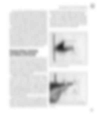
these problems usually originate at the dock, not on the boat, and it’s easy to check for them yourself. Figure 11-10 demonstrates using the inductive AC tester to see if there is voltage present at an outlet. If the tester’s LED flashes and it emits a steady beeping noise, AC is present in the circuit. The only remaining question is how much voltage. To determine that, you’ll need your multimeter.

Checking Voltage, Continuity, and Polarity on AC Circuits Sooner or later, problems will crop up with the AC circuits on your boat, and you’ll need to do basic multimeter tests for voltage, polarity, and continuity. There is no need to be afraid of doing these tests on AC circuits, even for the novice, but following some basic rules, in addition to the safety rules listed above, will ensure that you won’t damage your meter or end up having a shocking experience. Besides your multimeter, several small, inexpensive testers can be extremely useful when working around AC systems. Figure 11-9 shows an LED outlet tester with a built-in GFCI test function, and figure 11-10 shows an inductive voltage sensor used for verifying the presence of AC voltage, even behind panels and through insulation. The LED outlet tester is useful in determining whether reverse polarity exists and whether or not there is an open circuit in any of the three conductors. It is not at all uncommon for low voltage to be a problem in an AC circuit, or reverse polarity for that matter. A disconnected green grounding conductor is quite common and can go unnoticed until someone gets a shocking jolt. The good news here is that

Fig. 11-9. An LED outlet tester.

Fig. 11-10. Using the inductive AC tester to check voltage at an outlet.

167


Turn static files into dynamic content formats.

Create a flipbook

Articles inside

Index

18min
pages 215-223

Resources

1min
page 214

Glossary

14min
pages 207-213

Installing Your Own Radar

5min
pages 205-206

Installing a GPS Receiver

2min
page 204

Power Supply

3min
page 196

Galvanic Isolators

6min
pages 191-193

AC Generators

5min
pages 189-190

Comparisons between AC and DC Circuits

6min
pages 173-175

AC Overcurrent Protection

4min
pages 176-177

Selecting a DC-to-AC Inverter

17min
pages 184-188

Color Coding for AC Wiring

3min
page 172

Checking Voltage, Continuity, and Polarity on AC Circuits

7min
pages 181-183

Ground-Fault Circuit Interrupters

2min
page 180

The Future

1min
page 169

General Instrument Troubleshooting

16min
pages 163-168

Abnormal Instrument Readings

3min
page 162

Adding a New Compact-Disc Player

7min
pages 158-160

Installing a New Bilge Pump

10min
pages 154-157

Installing a New Cabin Light

3min
page 153

Other Outboard-Engine Starter-Motor Problems

1min
page 149

Testing the Neutral-Safety Switch

3min
page 146

Engine Ignition Switch

4min
pages 147-148

Outboard-Engine Starter Circuits

10min
pages 142-145

Troubleshooting Starter-Motor Circuits

6min
pages 139-141

Starter-Motor Problems and Solutions

2min
page 138

Testing Your Stop Switch

3min
page 133

Final Checks and Ignition Timing

8min
pages 134-136

Outboard and PWC Ignition Tests

19min
pages 126-132

Beyond the Basics: Outboard and PWC Ignition Systems

6min
pages 124-125

Shore-Power Battery Charging Systems and Installations

9min
pages 110-112

MerCruiser Thunderbolt IV and Thunderbolt V Systems

7min
pages 121-123

Solar Cells

2min
page 113

Outboard-Engine Charging Systems

5min
pages 108-109

Battery Installations

15min
pages 90-95

Battery Maintenance and Testing

4min
pages 88-89

Which Battery Is Right for You?

9min
pages 83-85

Battery Safety

5min
pages 86-87

Connecting the Dots: Making Wiring and Connection Repairs

8min
pages 73-78

Testing Your Batteries

10min
pages 96-99

Types of Lead-Acid Batteries

9min
pages 80-82

Wire Routing and Support

4min
pages 71-72

Acceptable Locations for Fuses and Circuit Breakers

4min
pages 69-70

Levels of Circuit Protection

1min
page 68

Testing Fuses and Circuit Breakers

2min
page 67

Ignition Protection

1min
page 66

Fuses and Circuit Breakers

14min
pages 60-65

Wire Size

2min
page 56

Wire Insulation

2min
pages 57-59

Basic Wiring

3min
page 55

Drawing Your Own Wiring Diagram

9min
pages 36-38

Expanding the Basic Circuit

3min
page 33

Wire Identification and the ABYC Color Code

8min
pages 29-32

Using Your Multimeter

10min
pages 44-47

Voltage Drop

2min
page 22

Ohm’s Law and What It Can Tell Us

8min
pages 19-21

Tools

2min
pages 24-25

Measuring Amperage

4min
pages 48-50
Issuu converts static files into: digital portfolios, online yearbooks, online catalogs, digital photo albums and more. Sign up and create your flipbook.
Powerboater's Guide to Electrical Systems - PDF DOWNLOAD by www.heydownloads.com - Issuu