6 minute read
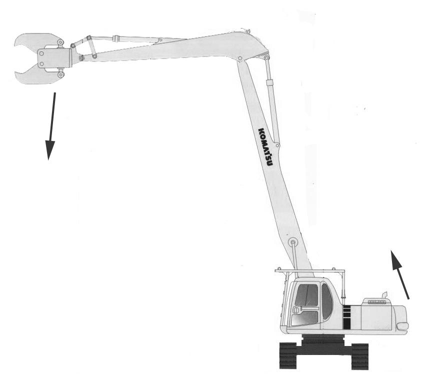
MACHINES READY FOR ATTACHMENTS

from Komatsu PC210, PC210LC-6K PC240LC,PC240NLC-6K Hydraulic Excavator Operation & Maintenance Manual

EXPLANATION OF COMPONENTS
2
Advertisement
1. STOP VALVE
This valve stops the flow of the hydraulic oi
2 1
l(1) FLOW : Hydraulic oil flows
(2) STOP : Hydraulic oil stops. Set this valve to the STOP position when removing or installing attachments.
AM092000A
2. SELECTOR VALVE
This switches the flow of the hydraulic oil.
For details of the attachment to install and the direction of right 3-way valve, see “5. HYDRAULIC CIRCUIT” on page 257.
3. CONTROL PEDAL FOR ATTACHMENT
This is used to operate the attachment.
The pedal can be depressed to the front, neutral, and rear to operate the attachment as follows.
Hydraulic breaker
Pedal front (1) actuated
Pedal neutral (N) stopped
Pedal rear (2) stopped
When the breaker is used, select the breaker operation mode (B.O) in the monitor panel.
For other attachments, confirm with the manufacturer regarding the relation between pedal operation and attachment movement when the attachment is mounted. Use the attachment only after confirming the above.
Flow from the left hand second attachment pedal can be modified by adjusting the stroke limiting bolts (1) located under the pedal.
4. ACCUMULATOR
WARNING The accumulator is filled with high-pressure nitrogen gas, and it is extremely dangerous if it is handled in the wrong way.
For handling procedure, see "HANDLING ACCUMULATOR".
The accumulator is provided to release the pressure remaining in the attachment circuit after stopping the engine. Normally, never touch it.
2 1
N
1
AM092130D
1
PC21056
AM090140A
5. HYDRAULIC CIRCUIT
Change-over hydraulic circuit
Contact dealer to set left hand boom piping relief pressure.

When using the breaker and the general attachment (Crusher etc.), turn the rotor of the 3 way valve a to change over according to the following illustration.
(The marks indicating the port direction are stamped on the 3-way valve).
Attachments Right 3-way valve (1)
Front
1-way frow (Breaker)
Front 2-Way flow (Crusher)
NOTICE Perform work only after the engine is stopped and the work equipment and machine body are in a stable posture on the ground.
CONNECTING HYDRAULIC CIRCUIT
When connecting the attachment, connect the circuit as follows.
1. Remove blind plugs (1) located on the end of the stop valve piping (2 places, left and right).
Take care not to lose or damage the removed parts.
2. Connect attachment tubes (2) supplied by the attachment manufacturer to the end from which the plug was removed in step (1).
Path of Oil
The direction of operation of the pedal and the path of the oil are as shown in the diagram below.
AM092080A
ATTACHMENT MOUNTING/DISMOUNTING PROCEDURE
Dismounting procedure
1. Curl the arm in then lower the boom to the ground. Set the attachment valves on the arm to the stop position as shown.
2. Place the attachment on the ground and stop the engine.
3. Operate levers and attachment pedals to full stroke 2 to 3 times to release hydraulic system pressure. Ensure oil temperature is low.
4. Remove the hoses on the attachment side. Install the blind plugs to the two outlets (1).
Install blind plugs to the attachment hoses to prevent entry of dirt during dismounting and storage.
5. Dismount the attachment by removing the retaining pins (2 pins). Then, mount the bucket.
For the bucket mounting procedure, see “REPLACEMENT AND INVERSION OF BUCKET” on page 131.
6. After the bucket is mounted, check the hydraulic oil level.
fMOUNTING PROCEDURE
1. Remove the bucket.
For bucket dismounting procedure, see “REPLACEMENT AND INVERSION OF BUCKET” on page 133.
2. Place the attachment on a flat place, install pins (A) and (B) to the arm in that order.
3. After mounting the attachment, stop the engine. Operate each work equipment control lever and the attachment control pedal to full stroke back and forth, right and left to eliminate the internal pressure in the hydraulic circuit.
4. After confirming low oil temperature, remove the blind plug from the outlet and inlet port respectively.
Take care that no dust, mud, etc. adheres to the hose mouthpiece portions. If O-ring is damaged, replace it with a new one. FLOW STOP
5. Turn the rotor of the stop valve connected to the inlet and outlet piping on the arm side face to the free position.
6. Confirm that oil level in the hydraulic oil tank is correct, after mounting the attachment.
OPERATION
WARNING
Be careful when operating the pedal in the deceleration range. The engine speed will rise suddenly.
Do not put your foot on the pedal except when operating the pedal. If rest your foot on the pedal during operations, and it is depressed by accident, the attachment may move suddenly and cause serious damage or injury.
Operate the attachment as follows.
WHEN USING BREAKER
Set the stop valve to the FLOW position, and depress the front of the pedal to operate the breaker.
Select the working mode for breaker (B.O).
Precautions when using
Check that the stop valve is in the FLOW position.
Check that the selector valve is in the position for using the breaker.
For details of the path followed by the oil, see “5. HYDRAULIC CIRCUIT” on page 257.
For details of other precautions when handling the breaker, read and use correctly the instruction manual provided by the breaker manufacturer.
When using the breaker, the hydraulic oil deteriorates more rapidly than for normal operations, so change the hydraulic oil and replace the element at a shorter interval.
For details, see “MAINTENANCE WHEN USING HYDRAULIC BREAKER” on page 212.
FLOW STOP
N
AM092130D
When using general attachment such as crusher
When the pedal is depressed at the front to rear portitions, the attachment is actuated.
Precautions when using
N
Check that the stop valve is at the flow position.
Confirm that the selector valve is set tot the position for general attachments such ast the crusher.
For details of the oil path, see “5. HYDRAULIC CIRCUIT” on page 257.
For other precautions when using the attachment, see the instruction manual provided by the attachment manufacturer.
LONG TERM STORAGE
If the machine is not to be used for a long period, do as follows.
Set the stop valve to the STOP position.
Install the blind plugs and O-rings to the valves.
If the pedal is operated when there is no breaker or general attachment installed, it will cause overheating and other problems.
SPECIFICATIONS
Attachments Right 3-way valve (1)
Front
1-way frow (Breaker)
Front 2-Way flow (Crusher)
AM092130D
FLOW STOP
Hydraulic specifications
Max. flow when flow is joined: 191 x 2 liter/min
Safety valve relief set pressure of service valve: 27500 kPa (280 kg/cm²)
Safety valve cracking set pressure of service valve: 24500 kPa (250 kg/cm²)
Left hand boom piping flow and right hand flow can have different pressures. Consult your dealer for various pressures available.
FIRST ATTACHMENT WITH CLAM-SHELL OPTION
Machines fitted with a single attachment circuit can also be supplied with clam-shell grab piping or can have such piping fitted at a later time.
The clam-shell open/close function uses the bucket cylinder circuit with the bucket cylinder disable by the two arm mounted stop valves (Left hand side example shown below).
The first attachment circuit (right hand cab pedal) can be used to rotate grabs with a rotary function with the revo-frame mounted 3- way valve set to 2-way flow.
Fine control of rotation can be achieved by adjusting the maximum output of the first attachment using the righthand panel mounted 10 position switch.
Normal flow to bucket cylinder Flow to clam shell
FIRST AND SECOND ATTACHMENT
This option can only be fitted to machines that have the main valve converted to or supplied with 2 attachment spool additions (8 spools in total)
The arm end valves are set to the flow or stop position as shown in the figure below.
The second attachment when fitted, is permanently set in two way flow with full flow (2-pump) output and full system pressure.
Attachment pressures can be modified by your local dealer on request and can have different pressures for left hand and righthand piping by modifying the relief valves in the main control valve portions.
When handling attachments please follow the same procedure and precautions as applied to the first attachment circuit (attachment mounting/dismounting).
FLOW
STOP