17 minute read
Chapter 4 Troubleshooting


Troubleshooting
Use the following procedure as a guide for computer problems. NOTE: The diagnostic tests are intended to test only Acer products. Non-Acer products, prototype cards, or modified options can give false errors and invalid system responses. 1. Obtain the failing symptoms in as much detail as possible. 2. Verify the symptoms by attempting to re-create the failure by running the diagnostic test or by repeating the same operation. 3. Use the following table with the verified symptom to determine which page to go to.
Symptoms (Verified) Power failure. (The power indicator does not go on or stay on.) POST does not complete. No beep or error codes are indicated.
POST detects an error and displayed messages on screen. Other symptoms (i.e. LCD display problems or others). Symptoms cannot be re-created (intermittent problems). Go To “Power System Check” on page 70.
“Power-On Self-Test (POST) Error Message” on page 73 “Undetermined Problems” on page 82 “Error Message List” on page 74
“Power-On Self-Test (POST) Error Message” on page 73 Use the customer-reported symptoms and go to “Power-On Self-Test (POST) Error Message” on page 73 “Intermittent Problems” on page 81 “Undetermined Problems” on page 82
External Diskette Drive Check
Do the following to isolate the problem to a controller, driver, or diskette. A write-enabled, diagnostic diskette is required. NOTE: Make sure that the diskette does not have more than one label attached to it. Multiple labels can cause damage to the drive or cause the drive to fail. Do the following to select the test device. 1. Boot from the diagnostics diskette and start the diagnostics program. 2. See if FDD Test is passed as the program runs to FDD Test. 3. Follow the instructions in the message window. If an error occurs with the internal diskette drive, reconnect the diskette connector on the system board. If the error still remains: 1. Reconnect the external diskette drive/DVD-ROM module. 2. Replace the external diskette drive/CD-ROM module. 3. Replace the main board.
External CD-ROM Drive Check
Do the following to isolate the problem to a controller, drive, or CD-ROM. Make sure that the CD-ROM does not have any label attached to it. The label can cause damage to the drive or can cause the drive to fail. Do the following to select the test device: 1. Boot from the diagnostics diskette and start the diagnostics program. 2. See if CD-ROM Test is passed when the program runs to CD-ROM Test. 3. Follow the instructions in the message window. If an error occurs, reconnect the connector on the System board. If the error still remains: 1. Reconnect the external diskette drive/CD-ROM module. 2. Replace the external diskette drive/CD-ROM module. 3. Replace the main board.
Keyboard or Auxiliary Input Device Check
Remove the external keyboard if the internal keyboard is to be tested. If the internal keyboard does not work or an unexpected character appears, make sure that the flexible cable extending from the keyboard is correctly seated in the connector on the system board. If the keyboard cable connection is correct, run the Keyboard Test. If the tests detect a keyboard problem, do the following one at a time to correct the problem. Do not replace a non-defective FRU: 1. Reconnect the keyboard cables. 2. Replace the keyboard. 3. Replace the main board.
The following auxiliary input devices are supported by this computer: Numeric keypad External keyboard
Memory check
Memory errors might stop system operations, show error messages on the screen, or hang the system. 1. Boot from the diagnostics diskette and start the doagmpstotics program (please refer to main board. 2. Go to the diagnostic memory in the test items. 3. Press F2 in the test items. 4. Follow the instructions in the message window. NOTE: Make sure that the DIMM is fully installed into the connector. A loose connection can cause an error.
Power System Check
To verify the symptom of the problem, power on the computer using each of the following power sources: 1. Remove the battery pack. 2. Connect the power adapter and check that power is supplied. 3. Disconnect the power adapter and install the charged battery pack; then check that power is supplied by the battery pack. If you suspect a power problem, see the appropriate power supply check in the following list: “Check the Power Adapter” on page 71 “Check the Battery Pack” on page 72
Unplug the power adapter cable from the computer and measure the output voltage at the plug of the power adapter cable. See the following figure
1. If the voltage is not correct, replace the power adapter. 2. If the voltage is within the range, do the following: Replace the System board. If the problem is not corrected, see “Undetermined Problems” on page 82. If the voltage is not correct, go to the next step. NOTE: An audible noise from the power adapter does not always indicate a defect. 3. If the power-on indicator does not light up, check the power cord of the power adapter for correct continuity and installation. 4. If the operational charge does not work, see “Check the Battery Pack” on page 72.
Pin 1: +19 to +20.5V Pin 2: 0V, Ground
To check the battery pack, do the following: From Software: 1. Check out the Power Management in control Panel 2. In Power Meter, confirm that if the parameters shown in the screen for Current Power Source and Total
Battery Power Remaining are correct. 3. Repeat the steps 1 and 2, for both battery and adapter. 4. This helps you identify first the problem is on recharging or discharging. From Hardware: 1. Power off the computer. 2. Remove the battery pack and measure the voltage between battery terminals 1(+) and 6(ground). See the following figure
3. If the voltage is still less than 7.5 Vdc after recharging, replace the battery. To check the battery charge operation, use a discharged battery pack or a battery pack that has less than 50% of the total power remaining when installed in the computer. If the battery status indicator does not light up, remove the battery pack and let it return to room temperature. Re-install the battery pack. If the charge indicator still does not light up, replace the battery pack. If the charge indicator still does not light up, replace the DC/DC charger board.
Touchpad Check
If the touchpad doesn’t work, do the following actions one at a time to correct the problem. Do not replace a non-defective FRU: 1. Reconnect the touchpad cables. 2. Replace the touchpad. 3. Replace the system board. After you use the touchpad, the pointer drifts on the screen for a short time. This self-acting pointer movement can occur when a slight, steady pressure is applied to the touchpad pointer. This symptom is not a hardware problem. No service actions are necessary if the pointer movement stops in a short period of time.
The POST error message index lists the error message and their possible causes. The most likely cause is listed first. NOTE: Perform the FRU replacement or actions in the sequence shown in FRU/Action column, if the FRU replacement does not solve the problem, put the original part back in the computer. Do not replace a non-defective FRU.
This index can also help you determine the next possible FRU to be replaced when servicing a computer. If the symptom is not listed, see “Undetermined Problems” on page 82. The following lists the error messages that the BIOS displays on the screen and the error symptoms classified by function. NOTE: Most of the error messages occur during POST. Some of them display information about a hardware device, e.g., the amount of memory installed. Others may indicate a problem with a device, such as the way it has been configured. NOTE: If the system fails after you make changes in the BIOS Setup Utility menus, reset the computer, enter Setup and install Setup defaults or correct the error.
Error Code List
Error Codes Error Messages 006 Equipment Configuration Error Causes: 1. CPU BIOS Update Code Mismatch 2. IDE Primary Channel Master Drive Error (THe causes will be shown before “Equipment Configuration Error”) 010 Memory Error at xxxx:xxxx:xxxxh (R:xxxxh, W:xxxxh) 070 Real Time Clock Error 071 CMOS Battery Bad 072 CMOS Checksum Error 110 System disabled. Incorrect password is specified. <No error code> Battery critical LOW In this situation BIOS will issue 4 short beeps then shut down system, no message will show. <No error code> Thermal critical High In this situation BIOS will shut down system, not show message.
Error Message List
Error Messages FRU/Action in Sequence Failure Fixed Disk Reconnect hard disk drive connector. “Load Default Settings” in BIOS Setup Utility. Hard disk drive System board Stuck Key see “Keyboard or Auxiliary Input Device Check” on page 69. Keyboard error see “Keyboard or Auxiliary Input Device Check” on page 69. Keyboard Controller Failed see “Keyboard or Auxiliary Input Device Check” on page 69. Keyboard locked - Unlock key switch Unlock external keyboard Monitor type does not match CMOS - Run Setup Run “Load Default Settings” in BIOS Setup Utility. Shadow RAM Failed at offset: nnnn BIOS ROM System board System RAM Failed at offset: nnnn DIMM System board Extended RAM Failed at offset: nnnn DIMM System board System battery is dead - Replace and run Setup Replace RTC battery and Run BIOS Setup Utility to reconfigure system time, then reboot system.
System CMOS checksum bad - Default configuration used
RTC battery Run BIOS Setup Utility to reconfigure system time, then reboot system. System timer error RTC battery Run BIOS Setup Utility to reconfigure system time, then reboot system. System board
Error Messages FRU/Action in Sequence
Real time clock error RTC battery Run BIOS Setup Utility to reconfigure system time, then reboot system. System board
Previous boot incomplete - Default configuration used Run “Load Default Settings” in BIOS Setup Utility. RTC battery System board
Memory size found by POST differed from CMOS
Run “Load Default Settings” in BIOS Setup Utility. DIMM System board Diskette drive A error Check the drive is defined with the proper diskette type in BIOS Setup Utility See “External Diskette Drive Check” on page 69. Incorrect Drive A type - run SETUP Check the drive is defined with the proper diskette type in BIOS Setup Utility System cache error - Cache disabled System board CPU ID: System board DMA Test Failed DIMM System board Software NMI Failed DIMM System board Fail-Safe Timer NMI Failed DIMM System board Device Address Conflict Run “Load Default Settings” in BIOS Setup Utility. RTC battery System board Allocation Error for device Run “Load Default Settings” in BIOS Setup Utility. RTC battery System board Failing Bits: nnnn DIMM BIOS ROM System board Fixed Disk n None Invalid System Configuration Data BIOS ROM System board I/O device IRQ conflict Run “Load Default Settings” in BIOS Setup Utility. RTC battery System board Operating system not found Enter Setup and see if fixed disk and drive A: are properly identified. Diskette drive Hard disk drive System board
Error Message List
No beep Error Messages No beep, power-on indicator turns off and LCD is blank.
No beep, power-on indicator turns on and LCD is blank.
No beep, power-on indicator turns on and LCD is blank. But you can see POST on an external CRT. FRU/Action in Sequence Power source (battery pack and power adapter). See “Power System Check” on page 70. Ensure every connector is connected tightly and correctly. Reconnect the DIMM. LED board. System board. Power source (battery pack and power adapter). See “Power System Check” on page 70. Reconnect the LCD connector Hard disk drive LCD inverter ID LCD cable LCD Inverter LCD System board Reconnect the LCD connectors. LCD inverter ID LCD cable LCD inverter LCD System board
No beep, power-on indicator turns on and a blinking cursor shown on LCD during POST.
Ensure every connector is connected tightly and correctly. System board No beep during POST but system runs correctly. Speaker System board
Code Beeps
For Boot Block in Flash ROM E0h Initialize the chipset E1h Initialize the bridge E2h Initialize the CPU E3h Initialize the system timer E4h Initialize system I/O E5h Check force recovery boot E6h Checksum BIOS ROM E7h Go to BIOS E8h Set Huge Segment E9h Initialize Multi Processor EAh Initialize OEM special code EBh Initialize PIC and DMA ECh Initialize Memory type EDh Initialize Memory size EEh Shadow Boot Block EFh System memory test F0h Initialize interrupt vectors F1h Initialize Run Time Clock F2h Initialize video F3h Initialize System Management Mode F4h 1 Output one beep before boot F5h Boot to Mini DOS F6h Clear Huge Segment F7h Boot to Full DOS
LCD-Related Symptoms
Symptom / Error LCD backlight doesn't work LCD is too dark LCD brightness cannot be adjusted LCD contrast cannot be adjusted
Unreadable LCD screen Missing pels in characters Abnormal screen Wrong color displayed
LCD has extra horizontal or vertical lines displayed. Action in Sequence Enter BIOS Utility to execute “Load Setup Default Settings”, then reboot system. Reconnect the LCD connectors. Keyboard (if contrast and brightness function key doesn't work). LCD inverter ID LCD cable LCD inverter LCD System board Reconnect the LCD connector LCD inverter ID LCD cable LCD inverter LCD System board LCD inverter ID LCD inverter LCD cable LCD System board
Indicator-Related Symptoms
Symptom / Error Indicator incorrectly remains off or on, but system runs correctly Reconnect the inverter board Inverter board System board Action in Sequence
Power-Related Symptoms
Symptom / Error Action in Sequence Power shuts down during operation Power source (battery pack and power adapter). See “Power System Check” on page 70. Battery pack Power adapter Hard drive & battery connection board System board The system doesn’t power-on. Power source (battery pack and power adapter). See “Power System Check” on page 70. Battery pack Power adapter Hard drive & battery connection board System board The system doesn’t power-off. Power source (battery pack and power adapter). See “Power System Check” on page 70. Hold and press the power switch for more than 4 seconds. System board
Symptom / Error
Action in Sequence Battery can’t be charged See “Check the Battery Pack” on page 72. Battery pack System board
PCMCIA-Related Symptoms
Symptom / Error Action in Sequence
System cannot detect the PC Card (PCMCIA) PCMCIA slot assembly System board PCMCIA slot pin is damaged. PCMCIA slot assembly
Memory-Related Symptoms
Symptom / Error Memory count (size) appears different from actual size. Enter BIOS Setup Utility to execute “Load Default Settings, then reboot system. DIMM System board Action in Sequence
Speaker-Related Symptoms
Symptom / Error In Windows, multimedia programs, no sound comes from the computer.
Audio driver Speaker System board Internal speakers make noise or emit no sound. Speaker System board Action in Sequence
Power Management-Related Symptoms
Symptom / Error Action in Sequence The system will not enter hibernation Keyboard (if control is from the keyboard) Hard disk drive System board
The system doesn't enter hibernation mode and four short beeps every minute. See “Hibernation Mode” on page 34. Press Fn+oand see if the computer enters hibernation mode. Touchpad Keyboard Hard disk connection board Hard disk drive System board
The system doesn’t enter standby mode after closing the LCD
The system doesn't resume from hibernation mode.
The system doesn't resume from standby mode after opening the LCD. See “Hibernation Mode” on page 34. LCD cover switch System board See “Hibernation Mode” on page 34. Hard disk connection board Hard disk drive System board See “Hibernation Mode” on page 34. LCD cover switch System board
Symptom / Error Action in Sequence
Battery fuel gauge in Windows doesn’t go higher than 90%.
Remove battery pack and let it cool for 2 hours. Refresh battery (continue use battery until power off, then charge battery). Battery pack System board System hangs intermittently. Reconnect hard disk/CD-ROM drives. Hard disk connection board System board
Peripheral-Related Symptoms
Symptom / Error Action in Sequence
System configuration does not match the installed devices.
Enter BIOS Setup Utility to execute “Load Default Settings”, then reboot system. Reconnect hard disk/CD-ROM/diskette drives. External display does not work correctly. Press Fn+F5, LCD/CRT/Both display switching System board USB does not work correctly System board Print problems. Ensure the “Parallel Port” in the “Onboard Devices Configuration” of BIOS Setup Utility is set to Enabled. Onboard Devices Configuration Run printer self-test. Printer driver Printer cable Printer System Board Serial or parallel port device problems. Ensure the “Serial Port” in the Devices Configuration” of BIOS Setup Utility is set to Enabled. Device driver Device cable Device System board
Keyboard/Touchpad-Related Symptoms
Symptom / Error Action in Sequence Keyboard (one or more keys) does not work. Reconnect the keyboard cable. Keyboard System board Touchpad does not work. Reconnect touchpad cable. Touchpad board System board
Modem-Related Symptoms
Symptom / Error Internal modem does not work correctly. Modem phone port modem combo board System board Action in Sequence
NOTE: If you cannot find a symptom or an error in this list and the problem remains, see “Undetermined Problems” on page 82.
Intermittent system hang problems can be caused by a variety of reasons that have nothing to do with a hardware defect, such as: cosmic radiation, electrostatic discharge, or software errors. FRU replacement should be considered only when a recurring problem exists. When analyzing an intermittent problem, do the following: 1. Run the advanced diagnostic test for the system board in loop mode at least 10 times. 2. If no error is detected, do not replace any FRU. 3. If any error is detected, replace the FRU. Rerun the test to verify that there are no more errors.
The diagnostic problems does not identify which adapter or device failed, which installed devices are incorrect, whether a short circuit is suspected, or whether the system is inoperative. Follow these procedures to isolate the failing FRU (do not isolate non-defective FRU). NOTE: Verify that all attached devices are supported by the computer. NOTE: Verify that the power supply being used at the time of the failure is operating correctly. (See “Power System Check” on page 70): 1. Power-off the computer. 2. Visually check them for damage. If any problems are found, replace the FRU. 3. Remove or disconnect all of the following devices: Non-Acer devices Printer, mouse, and other external devices Battery pack Hard disk drive DIMM CD-ROM/Diskette drive Module PC Cards 4. Power-on the computer. 5. Determine if the problem has changed. 6. If the problem does not recur, reconnect the removed devices one at a time until you find the failing FRU. 7. If the problem remains, replace the following FRU one at a time. Do not replace a non-defective FRU: System board LCD assembly
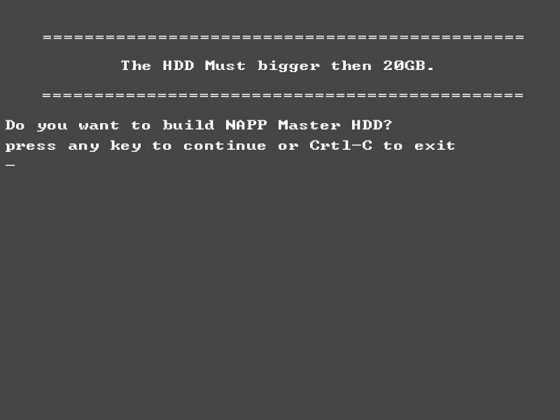
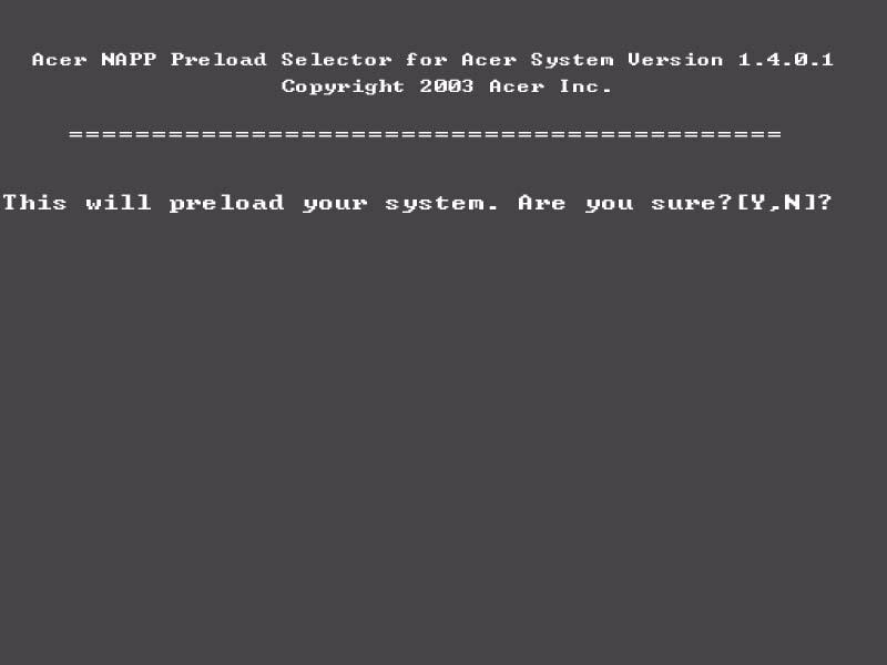
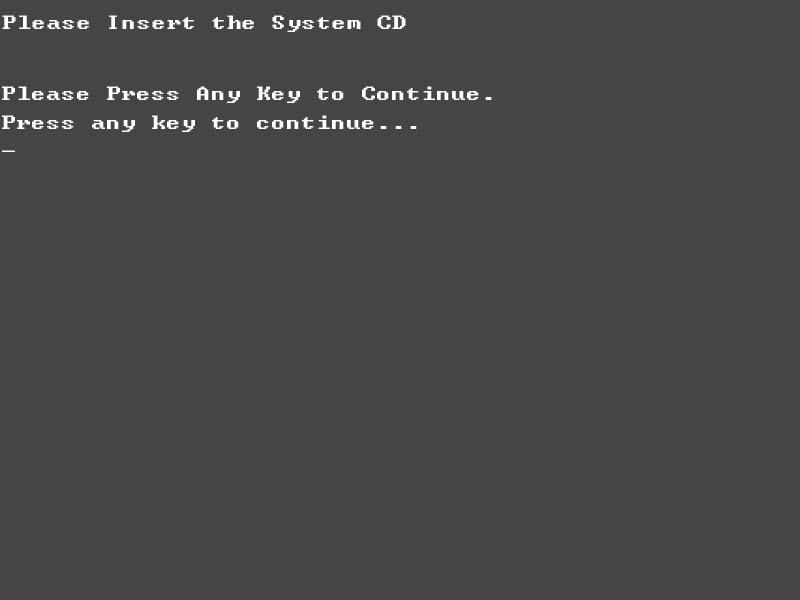
CD to Disk Recovery
5. Select CD to Disk Revocery.

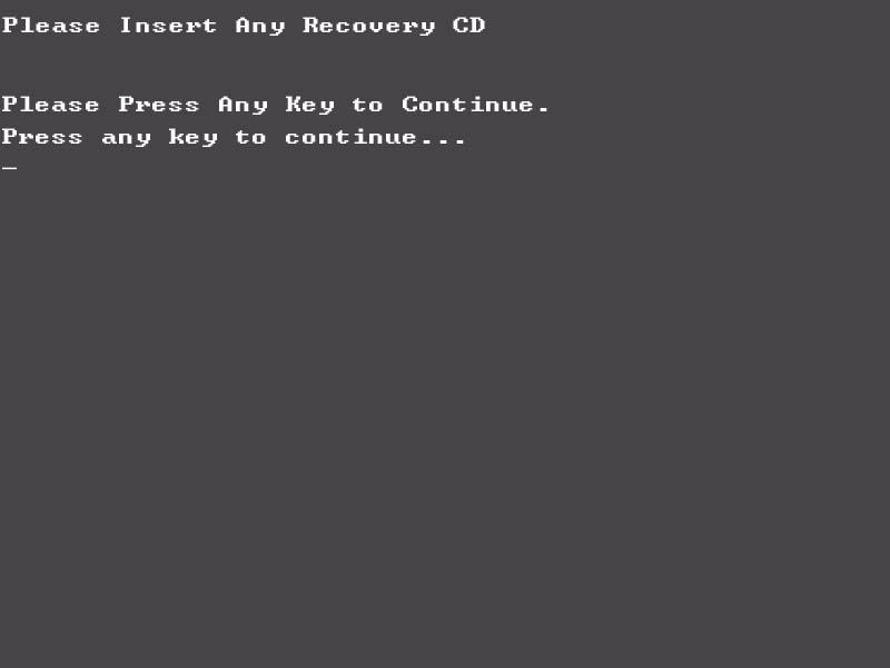
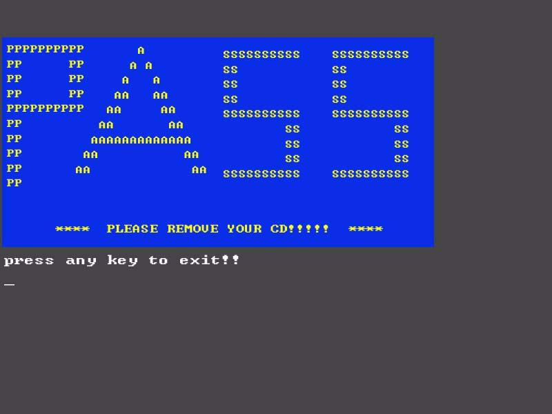
After you place the Recovery CD to the optical drive, you will see the display below.
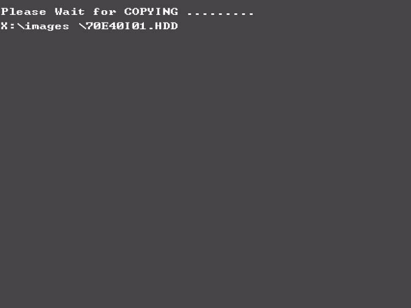
8. You will see the screen displaying “PASS” when the system has buit NAPP Master hard disc drive.
Disk to Disk Recovery
5. Select Disk to Disk Recovery. Then choose Single Language or Multi-Languages Recovery. NOTE: For Multi-Languages Recovery, not more than five languages could be loaded to the system.
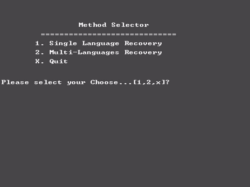
After you place the Recovery CD to the optical drive, you will see the display below.
8. You will see the screen displaying “PASS” when the system has buit NAPP Master hard disc drive.