5 minute read
Engine


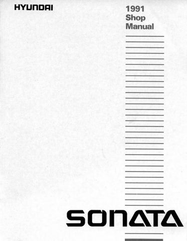
4. Lightly coat the O-ring (1) of the new oil filter with engine oil, and install the filter by completely turning it by hand.
VALVE CLEARANCE (Check and adjust as required)
Y10ECOA
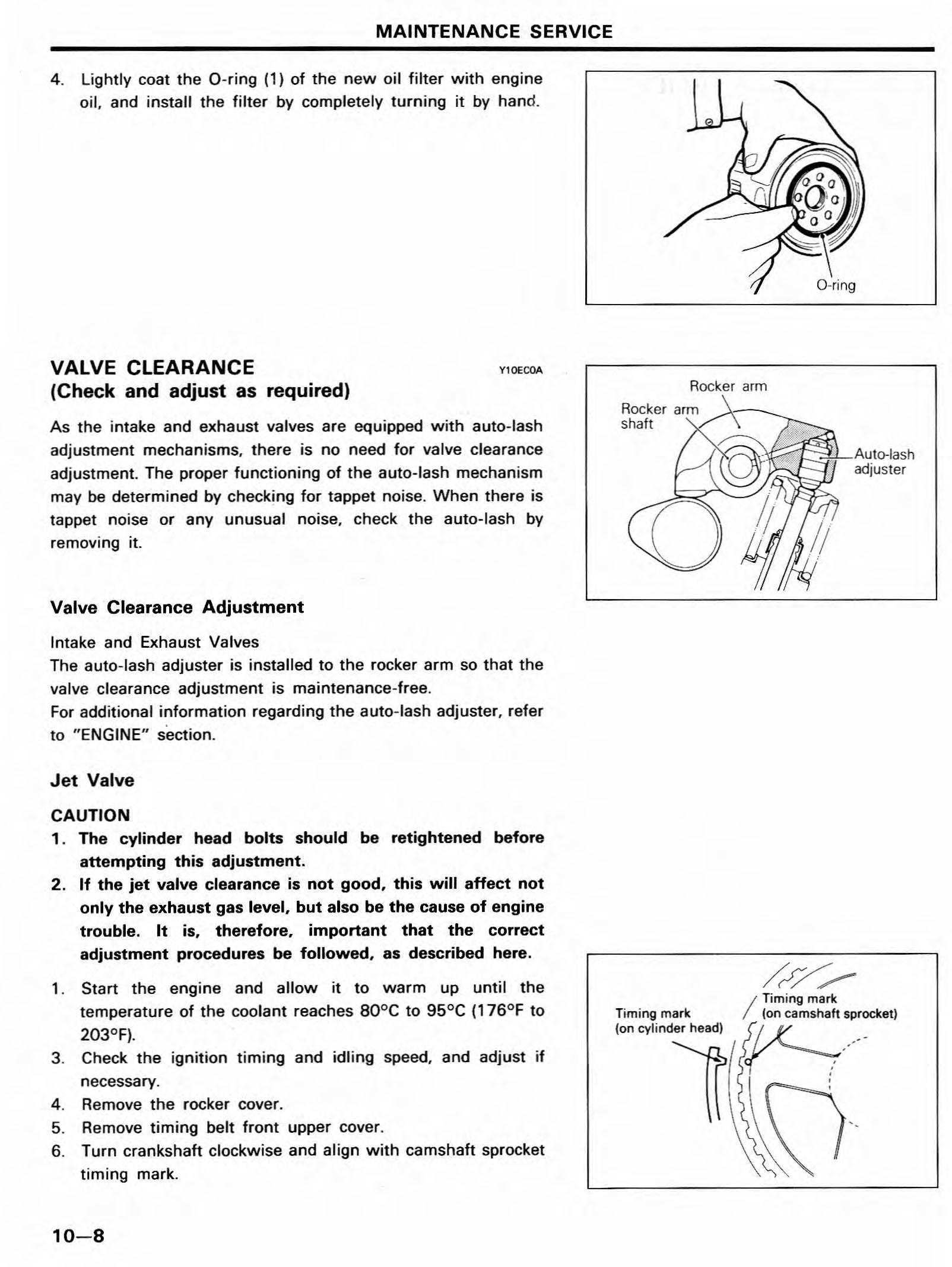
As the intake and exhaust valves are equipped with auto-lash adjustment mechanisms, there is no need for valve clearance adjustment. The proper functioning of the auto-lash mechanism may be determined by checking for tappet noise. When there is tappet noise or any unusual noise, check the auto-lash by removing it.
Valve Clearance Adjustment
Intake and Exhaust Valves The auto-lash adjuster is installed to the rocker arm so that the valve clearance adjustment is maintenance-free. For additional information regarding the auto-lash adjuster, refer to "ENGINE" section.
Jet Valve
CAUTION 1. The cylinder head bolts should be retightened before attempting this adjustment. 2. If the jet valve clearance is not good, this will affect not only the exhaust gas level, but also be the cause of engine trouble. It is, therefore, important that the correct adjustment procedures be followed, as described here.
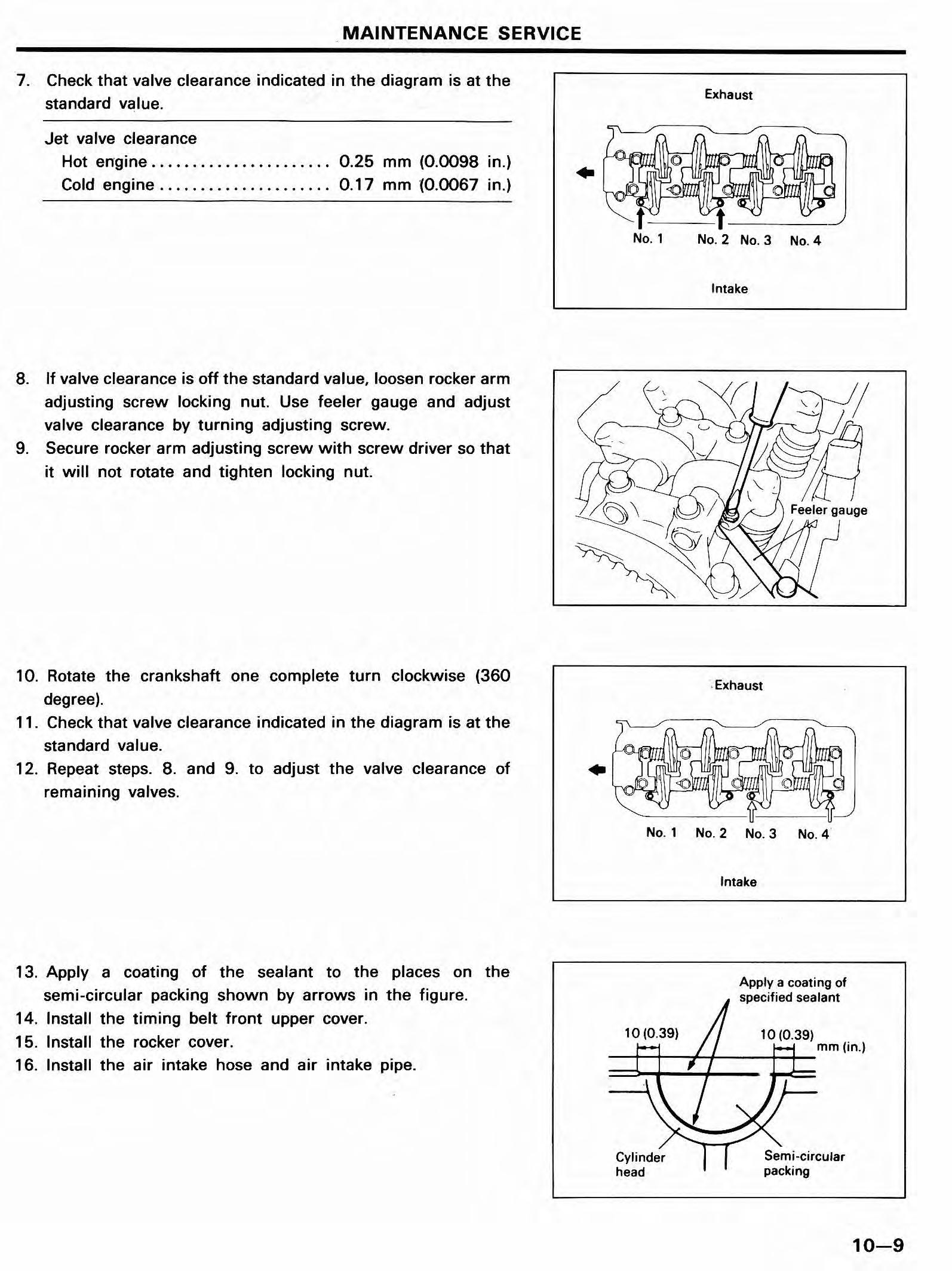
1. Start the engine and allow it to warm up until the temperature of the coolant reaches BOoC to 95°C (176°F to 203°F). 3. Check the ignition timing and idling speed, and adjust if necessary. 4. Remove the rocker cover. 5. Remove timing belt front upper cover. 6. Turn crankshaft clockwise and align with camshaft sprocket timing mark. adjuster
/p/,*
Timing mark Timing mark (on camshaft sprocket) (on cylinder head) ... _
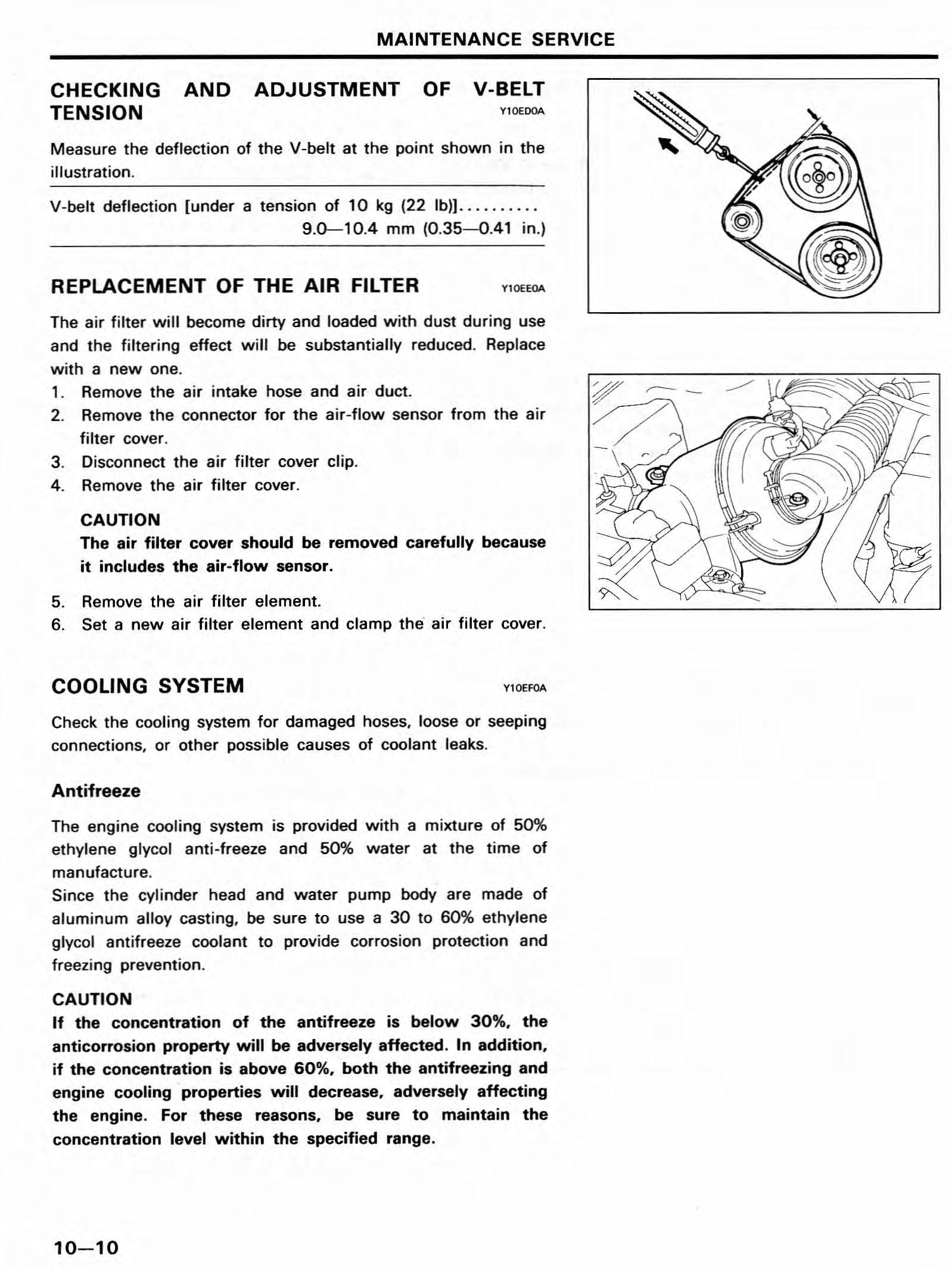
Jet valve clearance
Hot engine
Cold engine 0.25 mm (O.OO98 in.) 0.17 mm (O.OO67 in.)
8. If valve clearance is off the standard value, loosen rocker arm adjusting screw locking nut. Use feeler gauge and adjust valve clearance by turning adjusting screw. 9. Secure rocker arm adjusting screw with screw driver so that it will not rotate and tighten locking nut.
No.1 No.2No.3 No.4
Intake
10. Rotate the crankshaft one complete turn clockwise (360 degree). 11. Check that valve clearance indicated in the diagram is at the standard value. 12. Repeat steps. 8. and 9. to adjust the valve clearance of remaining valves.
13. Apply a coating of the sealant to the places on the semi-circular packing shown by arrows in the figure. 14. Install the timing belt front upper cover. 15. Install the rocker cover. 16. Install the air intake hose and air intake pipe.
.Exhaust
No. 1 No.2 No.3 No.4
Intake
Apply a coating of specified sealant
Cylinder head
CHECKING AND ADJUSTMENT OF V-BELT TENSION Vl0EDOA
Measure the deflection of the V-belt at the point shown in the illustration.
V-belt deflection [under a tension of 10 kg (22 lb)) . 9.0-10.4 mm (0.35-0.41 in.)
REPLACEMENT OF THE AIR FILTER
Y10EEOA
The air filter will become dirty and loaded with dust during use and the filtering effect will be substantially reduced. Replace with a new one. 1. Remove the air intake hose and air duct. 2. Remove the connector for the air-flow sensor from the air fiIter cover. 3. Disconnect the air filter cover clip. 4. Remove the air filter cover.
CAUTION The air filter cover should be removed carefully because it includes the air-flow sensor.
5. Remove the air filter element. 6. Set a new air filter element and clamp the' air filter cover.
COOLING SYSTEM
Y10EFOA
Check the cooling system for damaged hoses, loose or seeping connections, or other possible causes of coolant leaks.
Antifreeze
The engine cooling system is provided with a mixture of 50% ethylene glycol anti-freeze and 50% water at the time of manufacture. Since the cylinder head and water pump body are made of aluminum alloy casting, be sure to use a 30 to 60% ethylene glycol antifreeze coolant to provide corrosion protection and freezing prevention.
CAUTION If the concentration of the antifreeze is below 30%. the anticorrosion property will be adversely affected. In addition. if the concentration is above 60%. both the antifreezing and engine cooling properties will decrease, adversely affecting the engine. For these reasons. be sure to maintain the concentration level within the specified range.
Run the engine until coolant is fully mixed. Drain some coolant (antifreeze), and measure temperature and specific gravity of the coolant. Determine concentration and safe working temperature. If the coolant is short of antifreeze, add antifreeze up to a concentration of 50%.
Replacement the Coolant
1. Set the temperature control level to the hot position. 2. Remove the radiator cap.
CAUTION Remove cap slowly as the system is pressurized and the coolant may be hot.
3. Loosen the drain plug to drain the coolant. 4. Drain the coolant from the reserve tank. 5. After draining the coolant, tighten the drain plug securely. 6. Supply the coolant into the radiator until it is filled up to its filler neck. 7. Supply the coolant into the reserve tank. a. After warming the engine until the thermostat opens, remove the radiator cap and check the coolant level. 9. Supply the coolant into the radiator until it is filled up to its filler neck, and install the radiator cap securely. 10. Fill the reserve tank with coolant up to the "FULL" line.
REPLACEMENT OF IGNITION CABLES Y10EHOA
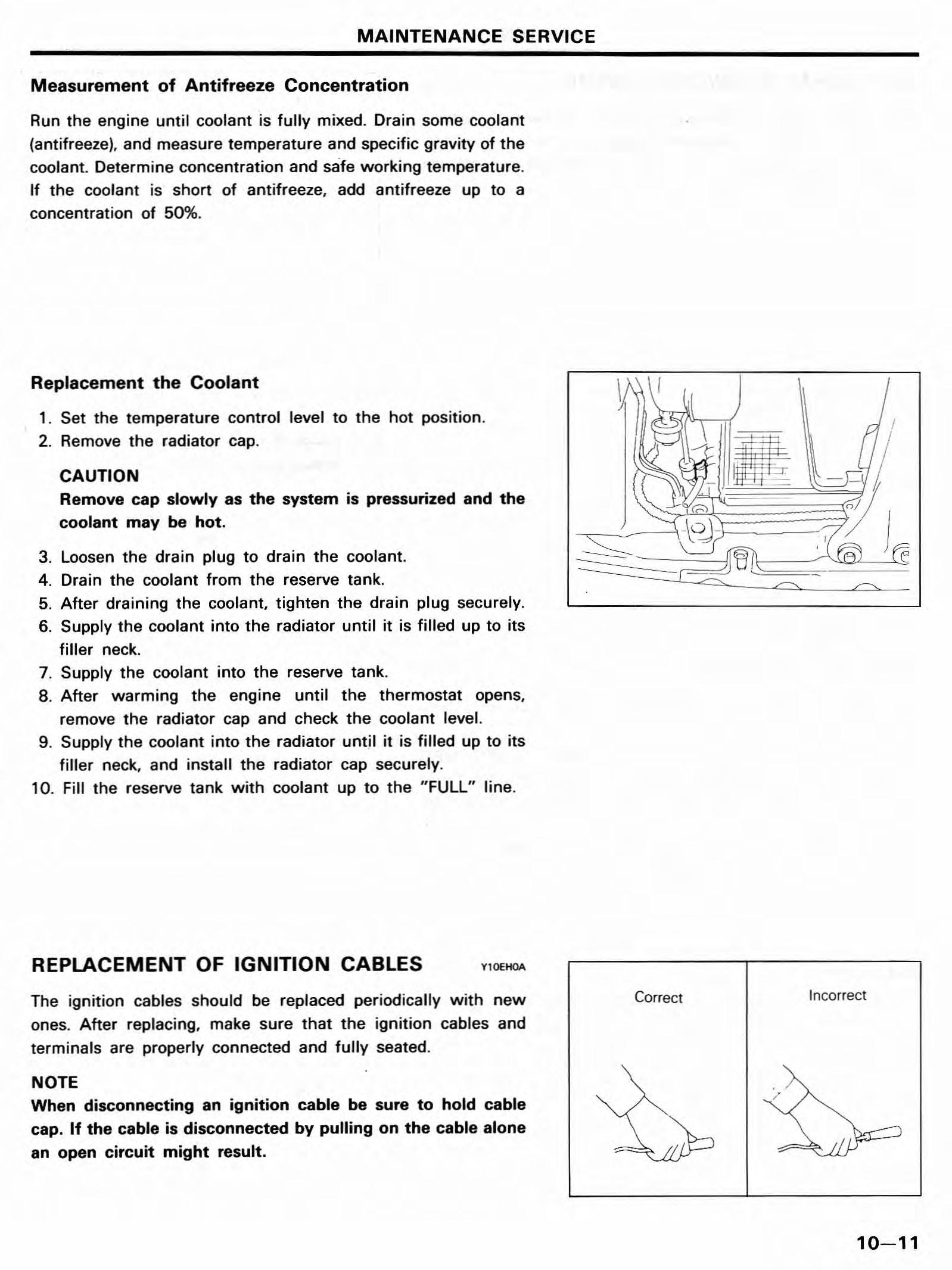
The ignition cables should be replaced periodically with new ones. After replacing, make sure that the ignition cables and terminals are properly connected and fully seated.
NOTE When disconnecting an ignition cable be sure to hold cable cap. If the cable is disconnected by pulling on the cable alone an open circuit might result.
Correct Incorrect
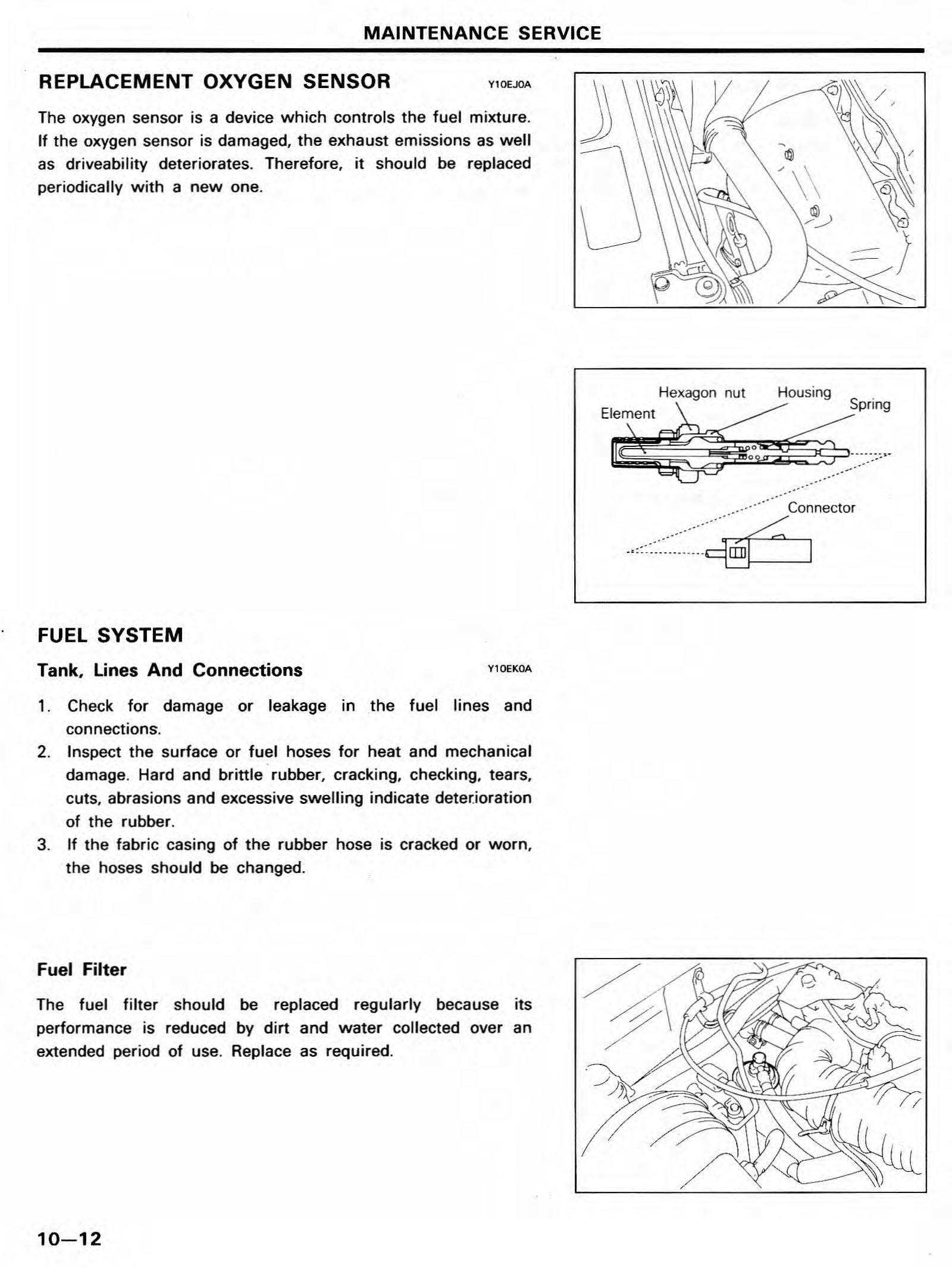
The oxygen sensor is a device which controls the fuel mixture. If the oxygen sensor is damaged, the exhaust emissions as well as driveability deteriorates. Therefore, it should be replaced periodically with a new one.
FUEL SYSTEM
Tank, Lines And Connections
Y10EKOA
1. Check for damage or leakage in the fuel lines and
connections.
2. Inspect the surface or fuel hoses for heat and mechanical damage. Hard and brittle rubber, cracking,checking, tears, cuts, abrasions and excessive swelling indicate deter.ioration of the rubber. 3. If the fabric casing of the rubber hose is cracked or worn, the hoses should be changed.
Fuel Filter
The fuel filter should be replaced regularly because its performance is reduced by dirt and water collected over an extended period of use. Replace as required.
Hexagon nut Housing . ""'
....................:zneclor