
(f)
If mounting on truck carrier, upper must face the rear of the carrier. Position bearing punch mark, located just below the teeth, to the front of the upper. Bearing punch mark·must also align with centerline of the carrier, to allow the swing lock to hold upper in line with carrier.
Carefully lower the upper into place. Engage the studs with the holes in the bearing. Set the upper in place on the carrier or mounting base. Maintain a strain on the sling to keep the upper from tilting. Install a capscrew on each side of each positioning stud. Remove the positioning studs. Install a capscrew in each hole that is accessible. Turn capscrews in by hand until the head just contacts the bearing surface. Then initially tighten each capscrew to 500 ft./ lbs. (668 N•m) torque.
Note: All capscrews lll.lSt be "loctited"asexplained on p�ge 1 before installation.
(g} Start upper engine. Engage master clutch. Release swing lock. Release swing brake. Release the lifting equii:-nent. slowly swing upper until rrore capscrews can be installed. Coat all capscrews with "loctite" as explained on page 1. Continue this procedure until all 38 capscrews are installed, turned in by hand until head contacts bearing surface, then initially tightened to 500 ft/lbs. (668 N,m) torque.
Note: Capscrews should turn in easil)'-:-by hand, until head contacts-bearing surface, If not. check and see why. Damaged threads bent capscrews, capscrew interference. etc., will affect holding power of capscrews and may lead to an accident. Don't use a J>Qwer wrench to run capscrews down,"""l'f" interference does occur, it \loOn"t be noticed.
(h) Now final tighten each capscrew to 1590 to 1750 ft./lbs. (ll24 to 2338 N·m) torque. This is much easier if you use a torque multiplier. See tool list at bottom of page. This wrench has 1 inch input and 1-1/2 inch output drive. It multiplies the torque put on the capscrew times 4.33 to the ft./lbs. that are put into the torque wrench. With this multiplier it is necessary.to only put 367 to 404 ft./lbs. (491 to 540 N•m) torque on the wrench to apply 1590 to 1750 ft./lbs. (2124 to 2338 N·m) on the capscrews.
(i) After final tightening the capscrews1 allow the "loctite" to cure for approximately 6 hours.
(j) Install bearing cover plates.
(k) Assemble live mast. backstops. counterweight, catwalks, and attacllnent on machine. Refer to operators manual for assembly instructions.
yp�r Storage: If the upper is to be stored for a period of time before rrounting. or will set idle
1 - 3Plll-4.33:l Ratio Geared Head Wrench (GA-186)
1 - lPll2-Maptor 1" to 1-1/2" Square Drive (lM-35)
1 - 3P119-Ratchet Wrench W/Hanale 1• Drive (L-73CH)
1 - 3Pl20-Extensfon Bar 10" Long, 1-1/2" Drive (L-105)
1 - 3P121-Adapter 3/4" to 1/2" Drive (LA62)
1 - 3P124-Torque Wrench, 600 ft/lbs. Capacity, 3/4" Drive (TEC-602)
1 - 3P145-Adapter 1" to 3/4" Drive (LA-124)
1 - 3P158-Ratchet Adaptor 1" Drive (L-673)
1 - 3"132-Adaptor 1-1/2" To 1" Sq. Drive
Tool Kit 3P300
1 - 3Pl22-1-13/16" Socket W/1" Square Drive
1 - 3P123-l-7/8"

138A Machines
for long periods of time after mounting. follow storage procedures in operators manuals. In addition, fully lubricate the machine at least every 60 days while in storage. Then start the machine and rotate all shafts, and the turntable bearing to distribute the grease and help prevent rust. This is especially important on machines \loOrking around salt water where rust and corrosion forms faster than usual. In
addition, coat all unpainted metal 3 with preservative. Store machines under cover if at all possible.
Before putting a stored unit to work, thoroughly inspect it for rust, deterioration, damage, etc. Repair any damage befor2 operating the machine.
Preparation For Undecking A Macn,ne: Refer to operatorsiiiariual and perform all of the following steps:
(a) Remove jib, or tip extension from machine. Remove boom from machine.
(b) Remove catwalks from the machine if so equipped.
(c) Remove all counterweights from the machine.
(d) Lower live mast until it is horizontal. Block securely under live mast. Remove boom hoist rope.
(e) Remove live mast from machine.
(f) Remove boom i>ackstops from machine.
Undecking Machine:
(a) If carrier mounted. park machine on firm, level surface. Apply emergency brakes and block wheels.
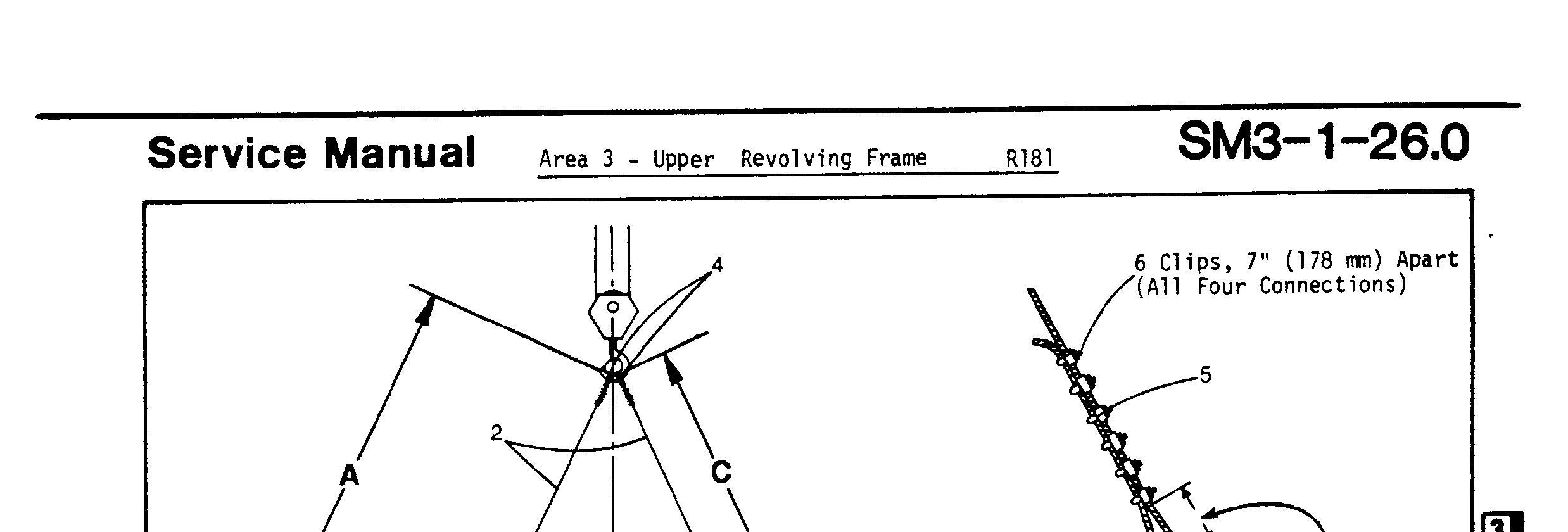
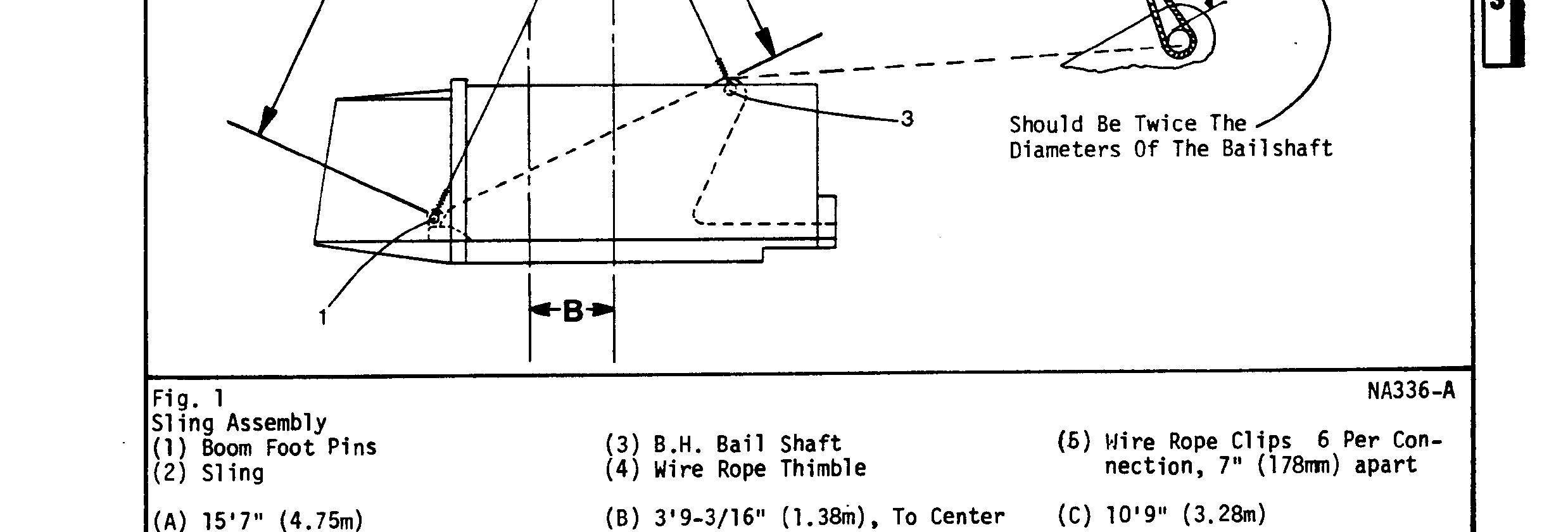
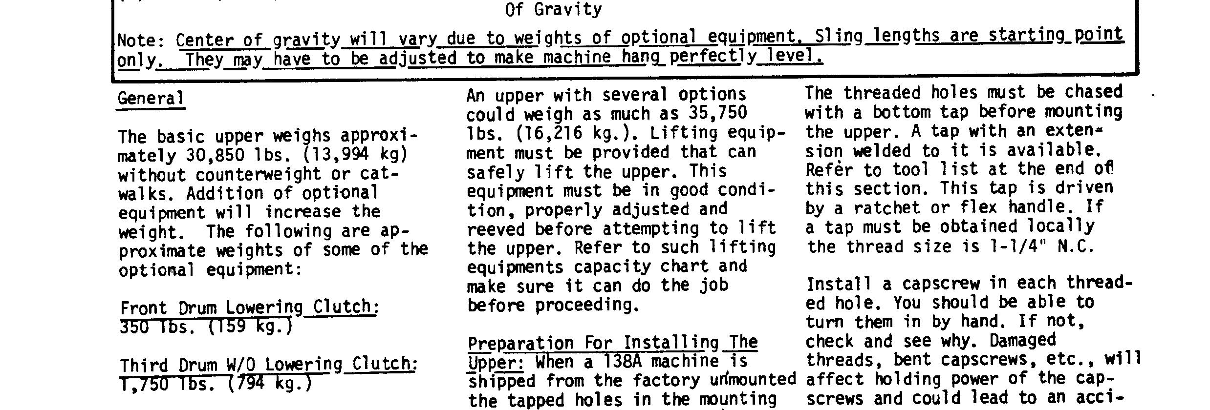
(b) Attach slings to upper. (See Fig. 1.) Connect one leg to each boom foot pin, and one leg to each end of the extended boom hoist bail shaft. (Where the boom backstops mount.) Install keeper pins or cotter pins in the boom foot pins to prevent their working out. Install a large washer. or a plate with a flame cut hole in the center over the bail shaft to prevent the sling slipping off. Install a cotter pin or capscrew and locknut in the hole at each end of the bail shaft to retain the washer or