
HY13-1525-M1/US
TGK Motor Service Procedure
Effective: April 2015
Low Speed High Torque
Hydraulic Motors
HY13-1525-M1/US
Low Speed High Torque, Hydraulic Motors TGK Series
WARNING
FAILURE OR IMPROPER SELECTION OR IMPROPER USE OF THE PRODUCTS AND/OR SYSTEMS DESCRIBED HEREIN OR RELATED ITEMS CAN CAUSE DEATH, PERSONAL INJURY AND PROPERTY DAMAGE.
This document and other information from Parker Hannifn Corporation, its subsidiaries and authorized distributors provide product and/or system options for further investigation by users having technical expertise. It is important that you analyze all aspects of your application and review the information concerning the product or system in the current product catalog. Due to the variety of operating conditions and applications for these products or systems, the user, through its own analysis and testing, is solely responsible for making the fnal selection of the products and systems and assuring that all performance, safety and warning requirements of the application are met.
The products described herein, including without limitation, product features, specifcations, designs, availability and pricing, are subject to change by Parker Hannifn Corporation and its subsidiaries at any time without notice.
© Copyright 2015, Parker Hannifn Corporation, All Rights Reserved
Parker Hannifin Corporation Hydraulic Pump/Motor Division Greeneville, Tennessee USA
Definitions
WARNING A warning describes hazards or unsafe practices which could result in severe personal injury or death.
CAUTION A caution describes hazards or unsafe practices which could result in personal injury or product or property damage.
NOTE A note gives key information to make following a procedure easier or quicker.
Disclaimer
This Service Manual has been prepared by Parker Hannifn Corporation for reference and use by mechanics who have been trained to repair and service hydraulic motors on commercial and non-commercial equipment applications. Parker Hannifn Corporation has exercised reasonable care and diligence to present accurate, clear and complete information and instructions regarding the techniques and tools required for maintaining, repairing and servicing the Parker TGK LSHT Motors. Since this is a general Service Manual, the photographs and illustrations may not look exactly like the motor being serviced. The procedures, therefore, must be carefully read and understood before servicing.
If inspection or testing reveals evidence of abnormal wear or damage to the TGK motor or if you encounter circumstances not covered in the Manual, STOP - CONSULT THE EQUIPMENT MANUFACTURER’S SERVICE MANUAL AND WARRANTY. DO NOT TRY TO REPAIR OR SERVICE A TGK MOTOR WHICH HAS BEEN DAMAGED OR INCLUDES ANY PART THAT SHOWS EXCESSIVE WEAR UNLESS THE DAMAGED AND WORN PARTS ARE REPLACED WITH ORIGINAL PARKER REPLACEMENT AND SERVICE PARTS AND THE UNIT IS RESTORED TO PARKER SPECIFICATIONS FOR THE TGK MOTOR.
It is the responsibility of the mechanic performing the maintenance, repairs or service on a particular motor to (a) inspect the unit for abnormal wear and damage, (b) choose a repair procedure which will not endanger his/her safety, the safety of others, the equipment or the safe operation of the motor, and (c) fully inspect and test the motor and the hydraulic system to ensure that the repair or service of the motor has been properly performed and that the motor and hydraulic system will function properly.
HY13-1525-M1/US Torqmotor Design Features
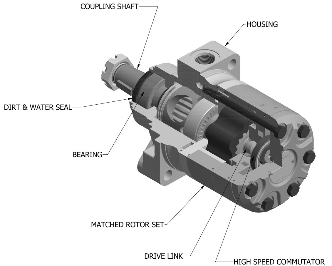
Low Speed High Torque, Hydraulic Motors TGK Series
COUPLINGSHAFT
TGK Series features include:
•Therollervanerotorsetdesignofferslow-frictionandwearcompensationwhichmaximizestheusefulperformance lifeofthemotor.
• Zeroleakcommutationvalveprovidesgreater,moreconsistentvolumetricefficiency.
•Heavydutysplinegeometry.
•Flowthrulubricationprovidescoolingextendingmotorlife.
•Fullinterchangeabilitywithothermotorswhicharedesignedaccordingtoindustrystandards.
•Compatiblewithmosthydraulicsystemswithregardtopressure,torqueandspeed.
•Auniquehigh-pressureshaftsealthateliminatestheneedforcasedrains.
• Up to 45 horsepower output.
•Heavydutyrollerbearingsforhighsideloads.
HY13-1525-M1/US Introduction Introduction
This service manual has one purpose: to guide you in maintaining, troubleshooting and servicing the TGK Torqmotor (low speed, high torque hydraulic motor).
Material in this manual is organized so you can work on the Torqmotor and get results without wasting time or being confused. To get these results, you should read this entire manual prior to beginning work on the Torqmotor.
This manual also contains troubleshooting information and checklist. If you must service the Torqmotor, the checklist will help you to determine where the problem may be.
The three-column format of the Disassembly and Inspection, and Assembly sections will make it easier for you to conduct major work on the Torqmotor. Column 1 gives a brief key for each procedure. Column 2 explains in detail the procedure you should follow. Column 3 illustrates this procedure with photographs. Read all information carefully and pay special attention to the notes, cautions and warnings.
Low Speed High Torque, Hydraulic Motors TGK Series
A page the with exploded assembly view is provided several places in this manual. The component part names and item numbers assigned on this exploded assembly view correspond with names and item numbers (in parentheses) used in the disassembly and assembly procedures set forth in this manual.
Service part list charts are also provided in this manual with the part names and exploded view item numbers cross referenced to Parker service part numbers. Service parts are available through the Original Equipment Manufacturer or Parker approved TGK Distributors.
As you gain experience in servicing the Torqmotor, you may fnd that some information in this manual could be clearer or more complete. If so, let us know about it. Do not try to second guess the manual. If you are stuck, contact us. Servicing the Torqmotor should be a safe and productive procedure, in order for the unit to deliver the reliable, long-life operation engineered into it.
HY13-1525-M1/US Troubleshooting Guide
Troubleshooting Guide
NOTE Before troubleshooting any system problem, check service literature published by the equipment and/or component manufacturers. Follow their instructions, if given, for checking any component other than the Torqmotor unit.
Preparation
Make your troubleshooting easier by preparing as follows:
• work in a clean, well-lighted place
• have proper tools and materials nearby
• have an adequate supply of clean, petroleum-based solvent
Since solvents are fammable, be extremely careful when using any solvent. Even a small explosion could cause injury or death.
Wear eye protection and be sure to comply with OSHA and other maximum air pressure requirements.
Preliminary Checks
Hydraulic systems are often trouble-free. Hence, the problem an operator complains of could be caused by something other than the hydraulic components.
Thus, once you have determined that a problem exists, start with the easy-to-check items, such as:
• Parts damaged from impact that were not properly repaired, or that should have been replaced
• Improper replacement parts used in previous servicing
• Mechanical linkage problems such as binding, broken or loose parts, or slipping belts
Low Speed High Torque, Hydraulic Motors TGK Series
Hydraulic Components
If you think the problem is caused by a hydraulic component, start by checking the easy-to-reach items.
Check all hoses and lines for cracks, hardening or other signs of wear. Reroute any usable hoses that are kinked, severely bent, or that rest against hot parts. Look for leaks, especially at couplings and fttings. Replace any hoses or lines that don’t meet system fow and pressure ratings.
Next, go to the reservoir and flters. Check fuid level and look for air bubbles. Check the flter(s). A flter with a maximum of 20 micron fltration is recommended for the Torqmotor system.
Visually check other components to see if they are loosely mounted, show signs of leaks, or other damage or wear.
Excessive heat in a hydraulic system can create problems that can easily be overlooked. Every system has its limitation for the maximum amount of temperature. After the temperature is attained and passed, the following can occur:
• oil seal leaks
• loss of effciency such as speed and torque
• pump loss of effciency
• pump failure
• hoses become hard and brittle
• hose failure
A normal temperature range means an effcient hydraulic system. Consult the manuals published by equipment and/or component manufacturers for maximum allowable temperatures and hydraulic tests that may be necessary to run on the performance of the hydraulic components. The Torqmotor is not recommended for hydraulic systems with maximum temperatures above 200o F (93.3o C).
HY13-1525-M1/US
Troubleshooting Checklist
Low Speed High Torque, Hydraulic Motors TGK Series
OilLeakage
1.Hosefittingsloose,wornor damaged
2.Oilsealrings(5)deterioratedby excessheat.
3.Specialbolt(1) looseoritssealingarea deterioratedbycorrosion
4.Internalshaftseal(18)wornor damaged
5. Worncouplingshaft(14)and internalseal(18)
Significantlossof speedunderload
1.Lackofsufficientoilsupply
Check & replacedamaged fittingsor “O” Rings.Torque to manufacturersspecifications
Replaceoilsealringsbydisassembling Torqmotorunit
(a)Loosenthentightensingleboltto torque specification
(b) Replacebolt
Replaceseal.Disassemblyof Torqmotorunit necessary.
Replacecouplingshaftandsealby disassembling Torqmotorunit.
(a)Checkforfaultyreliefvalveand adjustorreplaceasrequired.
(b) Check forandrepairwornpump
(c)Checkforandusecorrectoilfor temperatureofoperation
Lowmechanical efficiencyorundue highpressure requiredtooperate Torqmotorunit
2. Highinternalmotorleakage
3. Severelywornordamaged internalsplines
4.Excessiveheat.
1. Lineblockage
2. Internalinterference
3. Lackofpumpingpressure
4.Excessive bindingorloadingin systemexternalto Torqmotor unit
Replacewornrotorset bydisassembling Torqmotorunit
Replacerotorset,drivelinkandcoupling shaftby disassembling Torqmotor unit.
Locateexcessiveheatsource(usuallya restriction)inthesystemandcorrectthe condition
Locate blockage source and repairor replace
Disassemble Torqmotorunit, identify and remedycauseandrepair,replacingpartsas necessary.
Check forandrepairwornpump
Locatesourceandeliminatecause.
CAUTION:Ifthehydraulicsystemfluidbecomesoverheated[inexcessof200°F (93.3°C)],sealsinthesystem canshrink,hardenorcrack,thuslosingtheirsealingability.
Parker
HY13-1525-M1/US
Tools & Materials Required for Servicing
Low Speed High Torque, Hydraulic Motors
TGK Series
Tools and Materials Required for Servicing
• Clean, petroleum-based solvent
• Emery paper
• Vice with soft jaws
• Air-pressure source
• Arbor press
• Flat screwdriver
• Masking tape
• Breaker bar
• 1/4" torque wrench
CAUTION
Mixing greases that have different bases can be detrimental to bearing life.
• Sockets: 1/2 or 9/16 inch thin wall, 1 inch
• Allen wrenches: 3/16, 3/8 inch
• Adjustable crescent wrench or hose ftting wrenches
• SAE 10W40 SE or SF oil
• Special bearing mandrel for TGK Torqmotor (See Figure 1)
• Feeler gage .005 inch (.13 mm)
• |GK Torqmotor requires blind hole bearing puller for a 1.750 inch dia. (44.45 mm) and 2.750 inch dia. (69.85 mm)
• Clean corrosion resistant grease. Part #406018 is included in each seal kit. Recommended grease is Parker Specifcation #045236 or Mobil Mobilith SHC® 460.
Low Speed High Torque, Hydraulic Motors
TGK Series
HY13-1525-M1/US Exploded View
Typical Assembly
Low Speed High Torque, Hydraulic Motors TGK Series
ASSEMBLE COMMUTATOR SEAL WITH WEDGE SIDE DOWN INTO COMMUTATOR FACE
Parker Hannifin Corporation Hydraulic Pump/Motor Division Greeneville, Tennessee USA
HY13-1525-M1/US Service Parts List
Chart Use Example:
Low Speed High Torque, Hydraulic Motors TGK Series
S (PORTING), 08 (SHAFT), 0 (ROTATION), and AAAB (OPTION) shown in the left hand column of the chart.
TGK0240US080AAAB Torqmotor includes part numbers listed to the right of TGK (SERIES), 0240 (DISP.), U
Caution:
The charted component service information is for the Torqmotors listed only. Refer to the original equipment manufacturer of the equipment using the Torqmotor for assembly numbers not listed below.
HY13-1525-M1/US Service Parts List
Low Speed High Torque, Hydraulic Motors
TGK Series
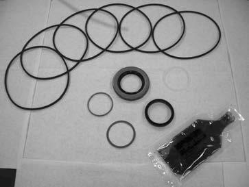
Standard Buna seal kit SK000323 includes six #032870 seal rings, #032435 commutator seal, #032817 shaft seal, #028515 Back Up Ring, #029118 Back Up Washer, #478035 dirt & water seal, #406018 grease pack and bulletin #050099.
Fulorocarbon seal kit SK000324 includes six #032869 seal rings, #032435 commutator seal, #032818 shaft seal, #028515 Back Up Ring, #029118 Back Up Washer, #478035 dirt & water seal, #406018 grease pack and bulletin #050099.
Fulorocarbon & Hi-Temp Commutator seal kit SK000325 includes six #032869 seal rings, #032861 commutator seal, #032818 shaft seal, #028515 Back Up Ring, #029118 Back Up Washer, #478035 dirt & water seal, #406018 grease pack and bulletin #050099.
Hi-Temp Commutator seal kit SK000333 includes six #032870 seal rings, #032861 commutator seal, #032817 shaft seal, #028515 Back Up Ring, #029118 Back Up Washer, #478035 dirt & water seal, #406018 grease pack and bulletin #050099
TGK018001A1 commutator assemby is required if the designated option group is for rear porting.
HY13-1525-M1/US Disassembly and Inspection
PreparationBeforeDisassembly
Low Speed High Torque, Hydraulic Motors TGK Series
•BeforeyoudisassembletheTorqmotorunitoranyofitscomponentsreadthisentiremanual.Itprovidesimportant informationonpartsandproceduresyouwillneedtoknowtoservicetheTorqmotor.
•Referto“ToolsandMaterialsRequiredforServices”sectionfortoolsandotheritemsrequiredtoservicethe Torqmotorandhavethemavailable.
•Thoroughlycleanoffalloutsidedirt,especiallyfromaroundfittingsandhoseconnections,beforedisconnecting andremovingtheTorqmotor.Removerustorcorrosionfromcouplingshaft.
•Removecouplingshaftconnectionsandhosefittingsandimmediatelyplugportholesandfluidlines.
•RemovetheTorqmotorfromsystem,drainitoffluidandtakeittoacleanworksurface.
•CleananddrytheTorqmotorbeforeyoustarttodisassembletheunit.
•AsyoudisassembletheTorqmotorcleanallparts,exceptseals,incleanpetroleum-basedsolvent,andblowthem dry.
WARNING:petroleum-basesolventsareflammable.Beextremelycarefulwhenusinganysolvent.Evenasmall explosionorfirecouldcauseinjuryordeath.
WARNING:WEAREYEPROTECTIONANDBESURETOCOMPLYWITHOSHAOROTHERMAXIMUMAIR PRESSUREREQUIREMENTS.
CAUTION:Neversteamorhighpressurewashhydrauliccomponents.Donotforceorabusecloselyfittedparts.
•Keeppartsseparatetoavoidnicksandburrs.
•DiscardallsealsandsealringsastheyareremovedfromtheTorqmotor.Replaceallseals,sealringsandany damagedorwornpartswithgenuineParkerorOEMapprovedserviceparts.
CAUTION: Special lifting aids may be required to handle/service the TGK motor due to it’s large size and weight. Take steps necessary to ensure that handling/service can be done safely.
HY13-1525-M1/US Disassembly and Inspection
Place Torqmotor in a vise WARNING
Low Speed High Torque, Hydraulic Motors TGK Series
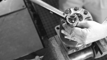
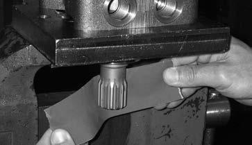
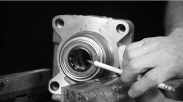
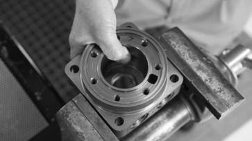
1. Place the Torqmotor in a soft jawed vise or similar support, with coupling shaft (12) pointed down and the vise jaws clamping frmly on the sides of the housing (19) mounting fange. SEE FIGURE 1.
WARNING IF THE TORQMOTOR IS NOT FIRMLY HELD IN THE VISE, IT COULD BE DISLODGED DURING THE SERVICE PROCEDURES, CAUSING INJURY.
Scribe alignment mark
2. Scribe an alignment mark down and across the Torqmotor components from end cover (2) to housing (19) to facilitate reassembly orientation where required. SEE FIGURE 2.
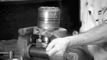
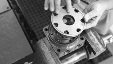
Remove special bolts & inspect bolts
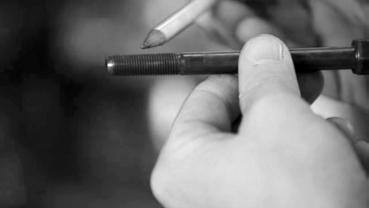
3. Remove the seven special hex head bolts (1) using a 9/16 inch size socket. SEE FIGURE 3. Inspect bolts for damaged threads. Replace damaged bolts. SEE FIGURE 4.
HY13-1525-M1/US Disassembly and Inspection
Remove end cover
Low Speed High Torque, Hydraulic Motors TGK Series
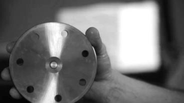
4. Remove end cover (2). SEE FIGURE 5.
Wash & inspect end

5. Thoroughly wash end cover (2) in proper solvent and blow dry. Be sure the end cover fow areas are free of contamination. Inspect end cover for cracks and the bolt head recesses for damage. Replace end cover as necessary. SEE FIGURE 6.
NOTE
A polished pattern (not scratches) on the cover from rotation of the commutator is normal. Discoloration would indicate excess fluid temperature, thermal shock, or excess speed and require system investigation for cause and close inspection of end cover, commutator, manifold, and rotor set.
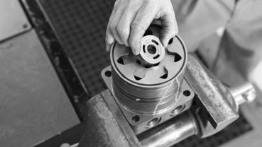
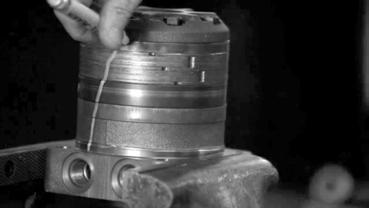
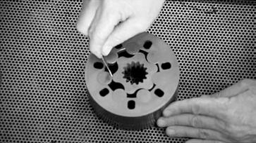
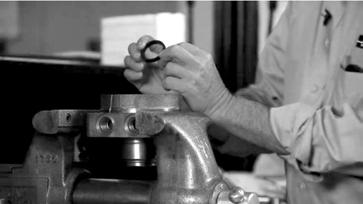
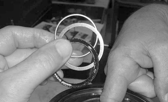
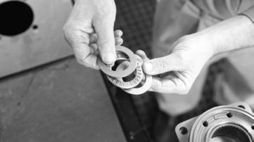
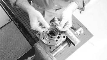
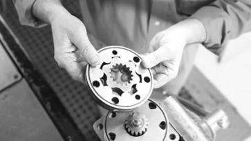
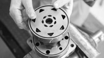
6. Remove commutator and seal ring (4) Remove seal ring from commutator, using an air hose to blow air into ring groove until seal ring is lifted out and discard seal ring. Inspect commutator for cracks or burrs, wear, scoring, spalling or brinelling. If any of these conditions exist, replace commutator.
SEE FIGURES 7 and 8.
HY13-1525-M1/US Disassembly and Inspection
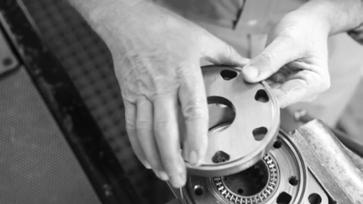
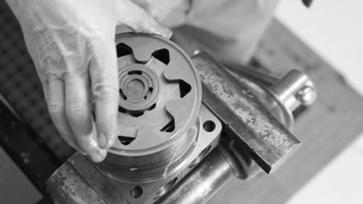
Remove manifold
Low Speed High Torque, Hydraulic Motors TGK Series
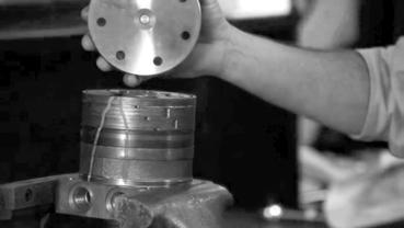
7. Remove manifold (6) and inspect for cracks surface scoring, brinelling or spalling. Replace manifold if any of these conditions exist. SEE FIGURE 9. A polished pattern on the ground surface from commutator or rotor rotation is normal. Remove and discard the seal ring (3).
NOTE
The manifold is constructed of plates bonded together to form an integral component not subject to further disassembly for service.
Compare configuration of both sides of the manifold to ensure that same surface is reassembled against the rotor set.
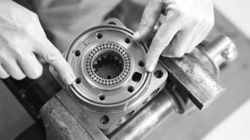
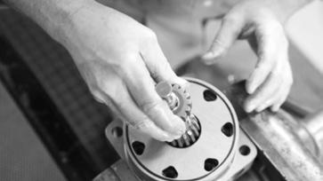
Remove & inspect rotor set & wearplate
8. Remove rotor set (7) and wearplate (8), inspect together to retain the rotor set in its assembled form, maintaining the same rotor vane to stator contact surfaces.
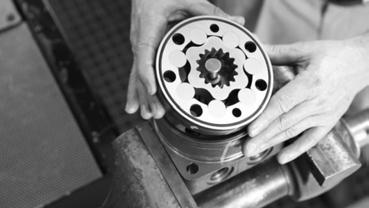

SEE FIGURE 10.
The drive link (9) may come away from the coupling shaft (12) with the rotor set, and wearplate. You may have to shift the rotor set on the wearplate to work the drive link out of the rotor and wearplate. Inspect the rotor set in its assembled form for nicks, scoring, or spalling on any surface and for broken or worn splines. If the rotor set component requires replacement, the complete rotor set must be replaced as it is a matched set. Inspect the wearplate for cracks, brinelling, or scoring.
SEE FIGURE 11.
Discard seal rings (3) between the rotor set, and the wearplate.
NOTE
The rotor set (7) components may become disassembled during service procedures. Marking the surface of the rotor and stator that is facing UP, with etching ink or grease pencil before removal from Torqmotor will ensure correct reassembly of rotor into stator and rotor set into Torqmotor. Marking all rotor components and mating spline components for exact repositioning at assembly will ensure maximum wear life and performance of rotor set and Torqmotor.
HY13-1525-M1/US Disassembly and Inspection
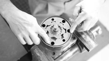
Low Speed High Torque, Hydraulic Motors TGK Series
Series TGK Torqmotor may have a rotor set with two stator halves with a seal ring (3) between them. Discard seal ring only if stator halves become disassembled during the service procedures.
A polished pattern on the wear plate from rotor rotation is normal.

9. Place rotor set (7) and wear plate (8) on a fat surface and center rotor in stator such that two rotor lobes (180 degrees apart) and a roller vane centerline are on the same stator centerline. Check the rotor lobe to roller vane clearance with a feeler gage at this common centerline. If there is more than .005 inches (0.13 mm) of clearance, replace rotor set. SEE FIGURE 12.
If rotor set (7) has two stator halves, check the rotor lobe to roller vane clearance at both ends of rotor.
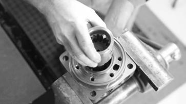
10. Remove drive link (9) from coupling shaft (12) if it was not removed with rotor set and wear plate. Inspect drive link for cracks and worn or damaged splines. No perceptible lash (play) should be noted between mating spline parts. SEE FIGURES 13 and 14.
11. Remove and discard seal ring (3) from housing (19). SEE FIGURE 15.
HY13-1525-M1/US Disassembly and Inspection
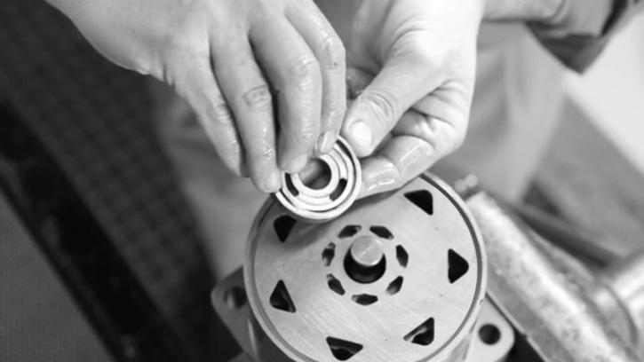
Remove thrust bearing
Low Speed High Torque, Hydraulic Motors TGK Series
12. Remove rear thrust bearing (11) and retaining bearing washer (10) from top of coupling shaft (12). Inspect for wear, brinelling, corrosion and a full complement of retained rollers.
SEE FIGURE 16.
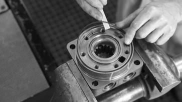
Check coupling shaft for rust or corrosion
12. Check exposed portion of coupling shaft (12) shaft for rust to be sure you have removed all signs of rust or corrosion which might prevent its withdrawal through the seal and bearing. Crocus cloth or fne emery paper may be used. Remove any key (28), nut (29A), washer, bolt, or lock washer still attached to the shaft.
SEE FIGURE 17.
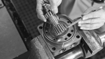
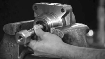
Remove & inspect coupling shaft
13. Remove coupling shaft (12), by pushing on the output end of shaft. SEE FIGURE 18. Inspect bearing and seal surfaces for spalling, nicks, grooves, severe wear or corrosion and discoloration. Inspect for damaged or worn internal and external splines or keyway. SEE FIGURE 19. Replace coupling shaft if any of these conditions exist.
NOTE NOTE
Minor shaft wear in seal area is permissible. If wear exceeds .020 inches (0.51 mm) diametrically, replace coupling shaft.
A slight “polish” is permissible in the shaft bearing areas. Anything more would require coupling shaft replacement.
HY13-1525-M1/US Disassembly and Inspection
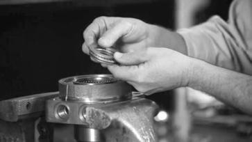
Remove shaft seal, backup washer and backup ring
Remove dirt & water seal
Low Speed High Torque, Hydraulic Motors TGK Series
15. Remove shaft seal (16), backup washer (17), and backup ring (18) from TGK Series Torqmotor housing. Discard shaft seal and washers. SEE FIGURE 20.
Inspect housing assembly
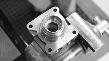
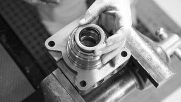
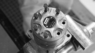
16. Remove housing (19) from vise, invert it and remove and discard dirt and water seal (21). A blind hole bearing or seal puller is required. SEE FIGURE 21
17. Inspect housing (19) assembly for cracks, the machined surfaces for nicks, burrs, brinelling or corrosion. Remove burrs that can be removed without changing dimensional characteristics. Inspect tapped holes for thread damage. SEE FIGURE 22. If the housing is defective in these areas, discard the housing assembly.
HY13-1525-M1/US Disassembly and Inspection
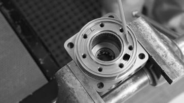
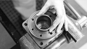
Inspect housing bearings
NOTE
Low Speed High Torque, Hydraulic Motors TGK Series
18. If the housing (19) assembly has passed inspection to this point, inspect the housing bearings (20) and (13) and since they are captured in the housing cavity, the two thrust washers (14) and thrust bearing (15). The bearing rollers must be frmly retained in the bearing cages, but must rotate and orbit freely. All rollers and thrust washers must be free of brinelling and corrosion. SEE FIGURE 23.
The depth or location of bearing (13) in relation to the housing wear plate surface should be measured and noted before removing the bearings. This will facilitate the correct reassembly of new bearings.

Remove bearings
19. If the bearings must be replaced use a suitable size bearing puller to remove bearing (13) from housing (19) without damaging the housing. SEE FIGURE 24.
THE DISASSEMBLY OF TORQMOTOR IS NOW COMPLETE.
HY13-1525-M1/US Torqmotor Assembly
Low Speed High Torque, Hydraulic Motors TGK Series
• Replace all seals and seal rings with new ones each time you reassemble the Torqmotor unit. Lubricate seals and seal rings with clean recommended grease, Parker Gear grease specifcation #045236, E/M Lubricant #K70M or Mobil Mobilith SHC® 460. A packet of grease (P/N 406018) is included in each seal kit.
• NOTE: Complete seal kits are available. SEE FIGURE 25. The parts should be available through most OEM parts distributors or Parker approved Torqmotor distributors. (Contact your local dealer for availability).
• NOTE: Unless otherwise indicated, do not oil or grease parts before assembly.
• Wash all parts in clean petroleum-based solvents before assembly. Blow them dry with compressed air. Remove any paint chips from mating surfaces of the end cover, commutator set, manifold rotor set, wear plate and housing and from port and sealing areas.
WARNING WARNING
SINCE THEY ARE FLAMMABLE, BE EXTREMELY CAREFUL WHEN USING ANY SOLVENT. EVEN A SMALL EXPLOSION OR FIRE COULD CAUSE INJURY OR DEATH.
WEAR EYE PROTECTION AND BE SURE TO COMPLY WITH OSHA OR OTHER MAXIMUM AIR PRESSURE REQUIREMENTS.
Place housing into soft-jawed vise
1. Clamp the housing into a soft-jawed vise or similar support, clamping against the mounting fange. SEE FIGURE 26.
HY13-1525-M1/US Torqmotor Assembly
Press in outer bearing
NOTE CAUTION
Low Speed High Torque, Hydraulic Motors TGK Series
2. If the housing (19) bearing components were removed for replacement, thoroughly coat and pack a new outer bearing (20) with clean corrosion resistant grease recommended in the material section. Press the new bearing into the counterbore at the mounting fange end of the housing, using the appropriate sized bearing mandrel such as described in fgure 1 which will control the bearing depth to .410/.420” from the outside face of the counter bore. SEE FIGURE 27.
Bearing mandrel must be pressed against the lettered end of bearing shell. Take care that the housing bore is square with the press base and the bearing is not cocked when pressing a bearing into the housing.
If the bearing mandrel specified in the “Tools and Materials Required for Servicing” section is not available and alternate methods are used to press in bearing (13) or (20) be careful to ensure that the bearing depths specified are achieved to insure adequate bearing support and correct relationship to adjacent components when assembled.
CAUTION
Because bearings (13) and (20) have a press fit into the housing they must be discarded when removed. They must not be reused.
CAUTION
The outer bearing (20) is not lubricated by the system’s hydraulic fluid. Be sure it is thoroughly packed with the recommended grease, Parker Gear grease specification #045236, E/M Lubricant #K- 70M or Mobil Mobilith SHC ® 460 A packet of grease (P/N 406018) is included in each seal kit.
HY13-1525-M1/US Torqmotor Assembly
Press in dirt & water seal
Low Speed High Torque, Hydraulic Motors TGK Series
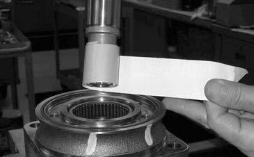
3. Press a new dirt and water seal (21) into the housing (19) outer bearing counterbore. The dirt and water seal (21) must be pressed in with the lip facing out and until the seal is fush to .020 inches (.51 mm) below the end of housing. SEE FIGURE 28.
Place housing assembly into vise
4. Invert housing (19) assembly into a soft jawed vise or similar support with the coupling shaft bore down, clamping against the mounting fange. SEE FIGURE 29.
Press in inner bearing and assemble washers & seal
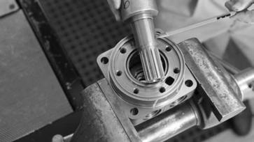
5. If the housing (19) bearing components were removed for replacement, press new bearing (13) into the housing (19) to a depth of .130/.150 inches. Use the opposite end of the bearing mandrel used to press in outer bearing (20). Reference fgure 1, in the “Tools and Materials Required for Servicing” section. SEE FIGURE 30.
Assemble new backup ring (18), a new backup washer (17), new seal (16), with the lip facing to the inside of Torqmotor (see fgure 45). SEE FIGURES 31 & 32.
HY13-1525-M1/US Torqmotor Assembly
Assemble thrust washers and thrust bearing CAUTION
Low Speed High Torque, Hydraulic Motors TGK Series
6. Assemble a thrust washer (14), thrust bearing (15) and a second thrust washer (14) in that order. SEE FIGURE 33.
Be sure the thrust bearing package is seated in the correct order after assembly of the new shaft seal and new backup washer and backup ring.
Apply masking tape to shaft
7. Apply masking tape around splines or keyway on shaft (12) to prevent damage to seal. SEE FIGURE 34.
Install coupling shaft
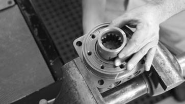
8. Be sure that a generous amount of clean corrosion resistant grease has been applied to the lower (outer) housing bearing (20). Install the coupling shaft (12) into housing (19), seating it against the second thrust washer (14). SEE FIGURE 35.
The coupling shaft (12) will be approximately .10 inch (2.54 mm) below the housing wear plate surface when correctly installed to allow the assembly of thrust bearing (11) and retaining washer (10). The coupling shaft must rotate smoothly on the thrust bearing package.
HY13-1525-M1/US Torqmotor Assembly
Install thrust bearing and retaining washer
Low Speed High Torque, Hydraulic Motors TGK Series
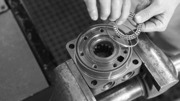
9. Install thrust bearing (11) and retaining washer (10) onto the end of coupling shaft (12). SEE FIGURE 36.
Insert seal ring
10. Install a new seal ring (3) into the housing (19) seal ring groove. SEE FIGURE 37.
Assemble wear plate and seal ring
11. Assemble wear plate (8) onto the housing (19). SEE FIGURE 38. Install a new seal ring (3) and assemble it into the seal ring groove on the wear plate.
HY13-1525-M1/US Torqmotor Assembly
Install drive link NOTE
Low Speed High Torque, Hydraulic Motors TGK Series
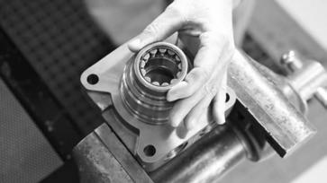
12. Install drive link (9) with the long splined end down into the coupling shaft (12) and engage the drive link splines into mesh with the coupling shaft splines.
SEE FIGURE 39.
Use any alignment marks put on the coupling shaft and drive link before disassembly to assemble the drive link splines in their original position in the mating coupling shaft splines.
13. Install the assembled rotor set (7) onto wear plate (8) with rotor counterbore side down and the splines into mesh with the drive link splines.
SEE FIGURES 40 and 41. Install a new seal ring (3) and into the seal ring groove in the rotor set (7).

SEE FIGURE 42.
HY13-1525-M1/US Torqmotor Assembly
NOTE
Low Speed High Torque, Hydraulic Motors TGK Series
The manifold (6) is made up of several plates bonded together permanently to form an integral component. The manifold surface that must contact the rotor set has it’s series of irregular shaped cavities on the largest circumference or circle around the inside diameter. The polished impression left on the manifold by the rotor set is another indication of which surface must contact the rotor set.
Install manifold and seal ring
14. Assemble the manifold (6) over the drive link (9) and onto the rotor set. Be sure the correct manifold surface is against the rotor set. SEE FIGURE 43. Install a new seal ring (3) and in the seal ring groove exposed on the manifold.
Assemble seal & commutator
15. Assemble a new seal ring (4) fat side up, into commutator (5) and assemble commutator over the end of drive link (9) onto manifold (6) with seal ring side up. SEE FIGURE 44.
Install commutator ring
16. Assemble the commutator ring (5) onto the manifold. SEE FIGURE 45. Install a new seal ring (3) and in the seal ring groove exposed on the commutator ring.
HY13-1525-M1/US Torqmotor Assembly
Assemble end cover
Low Speed High Torque, Hydraulic Motors TGK Series
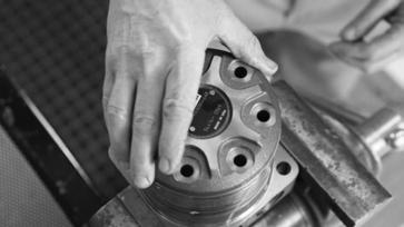
19. Assemble end cover (2) over the commutator and in line with the alignment marks on the exterior of the motor.
SEE FIGURE 46.
Assemble cover bolts
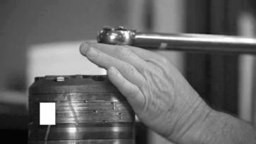
20. Insert the bolts through the end cover until threads of each bolt reach the proper threaded hole of the housing. Hand start each bolt. Alternately and progressively tighten the bolts to pull the end cover and other components into place with a fnal torque of 45-55 ft. lbs.
SEE FIGURES 47 and 48.
THE ASSEMBLY OF THE TORQMOTOR IS NOW COMPLETE EXCEPT FOR KEY (28), NUT (29), or OTHER EXTERNAL HARDWARE IF APPLICABLE. PROCEED TO FINAL CHECKS SECTION.
HY13-1525-M1/US
Final Checks
Final Checks
Low Speed High Torque, Hydraulic Motors TGK Series
• Pressurize the Torqmotor with 100 PSI dry air or nitrogen and submerge in solvent to check for external leaks. Make sure to plug the remaining ports prior to submerging.
• Check Torqmotor for rotation. Torque required to rotate coupling shaft should not be more than 50 lb/ft (68 N m).
• On TGK Series Torqmotor, pressure port with "A" cast under it on endcover (2) is for clockwise coupling shaft rotation as viewed from the output end of coupling shaft. Pressure port with "B" cast under it for counter clockwise coupling shaft rotation.
• Use test stand if available, to check operation of the Torqmotor.
Hydraulic Fluids
Keep the hydraulic system flled with one of the following:
• 10W40 SE or SF, or manufacturer’s suggested oil.
• Hydraulic fuid as recommended by equipment manufacturer, but the viscosity should not drop below 50 SSU or contain less than .125% zinc anti-wear additives.
CAUTION Do not mix oil types. Any mixture, or an unapproved oil could deteriorate the seals. Maintain the proper fuid level in the reservoir. When changing fuid, completely drain old oil from the system. It is suggested also that you fush the system with clean oil.
Filtration
Recommended fltration 20-50 micron.
Oil Temperature
Maximum operating temperature 200o F (93.3o C).
HY13-1525-M1/US
System Maintenance Tips
• Adjust fuid level in reservoir as necessary.
Low Speed High Torque, Hydraulic Motors TGK Series
• Encourage all operators to report any malfunction or accident that may have damaged the hydraulic system or component.
• Do not attempt to weld any broken Torqmotor component. Replace the component with original equipment only.
• Do not cold straighten, hot straighten, or bend any Torqmotor part.
• Prevent dirt or other foreign matter from entering the hydraulic system. Clean the area around the fller caps before checking oil level.
• Investigate and correct any external leak in the hydraulic system, no matter how minor the leak.
• Comply with manufacturer’s specifcations for cleaning or replacing the flter.
CAUTION Do not weld, braze, solder or in any way alter any Torqmotor component.
CAUTION Maximum operating pressure must not exceed recommended Torqmotor pressure capacity.
CAUTION Always carefully inspect any system component that may have been struck or damaged during operation or in an accident. Replace any component that is damaged or that is questionable.
CAUTION Do not force any coupling onto the Torqmotor coupling shaft as this could damage the unit internally.
Parker Pump/Motor Operation extends close technical cooperation and assistance. If problems occur which you cannot solve, please contact our service department at (423) 639-8151, or your local Parker approved distributor.
HY13-1525-M1/US