Cambridge International AS and A level Computer Science
tones but a printer at any position on a page could only print black or nothing. The solution to this was halftoning. This technique approximated a grey tone by printing an array of black dots; varying the size of the dots changed the tone displayed. The technique, of course, relies on the limitations of the human eye which does not register the individual dots if they are sufficiently small. A variation of this technique is used in computer graphic presentation. Normally, neither screen nor printer technology can produce varying size dots but the same effect can be produced by varying the number of dots created in what can be described as a halftone cell. It is now standard practice for grey-scale images or colour images to be presented using a halftoning technology. This requires a raster image processor, which can be a combination of hardware and software, to control the conversion of data stored in a graphics file to the physical screen display or printed page.
3.05 Screens and associated technologies Screen technology associated with computer systems has a long evolutionary history. For many years the only example was the visual display unit (VDU) which was used as a computer monitor or terminal. The VDU employed the cathode ray tube (CRT) technology used in a television set but the functionality offered by the device was limited to recording keyboard input and displaying text output.
Computer mouse 42
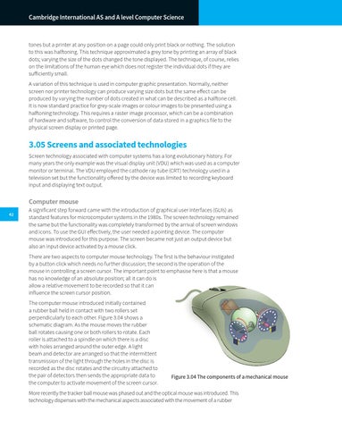
A significant step forward came with the introduction of graphical user interfaces (GUIs) as standard features for microcomputer systems in the 1980s. The screen technology remained the same but the functionality was completely transformed by the arrival of screen windows and icons. To use the GUI effectively, the user needed a pointing device. The computer mouse was introduced for this purpose. The screen became not just an output device but also an input device activated by a mouse click. There are two aspects to computer mouse technology. The first is the behaviour instigated by a button click which needs no further discussion; the second is the operation of the mouse in controlling a screen cursor. The important point to emphasise here is that a mouse has no knowledge of an absolute position; all it can do is allow a relative movement to be recorded so that it can influence the screen cursor position. The computer mouse introduced initially contained a rubber ball held in contact with two rollers set perpendicularly to each other. Figure 3.04 shows a schematic diagram. As the mouse moves the rubber ball rotates causing one or both rollers to rotate. Each roller is attached to a spindle on which there is a disc with holes arranged around the outer edge. A light beam and detector are arranged so that the intermittent transmission of the light through the holes in the disc is recorded as the disc rotates and the circuitry attached to the pair of detectors then sends the appropriate data to the computer to activate movement of the screen cursor.
Figure 3.04 The components of a mechanical mouse
More recently the tracker ball mouse was phased out and the optical mouse was introduced. This technology dispenses with the mechanical aspects associated with the movement of a rubber