John deere horicon hydraulic attachments service repair manual

Page 1


7, 8, 8A, 10, &10A Backhoes

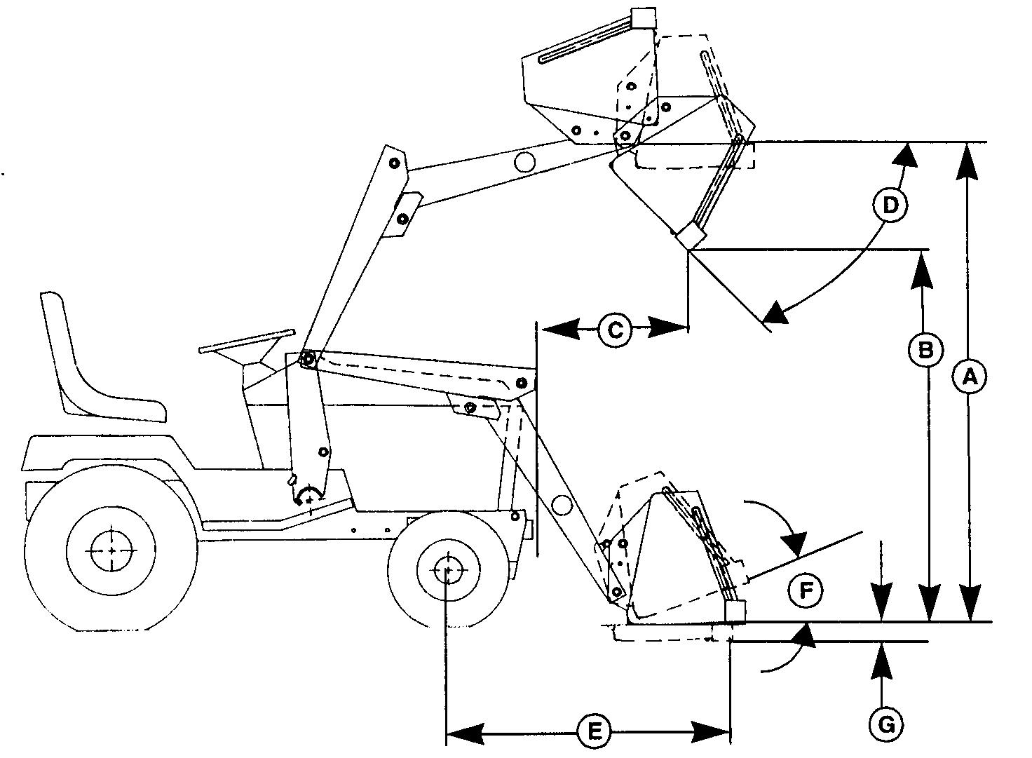
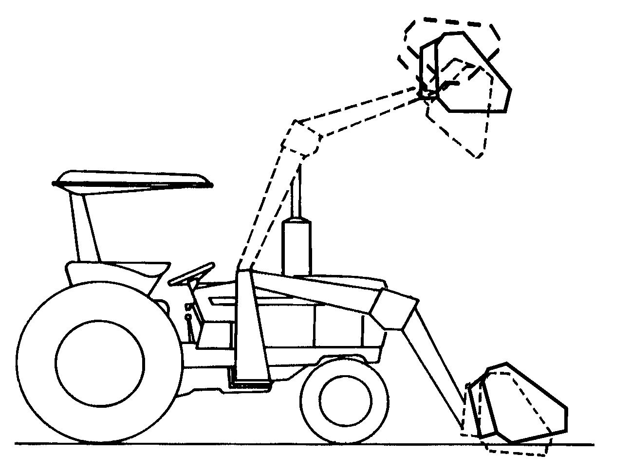
40, 44, 51, 52, 60, 67, 70, & 70A Loaders 365, 375, 380, 380A, & 390 Front Blades

30-Inch Hydraulic Tiller Hydraulic Dump MCS

This technical manual is written for an experieced technician and contains sections that are specifically for this product. It is a part of a total product support program.

The manual is organized so that all the information on a particular system is kept together. The order of grouping is as follows:

• Table of Contents

• Specifications

• Component Location

• System Schematic

• Theory of Operation

• Troubleshooting Chart

• Diagnostics

• Tests & Adjustments

• Repair

Note: Depending on the particular section or system being covered, not all of the above groups may be used

Each section will be identified with a symbol rather than a number. The groups and pages within a section will be consecutively numbered

All information, illustrations and specifications in this manual are based on the latest information available at the time of publication. The right is reserved to make changes at any time without notice

We appreciate your input on this manual. To help, there are postage paid post cards included at the back. If you find any errors or want to comment on the layout of the manual please fill out one of the cards and mail it back to us.

COPYRIGHT© 1995

Horicon, Wisconsin

All rights reserved Information

RECOGNIZE SAFETY INFORMATION

HANDLE FLUIDS SAFELY-AVOID FIRES

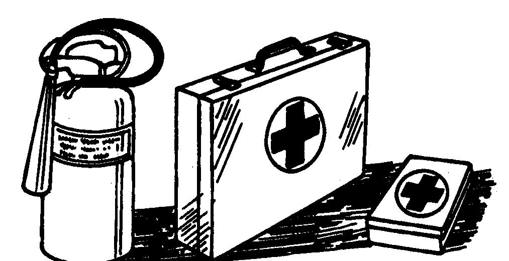
Be Prepared For Emergencies

This is the safety-alert symbol. When you see this symbol on your machine or in this manual, be alert to the potential for personal injury

Follow recommended precautions and safe servicing practices

Understand Signal Words

A signal word—DANGER, WARNING, or CAUTION— is used with the safety-alert symbol. DANGER identifies the most serious hazards

DANGER or WARNING safety signs are located near specific hazards. General precautions are listed on CAUTION safety signs. CAUTION also calls attention to safety messages in this manual

REPLACE SAFETY SIGNS

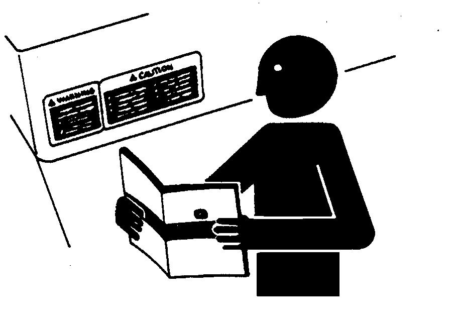
Replace missing or damaged safety signs. See the machine operator’s manual for correct safety sign placement

When you work around fuel, do not smoke or work near heaters or other fire hazards

Store flammable fluids away from fire hazards. Do not incinerate or puncture pressurized containers

Make sure machine is clean of trash, grease, and debris

Do not store oily rags; they can ignite and burn spontaneously

Be prepared if a fire starts

Keep a first aid kit and fire extinguisher handy

Keep emergency numbers for doctors, ambulance service, hospital, and fire department near your telephone

TS201
TS291
TS227

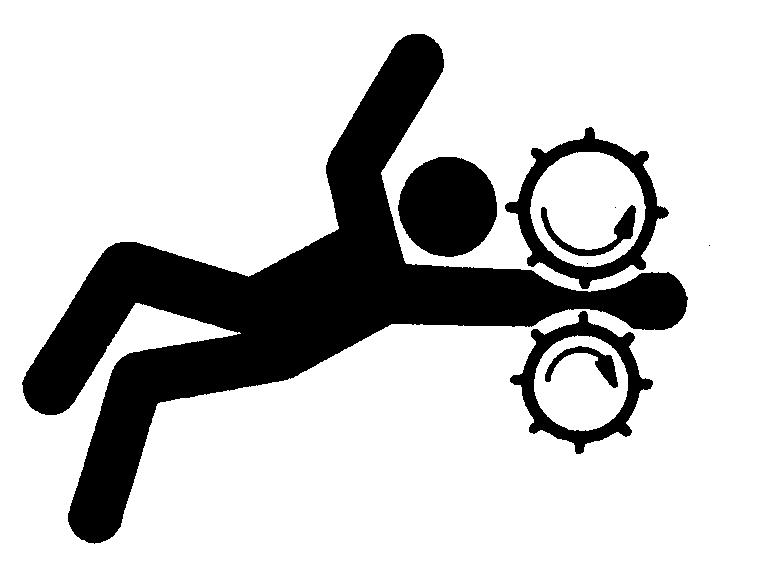
USE CARE AROUND HIGHPRESSURE FLUID LINES

Avoid High-pressure Fluids

USE SAFE SERVICE PROCEDURES

Wear Protective Clothing

Wear close fitting clothing and safety equipment appropriate to the job.

Prolonged exposure to loud noise can cause impairment or loss of hearing. Wear a suitable hearing protective device such as earmuffs or earplugs to protect against objectionable or uncomfortable loud noises.

Operating equipment safely requires the full attention of the operator. Do not wear radio or music headphones while operating machine

Escaping fluid under pressure can penetrate the skin causing serious injury.

Avoid injury from escaping fluid under pressure by stopping the engine and relieving pressure in the system before disconnecting or connecting hydraulic or other lines. Tighten all connections before applying pressure

Search for leaks with a piece of cardboard. Protect hands and body from high pressure fluids.

If an accident occurs, see a doctor immediately. Any fluid injected into the skin must be surgically removed within a few hours or gangrene may result. Doctors unfamiliar with this type of injury should reference a knowledgeable medical source. Such information is available from Deere & Company Medical Department in Moline, Illinois, U.S.A.

Avoid Heating Near Pressurized Fluid Lines

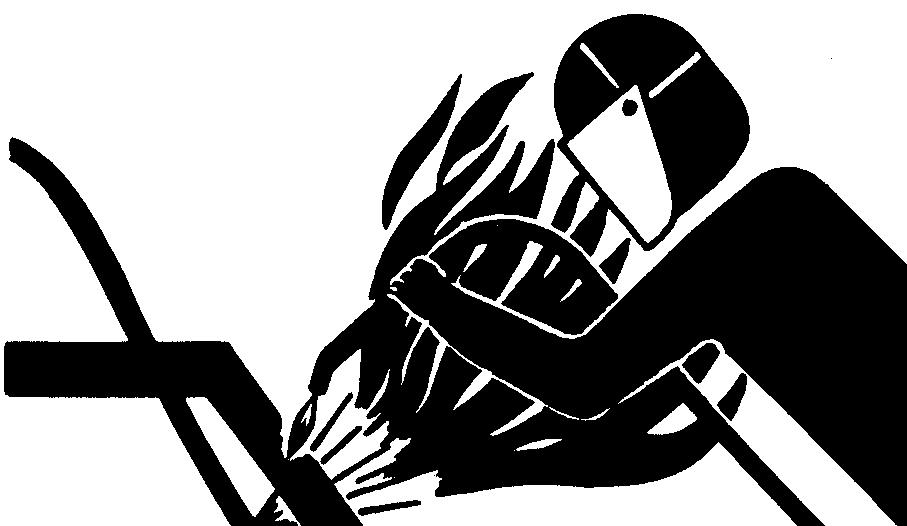
Flammable spray can be generated by heating near pressurized fluid lines, resulting in severe burns to yourself and bystanders. Do not heat by welding, soldering, or using a torch near pressurized fluid lines or other flammable materials. Pressurized lines can be accidentally cut when heat goes beyond the immediate flame area

Service Machines Safely

Tie long hair behind your head. Do not wear a necktie, scarf, loose clothing, or necklace when you work near machine tools or moving parts. If these items were to get caught, severe injury could result.

Remove rings and other jewelry to prevent electrical shorts and entanglement in moving parts

Use Proper Tools

Use tools appropriate to the work. Makeshift tools and procedures can create safety hazards. Use power tools only to loosen threaded parts and fasteners. For loosening and tightening hardware, use the correct size tools. DO NOT use U.S. measurement tools on metric fasteners. Avoid bodily injury caused by slipping wrenches. Use only service parts meeting John Deere specifications

TS953
TS228

Park Machine Safely

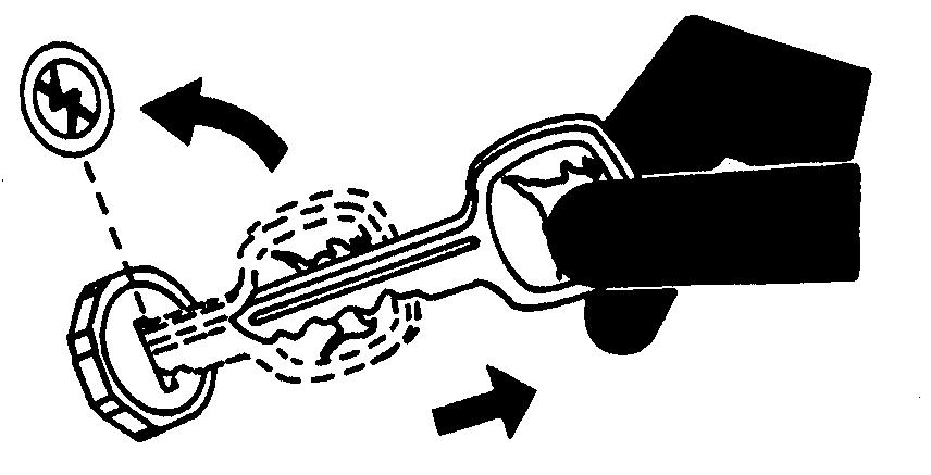
Before working on the machine:

1. Lower all equipment to the ground

2. Stop the engine and remove the key.

3. Disconnect the battery ground strap.

4. Hang a “DO NOT OPERATE” tag in operator station

Support Machine Properly And Use Proper Lifting Equipment

If you must work on a lifted machine or attachment, securely support the machine or attachment.

Do not support the machine on cinder blocks, hollow tiles, or props that may crumble under continuous load. Do not work under a machine that is supported solely by a jack. Follow recommended procedures in this manual

Lifting heavy components incorrectly can cause severe injury or machine damage. Follow recommended procedure for removal and installation of components in the manual

Work In Clean Area

Before starting a job:

1. Clean work area and machine

2. Make sure you have all necessary tools to do your job.

3. Have the right parts on hand.

4. Read all instructions thoroughly; do not attempt shortcuts

Using High Pressure Washers

Directing pressurized water at electronic/electrical components or connectors, bearings, hydraulic seals, fuel injection pumps or other sensitive parts and components may cause product malfunctions. Reduce pressure and spray at a 45 to 90 degree angle

Illuminate Work Area Safely

Illuminate your work area adequately but safely. Use a portable safety light for working inside or under the machine. Make sure the bulb is enclosed by a wire cage. The hot filament of an accidentally broken bulb can ignite spilled fuel or oil

Work In Ventilated Area

Engine exhaust fumes can cause sickness or death. If it is necessary to run an engine in an enclosed area, remove the exhaust fumes from the area with an exhaust pipe extension

If you do not have an exhaust pipe extension, open the doors and get outside air into the area

Remove Paint Before Welding Or Heating

Avoid potentially toxic fumes and dust. Hazardous fumes can be generated when paint is heated by welding, soldering, or using a torch. Do all work outside or in a well ventilated area. Dispose of paint and solvent properly. Remove paint before welding or heating: If you sand or grind paint, avoid breathing the dust. Wear an approved respirator. If you use solvent or paint stripper, remove stripper with soap and water before welding. Remove solvent or paint stripper containers and other flammable material from area. Allow fumes to disperse at least 15 minutes before welding or heating

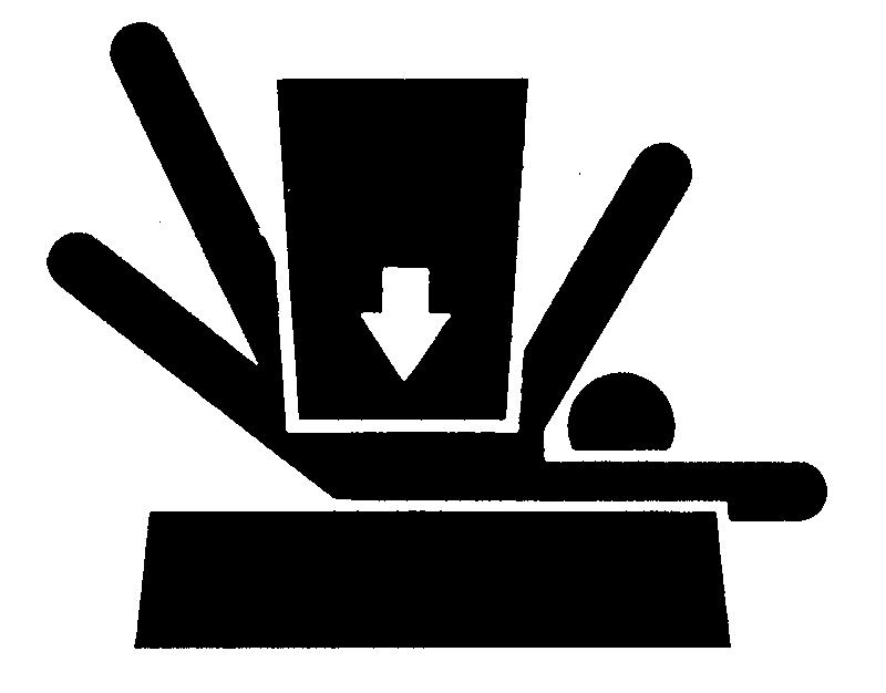
AVOID INJURY FROM ROTATING BLADES, AUGERS AND PTO SHAFTS

Dispose of Waste Properly

Improperly disposing of waste can threaten the environment and ecology. Potentially harmful waste used with John Deere equipment include such items as oil, fuel, coolant, brake fluid, filters, and batteries. Use leakproof containers when draining fluids. Do not use food or beverage containers that may mislead someone into drinking from them. Do not pour waste onto the ground, down a drain, or into any water source. Inquire on the proper way to recycle or dispose of waste from your local environmental or recycling center, or from your John Deere dealer

LIVE WITH SAFETY

Keep hands and feet away while machine is running. Shut off power to service, lubricate or remove mower blades, augers or PTO shafts

HANDLE CHEMICAL PRODUCTS SAFELY

Direct exposure to hazardous chemicals can cause serious injury. Potentially hazardous chemicals used with John Deere equipment include such items as lubricants, coolants, paints, and adhesives

A Material Safety Data Sheet (MSDS) provides specific details on chemical products: physical and health hazards, safety procedures, and emergency response techniques. Check the MSDS before you start any job using a hazardous chemical. That way you will know exactly what the risks are and how to do the job safely. Then follow procedures and recommended equipment.

Before returning machine to customer, make sure machine is functioning properly, especially the safety systems. Install all guards and shields

7, 8, 8A, 10, & 10A BACKHOES

HYDRAULIC SYSTEM REQUIREMENTS AND SPECIFICATIONS

Hydraulic Pump Flow Rates

650. . .

. 18.2 L/min, (4.8 gpm), 2600 RPM—Eng.

650 w/Power Steering 14.6 L/min (3.7 gpm), 2600 RPM—Eng

750 21.6 L/min (5.7 gpm), 2400 RPM—Eng

750 w/Power Steering 17.4 L/min (4.6 gpm), 2400 RPM—Eng

755 15.4 L/min (3.9 gpm), 3200 RPM—Eng

850 (9 cc) 23.5 L/min (6.2 gpm), 2600 RPM—Eng

850 (9 cc) w/Power Steering 16.7 L/min (4.4 gpm), 2600 RPM—Eng

850 (11 cc).

28.8 L/min (4.4 gpm), 2600 RPM—Eng. 850 (11 cc) w/Power Steering 22 L/min (5.8 gpm), 2600 RPM—Eng

855 15.4 L/min (3.9 gpm), 3200 RPM—Eng

950, 1050 (9 cc) w/Power Steering 14.8 L/min (3.9 gpm), 2400 RPM—Eng

950, 1050 (11 cc) 26.5 L/min (7.0 gpm), 2400 RPM—Eng 950, 1050 (11 cc) w/Power Steering

. 19.7 L/min (5.2 gpm), 2400 RPM—Eng. 5200, 5300, 5400 43.2 L/min (11.4 gpm), 2500 RPM—Eng 570 Skid-Steer Loader 27.2 L/min (7.2 gpm), 2500 RPM—Eng 575 Skid-Steer Loader .

30.3 L/min (8.0 gpm), 2800 RPM—Eng. 675 Skid-Steer Loader

53.0 L/min (14.0 gpm), 2800 RPM—Eng

BACKHOE HYDRAULIC SPECIFICATIONS

Main System Relief Valve Test Engine Speed.

Pressure

1500 RPM

7 Backhoe 11713 (10680 min.)kPa (117.3 [106.9 min.] bar) (1700 [1550 min.] psi)

8 & 8A Backhoe 14124.5 [13091.5 min.] kPa (141.5 [131.1 min.] bar) (2050 [1900 min.] psi) 10A Backhoe 15847 [14814 min.] kPa (158.7 [148.3 min.] bar) (2300 [2150 min.] psi)

Circuit Relief Valve Setting

Boom and Dipperstick

7 Backhoe 14469 ±689 kPa (79 ±5 bar) (2100 ±100 psi)

8, 8A, 10 and 10A Backhoe 19981 ±689.5 kPa (179.5 ±6.5 bar) (2600 ±100 psi)

Shim Sizes

7 and 8, 8A Backhoe 1.02 mm (0.04 in.), 0.51 mm (0.02 in.), (0.254 mm (0.01 in.)

Crossover Relief Valve Setting

Test Engine Speed 800 RPM

7, 8, and 8A Backhoe. . . . . . . . . . 7407—8440 kPa (74.2—84.5 bar) (1075—1225 psi) 10 and 10A Backhoe 10335—11369 kPa (103.5—113.9 bar) (1500—1650 psi)

Boom

Restrictor Orifice I.D

7 Backhoe 1.575 mm (0.062 in.)

8 and 8A Backhoe 1.88 mm (0.074 in.),

10 and 10A Backhoe

1.88 mm (0.074 in.)

Swing

Restrictor Orifice I.D. (2)

7 Backhoe

1.575 mm (0.062 in.)

8 and 8A Backhoe 1.19 mm (0.046 in.)

10 and 10A Backhoe

Stabilizer

Restrictor Orifice I.D. (2)

1.4 mm (0.055 in.)

7 Backhoe (after Nov. 1989) 1.575 mm (0.062 in.)

8 and 8A Backhoe (after April 1990) .

INTERNAL VALVE LEAKAGE

(Maximum acceptable limit)

1.88 mm (0.074 in.)

Stabilizer Circuit 12 ML/min (0.73 cu. in./min)

Lift Circuit (with relief and check)

LIFT CYLINDER DROP RATE

(Maximum acceptable limit from transport position)

. 22 ML/min (1.34 cu.in./min)

7 14.48 mm/min (.57 in./min)

8, 8A.

.9.15 mm/min (.36 in./min)

10, 10A 7.62 mm/min (.30 in./min)

STABILIZER CYLINDER DROP RATE

(Maximum acceptable limit from transport position)

7

.8.64 mm/min (.34 in./min)

8, 8A 5.85 mm/min (.23 in./min)

10, 10A.

STABILIZER CYLINDER RETRACT RATE

(Maximum acceptable limit from working position)

.5.85 mm/min (.23 in./min)

7 5.85 mm/min (.23 in./min)

8, 8A 3.81 mm/min (.15 in./min)

10, 10A 3.81 mm/min (.15 in./min)

7 BACKHOE FUNCTION TIMES

NOTE: All times in seconds

MODEL

*Arm extended, bucket in closed position, ground level to full boom extension

b With power steering

8 AND 8A BACKHOE FUNCTION TIMES—TRACTORS

NOTE: All times in seconds MODEL *Arm

8 AND 8A BACKHOE FUNCTION TIMES—SKID-STEER LOADERS

NOTE: All times in seconds

MODEL

*Arm extended, bucket in closed position, ground level to full boom extension

10 AND 10A BACKHOE FUNCTION TIMES

NOTE: All times in seconds

LOADERS

CAPACITY—44 Loader, 316, 318, 330, 420 and 430 Tractor

316, 318 & 330 420 & 430

Lift Capacity 180 kg (400 lb.) 225 kg (500 lb.)

Rated Breakout Capacity 260 kg (575 lb.)

1220 mm (48 in.) Bucket

1370 mm (54 in.) Bucket

CAPACITY—40 Loader, 415, 425, 445 and 455 Tractor (Two-Wheel Steer)

kg (725 lb.)

Lift Capacity at Full Height 98 kg (215 lb.) at 900 mm (36 in.) .

.159 kg (350 lb.)

Breakout (Boom) 226 kg (500 lb.)

Breakout (Bucket).

CAPACITY—60 Loader, 650, and 655 Tractor

.272 kg (600 lb.)

Lift Capacity at Full Height 273 kg (600 lb.) at 450 mm (18 in.) 385 kg (845 lb.) at 900 mm (36 in.) 335 kg (735 lb.)

Breakout (Boom)

. 4010 N (900 lb.)

Breakout (Bucket) 6660 N (1495 lb.)

CAPACITY—60 Loader, 670 Tractor

Lift Capacity at Full Height 297 kg (655 lb.) at 450 mm (18 in.) 385 kg (845 lb.) at 900 mm (36 in.) 335 kg (735 lb.)

Breakout (Boom) 4010 N (900 lb.)

Breakout (Bucket) 6660 N (1495 lb.)

CAPACITY—70, Loader, 750 Tractor

Lift Capacity at Full Height 318 kg (700 lb.) at 450 mm (18 in.) 540 kg (1190 lb.) at 900 mm (36 in.)

kg (735 lb.)

kg (1010 lb.) at 1800 mm (72 in.)

Breakout (Boom) 5790 N (1300 lb.)

Breakout (Bucket).

. 6995 N (1570 lb.)

CAPACITY—70, 70A Loader, 755, 770 and 855 Tractor

Lift Capacity at Full Height

kg (755 lb.) at 450 mm (18 in.)

kg (1190 lb.) at 900 mm (36 in.)

kg (1010 lb.) at 1800 mm (72 in.)

Breakout (Boom)

kg (735 lb.)

5790 N (1300 lb.)

Breakout (Bucket) 6995 N (1570 lb.)

CAPACITY—70A Loader, 955 Tractor

Lift Capacity at Full Height

.422 kg (930 lb.) at 450 mm (18 in.)

.659 kg (1450 lb.) at 900 mm (36 in.)

559 kg (1230 lb.) at 1800 mm (72 in.)

Breakout (Boom)

407 kg (895 lb.)

7060 N (1585 lb.)

Breakout (Bucket) 8530 N (1915 lb.)

DIMENSIONS—40 Loader, 415, 425, 445, 455 (Two-Wheel Steer)

Tractor Tire Size Specifications

Loader Dimensions

A—Maximum Lift Height (lowest point on bucket)

B—Maximum Clearance Under Fully Dumped Bucket

C—Reach With Fully Dumped Bucket 45°

D—Maximum Bucket Dump Angle

E—Reach With Bucket On Ground

F—Bucket Rollback Angle On Ground

G—Digging Depth Below Ground

Required Tractor Ballasting w/23 in. Tires

(42.5 in.)

(4

Minimum of 295 kg (650 lb.) rear ballast, 113 kg (250 lb.) on rear wheels w/26 in. Tires Minimum of 340 kg (750 lb.) rear ballast, 113 kg (250 lb.) on rear wheels

Hydraulic System

Pump, Reservoir, and Controls Tractor Rated Pressure 6890 kPa (1000 psi) Lift Cylinder Diameter 38 mm (1.5 in.) Bucket Cylinder Diameter.

44 mm (1.75 in.)

M78226

DIMENSIONS—44 LOADER

Loader Dimensions

316, 318, & 330 420 430

A—Maximum Lift Height 1816 mm (71.5 in.) 1854 mm (73 in.)

mm (73 in.) (lowest point on bucket)

B—Maximum Clearance

mm (52 in.) 1358 mm (53.5 in.)

mm (53.5 in.) (Fully Dumped Bucket)

C—Reach

mm (21 in.)

mm (22 in.)

mm (22 in.) (Fully Dumped Bucket 45°)

D—Maximum Bucket Dump Angle

E—Reach With Bucket On Ground 1117 mm (44 in.) 1130 mm (44.5 in.)

F—Bucket Rollback Angle

G—Digging Depth Below Ground

mm (4.5 in.)

mm (51.25 in.)

mm (4 in.)

NOTE: Operating dimensions vary with tractor size, and bucket used. Dimensions for the 44 Loader are given on the John Deere 318 Tractor with 6.50x16 front tires, 10.5x23 rear tires and a 1220 mm (48 in.) bucket. The John Deere 420 and 430 Tractors are equipped with 8.50x18 front tires, 12.00x26 rear tires and a 1220 mm (48 in.) bucket

Required Tractor Ballasting

34 kg (75 lb.) of rear wheel weights (total), Maximum liquid in rear tires, & 77 kg (170 lb.) on rear wheels (min.)

Hydraulic System

316, 318 & 330

& 430

Pump, Reservoir, and Controls Independent Independent Rated Pressure

mm (1.75 in.)

mm (1.75 in.)

mm (18.38 in.)

(1.75 in.)

(1.75 in.)

in.)

mm (14.5 in.)

M78226

DIMENSIONS—60, 70, 70A

MODEL

B—Clearance

Based On Tractor Tire Size:

CYCLE TIMES

NOTE: All times in seconds

MODEL

Cycle times are based on flow rates at S.C.V. and with power steering 1220 mm (48 in.) bucket size used

BUCKET STRUCK CAPACITY

48-Inch

0.17 mm3 (6.2 cu-ft.)

54-Inch 0.19 mm3 (7.0 cu-ft.)

60-Inch

INTERNAL VALVE LEAKAGE

(Maximum acceptable limit)

0.22 mm3 (7.8 cu-ft.)

655, 670, 770, 755, 855, and 955 12ML/min (0.73 cu. in.)

LIFT CYLINDER DROP RATE

(Maximum

from transport position)

BUCKET CYLINDER DROP RATE

FITTINGS

SERVICERECOMMENDATIONSFOR O-RING BOSS FITTINGS

STRAIGHT FITTING

1. Inspect O-ring boss seal for dirt or defects

2. Lubricate O-rings with petroleum jelly. Place electrical tape over threads to protect O-ring. Slide O-ring over tape and into O-ring groove of fitting. Remove tape

3. Tighten fitting to torque value shown on chart

ANGLE FITTING

1. Back-off lock nut (A) and back-up washer (B) completely to head-end (C) of fitting

2. Turn fitting into threaded boss until back-up washer contacts face of boss.

3. Turn fitting head-end counterclockwise to proper index (maximum of one turn).

4. Hold fitting head-end with a wrench and tighten locknut and back-up washer to proper torque value

NOTE: Do not allow hoses to twist when tightening fittings

TORQUE VALUE

NOTE: Torque tolerance is 10%

DOWNLOAD TECHNICAL MANUAL

M82649A
M82650A

Turn static files into dynamic content formats.

Create a flipbook
Issuu converts static files into: digital portfolios, online yearbooks, online catalogs, digital photo albums and more. Sign up and create your flipbook.