Introduction
Forward
Thismanual(CTM170)iswrittenforanexperienced technician.Essentialtoolsrequiredinperforming certainserviceworkareidentifiedinthismanualand arerecommendedforuse.
ThismanualcoversonlyLevel4ElectronicFuel SystemswiththeBoschVP44injectionpump.Itisone offivevolumeson4.5Land6.8Lengines.The followingfourcompanionmanualscoverthebase engineandmechanicalfuelsystemrepair,operation anddiagnostics:
• CTM104—BaseEngine
• CTM207—MechanicalFuelSystems
• CTM220—Level11ElectronicFuelSystemwith DensoHighPressureCommonRail
• CTM331—Level12electronicFuelSystemwith DE10Pump
Othermanualswillbeaddedinthefuturetoprovide additionalinformationonelectronicfuelsystemsas needed.
Livewithsafety:Readthesafetymessagesinthe introductionofthismanualandthecautionspresented throughoutthetextofthemanual.
Thisisthesafety-alertsymbol.Whenyouseethis symbolonthemachineorinthismanual,bealertto thepotentialforpersonalinjury.
Usethiscomponenttechnicalmanualinconjunction withthemachinetechnicalmanual.Anapplication listinginSection01,Group001identifies product-model/componenttype-modelrelationship.See themachinetechnicalmanualforinformationon
componentremovalandinstallation,andgaining accesstothecomponents.
Informationisorganizedinsectionsandgroupsforthe variouscomponentsrequiringserviceinstruction.At thebeginningofeachgrouparesummarylistingsofall applicableessentialtools,serviceequipmentandtools, othermaterialsneededtodothejob,servicepartskits, specifications,weartolerances,andtorquevalues.
Beforebeginningrepaironanengine,cleanthe engine.
ThismanualcontainsSIMetricunitsofmeasure followedimmediatelybytheU.S.customaryunitsof measure.Mosthardwareontheseenginesismetric sized.
Somecomponentsofthisenginemaybeserviced withoutremovingtheenginefromthemachine.Refer tothespecificmachinetechnicalmanualfor informationoncomponentsthatcanbeserviced withoutremovingtheenginefromthemachineandfor engineremovalandinstallationprocedures.
Readeachblockofmaterialcompletelybefore performingservicetocheckfordifferencesin proceduresorspecifications.Followonlythe proceduresthatapplytotheenginemodelnumberyou areworkingon.Ifonlyoneprocedureisgiven,that procedureappliestoalltheenginesinthemanual.
CALIFORNIAPROPOSITION65WARNING
Dieselengineexhaustandsomeofitsconstituentsare knowntotheStateofCaliforniatocausecancer,birth defectsandotherreproductiveharm.
DPSG,OUO1004,2760–19–17JUL01–1/1
SECTION01—General Group000—Safety Group001—EngineIdentification Group002—Fuels
SECTION02—RepairandAdjustments Group090—ElectronicFuelSystemRepairand Adjustments
Group110—ElectricalEngineControlRepairand Adjustment
SECTION03—TheoryofOperation Group130—ElectronicFuelSystemOperation Group140—ElectronicControlSystemOperation
SECTION04—Diagnostics
Group150—ObservableDiagnosticsandTests Group160—TroubleCodeDiagnosticsandTests
SECTION05—ToolsandOtherMaterials Group170—ElectronicFuel/ControlSystemRepair ToolsandOtherMaterials Group180—DiagnosticServiceTools
SECTION06—Specifications Group200—RepairSpecifications Group210—DiagnosticSpecifications
Allinformation,illustrationsandspecificationsinthismanualarebasedon thelatestinformationavailableatthetimeofpublication.Therightis reservedtomakechangesatanytimewithoutnotice.
Group000—Safety
Group001—EngineIdentification
EngineModelDesignation
EngineSerialNumberPlateInformation 01-001-2
OEMEngineOptionCodeLabel 01-001-3
Group002—Fuels
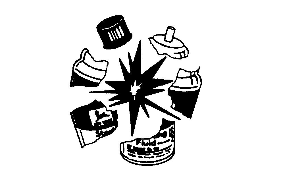
HandleFluidsSafely—AvoidFires
Whenyouworkaroundfuel,donotsmokeorworknear heatersorotherfirehazards.
Storeflammablefluidsawayfromfirehazards.Donot incinerateorpuncturepressurizedcontainers.
Makesuremachineiscleanoftrash,grease,anddebris.
Donotstoreoilyrags;theycanigniteandburn spontaneously.
HandleStartingFluidSafely
Startingfluidishighlyflammable.
Keepallsparksandflameawaywhenusingit.Keep startingfluidawayfrombatteriesandcables.
Topreventaccidentaldischargewhenstoringthe pressurizedcan,keepthecaponthecontainer,andstore inacool,protectedlocation.
Donotincinerateorpunctureastartingfluidcontainer.
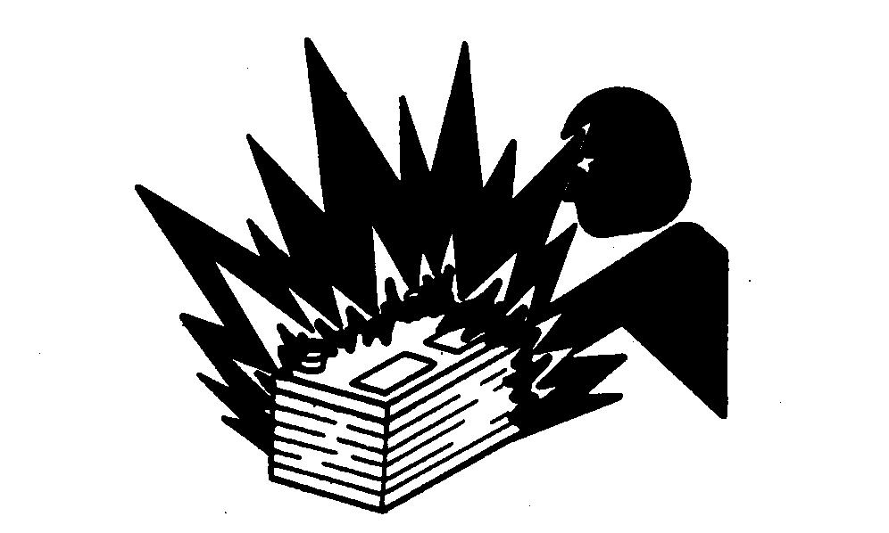
ServiceCoolingSystemSafely
Explosivereleaseoffluidsfrompressurizedcooling systemcancauseseriousburns.
Shutoffengine.Onlyremovefillercapwhencoolenough totouchwithbarehands.Slowlyloosencaptofirststop torelievepressurebeforeremovingcompletely.
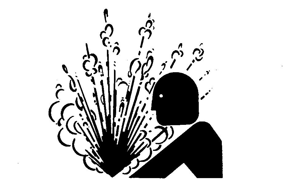
PreventBatteryExplosions
Keepsparks,lightedmatches,andopenflameawayfrom thetopofbattery.Batterygascanexplode.
Nevercheckbatterychargebyplacingametalobject acrosstheposts.Useavolt-meterorhydrometer.
Donotchargeafrozenbattery;itmayexplode.Warm batteryto16°C(60°F).
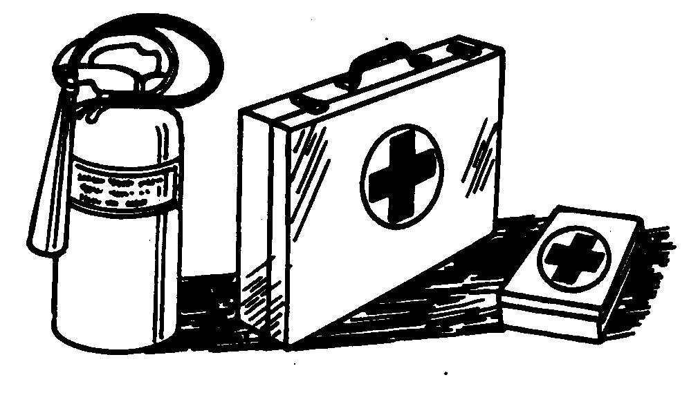
PrepareforEmergencies
Bepreparedifafirestarts.
Keepafirstaidkitandfireextinguisherhandy.
Keepemergencynumbersfordoctors,ambulanceservice, hospital,andfiredepartmentnearyourtelephone.
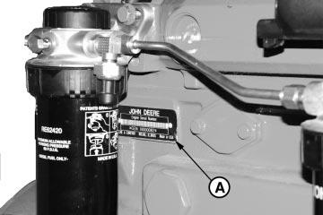
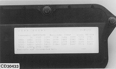
EngineSerialNumberPlateInformation
IMPORTANT:Theengineserialnumberplate(A)can beeasilydestroyed.Before“hottank” cleaningtheblock,removetheplate.
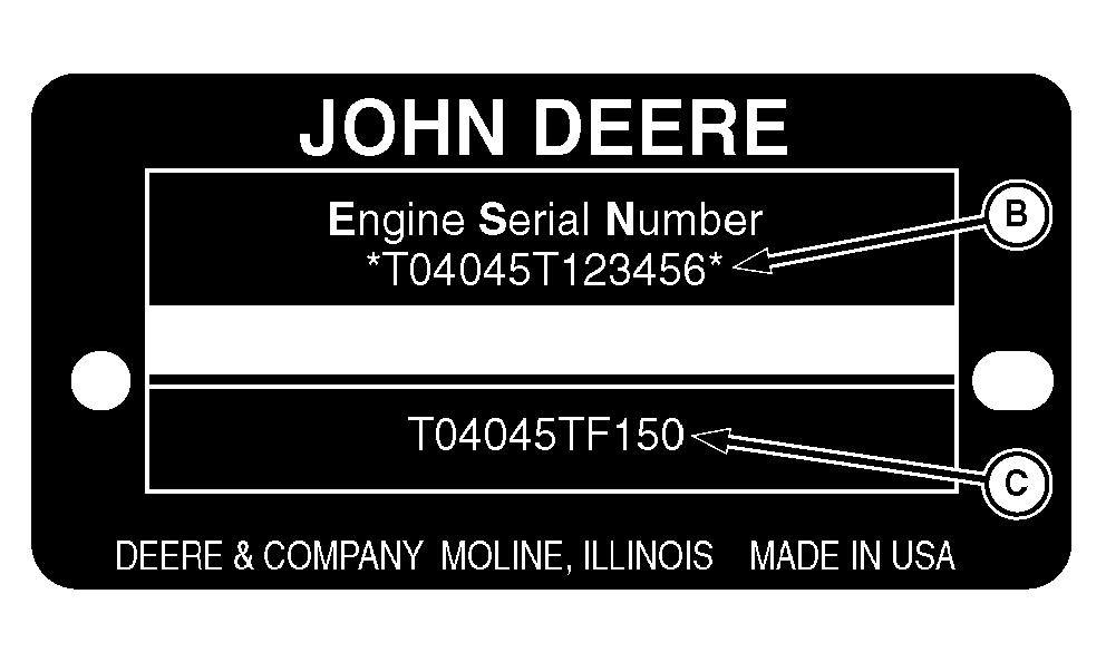
EngineSerialNumber(B)
Eachenginehasa13-digitJohnDeereengineserial numberidentifyingtheproducingfactory,enginemodel designation,anda6-digitsequentialnumber.The followingisanexample:
T04045T000000
T0...........................Factoryproducingengine 4045T.....................Enginemodeldesignation 000000...................Sequentialserialnumber FactoryCode(EngineManufacturer)
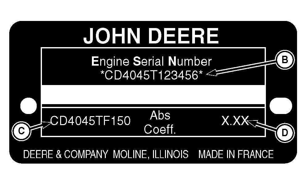
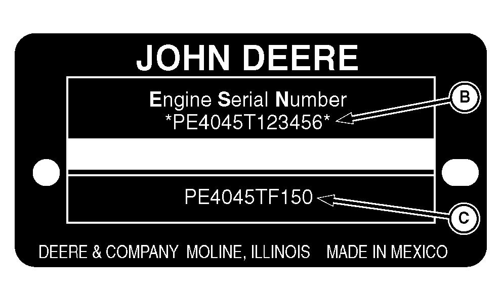
T0...........................Dubuque,Iowa CD..........................Saran,France PE..........................Torreon,Mexico EngineModelDesignation 4045T.....................Definitionexplainedpreviously.(SeeENGINE MODELDESIGNATIONearlierinthisgroup. SequentialNumber 000000...................6-digitsequentialserialnumber
EngineApplicationData(C)
Thesecondlineofinformationontheserialnumberplate identifiestheengine/machineorOEMrelationship.See ENGINEAPPLICATIONCHARTlaterinthisgroup.
CoefficientofAbsorption(D)—(Saran-BuiltEngines Only)
ThesecondlineofinformationonSaranserialnumber platealsocontainsthecoefficientofabsorptionvaluefor smokeemissions.
A—EngineSerialNumberPlate
B—EngineSerialNumber
C—EngineApplicationData
D—CoefficientofAbsorption(SaranEnginesOnly)
EngineIdentification
Tier1vs.Tier2
Thefueltransferpumpislocatedonthefinalfuelfilter headeronTier1applicationsandprimaryfuelfilteron Tier2applications.SomeTier2applicationsusearemote mountedfueltransferpump.FormoreinformationonTier 1vs.Tier2applications,seeENGINEAPPLICATION CHARTinGroup001earlierinthismanual.Thetransfer pumpiselectricallycontrolledbytheElectronicControl Unit(ECU).
AllTier1enginesareequippedwithafuelpressure sensoronthefinalfuelfilter.SomeTier2enginesusea fuelpressuresensorandsomedonot.
Tier1enginesmaybeequippedwithaprimaryfuel filter/waterseparator.AllTier2engineswillhavebotha primaryandfinalfuelfilter.
Tier1enginesmaybeequippedwitheithera30micron or150micronprimaryfilter.AllTier2engineshavea30 micronprimaryfilter.
Allenginesareequippedwitharoundfinalfuelfilter.
Allenginesuse9.5mmpencil-typenozzles.
Fuelsystemoptionsincludefuelheaterandwater separatorbowl.
IMPORTANT:TheBoschVP44InjectionPumpis electronicallycontrolled.Allconnectors onthepumpandtheenginecontrol unit(ECU)mustbedisconnectedbefore anyweldingisaccomplishedonthe engine,ordamagetotheelectrical systemislikelytooccur.
Tier2-FinalFuelfilter
Tier2-PrimaryFuelFilter
LubricantsandCoolant
NOTE:Forinformationonlubricantsandcoolants,refer toSection01,Group002ofCTM104Base EngineManualforinformationonlubricantsand coolants.
DieselFuel-Tier1
NOTE:ForinformationonTier1vs.Tier2 applications,seeENGINEAPPLICATION CHARTinGroup001earlierinthismanual.
Consultyourlocalfueldistributorforpropertiesofthe dieselfuelavailableinyourarea.
Ingeneral,dieselfuelsareblendedtosatisfythelow temperaturerequirementsofthegeographicalareain whichtheyaremarketed.
DieselfuelsspecifiedtoEN590orASTMD975are recommended.
Inallcases,thefuelshallmeetthefollowing properties:
• CetaneNumberof40minimum. Cetanenumber greaterthan50ispreferred,especiallyfor temperaturesbelow—20°C(—4°F)orelevations above1500m(5000ft).
• ColdFilterPluggingPoint(CFPP) belowthe expectedlowtemperatureORCloudPointatleast 5°C(9°F)belowtheexpectedlowtemperature.
• FuelLubricity shouldpassaminimumof3100 gramloadlevelasmeasuredbytheBOCLEscuffing test.
• SulfurContent
–Sulfurcontentshouldnotexceed0.5%.Sulfur contentlessthan0.05%ispreferred.
–Ifdieselfuelwithsulfurcontentgreaterthan0.5% isused,reducetheserviceintervalforengineoil andfilterby50%.
–DONOTusedieselfuelwithsulfurcontent greaterthan1.0%.
Bio-dieselfuelswithpropertiesmeetingDIN51606or equivalentspecificationmaybeused.
DONOTmixusedengineoiloranyothertypeof lubricantwithdieselfuel.
DieselFuel-Tier2
NOTE:ForinformationonTier1vs.Tier2 applications,seeENGINEAPPLICATION CHARTinGroup001earlierinthismanual.
Consultyourlocalfueldistributorforpropertiesofthe dieselfuelavailableinyourarea.
Ingeneral,dieselfuelsareblendedtosatisfythelow temperaturerequirementsofthegeographicalareain whichtheyaremarketed.
DieselfuelsspecifiedtoEN590orASTMD975are recommended.
Requiredfuelproperties
Inallcases,thefuelmustmeetthefollowing properties:
Cetanenumberof45minimum. Cetanenumber greaterthan50ispreferred,especiallyfor temperaturesbelow-20°C(-4°F)orelevationsabove 1500m(5000ft).
ColdFilterPluggingPoint (CFPP)belowthe expectedlowtemperatureOR CloudPoint atleast 5°C(9°F)belowtheexpectedlowtemperature.
Fuellubricity shouldpassaminimumloadlevelof 3100gramsasmeasuredbyASTMD6078or, maximumscardiameterof0.45mmasmeasuredby ASTMD6079.
Sulfurcontent:
• Dieselfuelqualityandfuelsulfurcontentmust complywithallexistingregulationsfortheareain whichtheengineoperates.
• Sulfurcontentlessthan0.05%(500ppm)is preferred.
• Ifdieselfuelwithsulfurcontentgreaterthan0.05% (500ppm)isused,crankcaseoilserviceintervals maybeaffected.(SeerecommendationforDiesel EngineOil.)
• DONOTusedieselfuelwithsulfurcontentgreater than1.0%.
IMPORTANT:DONOTmixusedengineoilorany othertypeoflubricatingoilwith dieselfuel.
RG41221,0000085–19–23OCT02–1/1
Bio-DieselFuel
Consultyourlocalfueldistributorforpropertiesofthe bio-dieselfuelavailableinyourarea.
Bio-dieselfuelsmaybeusedONLYifthebio-diesel fuelpropertiesmeetthelatesteditionofASTMPS121, DIN51606orequivalentspecification.
Ithasbeenfoundthatbio-dieselfuelsmayimprove lubricityinconcentrationsuptoa5%blendin petroleumdieselfuel.
Whenusingablendofbio-dieselfuel,theengineoil levelmustbecheckeddailywhentheairtemperature is-10°C(14°F)orlower.Iftheoilbecomesdilutedwith fuel,shortenoilchangeintervalsaccordingly.
IMPORTANT:RawpressedvegetableoilsareNOT acceptableforuseforfuelinany concentrationinJohnDeere engines.
Theseoilsdonotburncompletely, andwillcauseenginefailureby leavingdepositsoninjectorsandin thecombustionchamber.
Amajorenvironmentalbenefitofbio-dieselfuelisits abilitytobiodegrade.Thismakesproperstorageand handlingofbio-dieselfuelespeciallyimportant.Areas ofconcerninclude:
• Qualityofnewfuel
• Watercontentofthefuel
• Problemsduetoagingofthefuel
Potentialproblemsresultingfromdeficienciesinthe aboveareaswhenusingbio-dieselfuelin concentrationsabove5%mayleadtothefollowing symptoms:
• Powerlossanddeteriorationofperformance
• Fuelleakage
• Corrosionoffuelinjectionequipment
• Cokedand/orblockedinjectornozzles,resultingin enginemisfire
• Filterplugging
• Lacqueringand/orseizureofinternalcomponents
• Sludgeandsediments
• Reducedservicelifeofenginecomponents
RG41183,0000046–19–15NOV01–1/1
DieselscanFuelAnalysis
DIESELSCAN isaJohnDeerefuelsamplingprogramto helpyoumonitorthequalityofyourfuelsource.Itverifies fueltype,cleanliness,watercontent,suitabilityforcold weatheroperation,andiffueliswithinASTM specifications.CheckwithyourJohnDeeredealerfor availabilityofDIESELSCANkits.
DIESELSCANisatrademarkofDeere&Company
DX,FUEL6–19–06DEC00–1/1
LubricityofDieselFuel
Dieselfuelmusthaveadequatelubricitytoensure properoperationanddurabilityoffuelinjectionsystem components.
DieselfuelsforhighwayuseintheUnitedStates, Canada,andtheEuropeanUnionrequiresulfur contentlessthan0.05%.
Experienceshowsthatsomelowsulfurdieselfuels mayhaveinadequatelubricityandtheirusemay reduceperformanceinfuelinjectionsystemsdueto inadequatelubricationofinjectionpumpcomponents. Thelowerconcentrationofaromaticcompoundsin thesefuelsalsoadverselyaffectsinjectionpumpseals andmayresultinleaks.
Useoflowlubricitydieselfuelsmayalsocause acceleratedwear,injectionnozzleerosionorcorrosion, enginespeedinstability,hardstarting,lowpower,and enginesmoke.
Fuellubricityshouldpassaminimumof3100gram loadlevelasmeasuredbytheBOCLEscuffingtest.
ASTMD975andEN590specificationsdonotrequire fuelstopassafuellubricitytest.
Iffuelofloworunknownlubricityisused,addJohn DeerePREMIUMDIESELFUELCONDITIONER(or equivalent)atthespecifiedconcentration.
DX,FUEL5–19–17FEB99–1/1
RemoveandInstallElectronicFuel TransferPump-RemoteMount 02-090-12
ServiceInjectionPumpOverflowValve 02-090-13
BoschVP44InjectionPumpStaticTiming...02-090-14
RemoveBoschVP44FuelInjection Pump
02-090-16
RepairBoschVP44FuelInjectionPump .... 02-090-18
InstallBoschVP44FuelInjectionPump .... 02-090-19
RemoveFuelInjectionNozzles ........... 02-090-22
CleanFuelInjectionNozzleBore 02-090-24
CleanFuelInjectionNozzles 02-090-24
TestFuelInjectionNozzles 02-090-25
DisassembleFuelInjectionNozzles 02-090-30
InspectandCleanFuelInjectionNozzle Body 02-090-33
InspectandCleanValveandValveSeat...02-090-34
InspectValveAdjustingMechanism 02-090-36
AssembleFuelInjectionNozzles .......... 02-090-37
AdjustFuelInjectionNozzles ............ 02-090-38
InstallSealsonFuelInjectionNozzle 02-090-41
InstallFuelInjectionNozzles 02-090-42
Group110—ElectricalEngineControlRepairand Adjustment
EngineControlUnit(ECU) 02-110-1
RemoveandInstallEngineCoolant
02-110-2
ReplaceFuelPressureSensor 02-110-3
ReplacePumpPositionSensor 02-110-4
ReplaceCrankshaftPositionSensor 02-110-4
RemoveandInstallOilPressureSensor ..... 02-110-5
FuelSystem—GeneralInformation
Forstaticlock-pintimingoftheBoschVP44Injection Pump,seeBOSCHVP44INJECTIONPUMPSTATIC TIMINGinthisGroup.
Thefueltransferpumpislocatedonthefinalfuelfilter headeronTier1applicationsandprimaryfuelfilter,or remotemountedonTier2applications.Formore informationonTier1vs.Tier2applications,see ENGINEAPPLICATIONCHARTinGroup001earlier inthismanual.Thetransferpumpiselectrically controlledbytheElectronicControlUnit(ECU).
Tier1enginesmaybeequippedwithaprimaryfuel filter/waterseparator.AllTier2engineswillhaveboth aprimaryandfinalfuelfilter.
Allenginesareequippedwitharoundfinalfuelfilter.
Allenginesuse9.5mmpencil-typenozzles.
Fuelsystemoptionsincludefuelheaterandwater separatorbowl.
IMPORTANT:TheBoschVP44InjectionPumpis electronicallycontrolled.All connectorsonthepumpandthe enginecontrolunit(ECU)mustbe disconnectedbeforeanyweldingis accomplishedontheengine,or damagetotheelectricalsystemis likelytooccur.
RelieveFuelSystemPressure
CAUTION:Escapingdieselfuelunderpressure canhavesufficientforcetopenetratetheskin, causingseriousinjury.Beforedisconnecting lines,besuretorelievepressure.Before applyingpressuretothesystem,besureALL connectionsaretightandlines,pipesand hosesarenotdamaged.Keephandsandbody awayfrompinholesandnozzleswhicheject fluidunderpressure.Useapieceofcardboard orwood,ratherthanhands,tosearchfor suspectedleaks.
IfANYfluidisinjectedintotheskin,itmustbe surgicallyremovedwithinafewhoursbya doctorfamiliarwiththistypeofinjuryor gangrenemayresult.Doctorsunfamiliarwith thistypeofinjurymaycalltheDeere& CompanyMedicalDepartmentinMoline,Illinois, orotherknowledgeablemedicalsource.
Anytimethefuelsystemhasbeenopenedupforservice (linesdisconnectedorfiltersremoved),itwillbenecessary tobleedairfromthesystem.SeeBLEEDTHEFUEL SYSTEMinGroup150laterinthismanual.
RG,35,JW7625–19–20NOV97–1/1
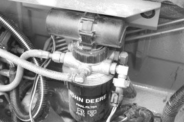
RemoveandInstallPrimaryFuelFilter/Water SeparatorBase-Tier2
NOTE:ForinformationonTier1vs.Tier2applications, seeENGINEAPPLICATIONCHARTinGroup 001earlierinthismanual.
Theprimaryfuelfiltermaybeequippedwithawater separatorbowl.
Theelectronicfueltransferpumpismountedontopofthe filterhead.
1.Thoroughlycleanprimaryfuelfilter/waterseparator assemblyandsurroundingareatokeepfromgetting dirtanddebrisintofuelsystem.
2.Connectafuellinetofilterdrain(ifequipped)on bottomoffilteranddrainallfuelfromthesystem.
3.Removeprimaryfuelfilterelement.
NOTE:Fuellinesmaybeconnectedtodifferentinletand outletportsdependingonengineapplication.
4.Disconnectfuellinesfromfuelinlet(C)andfueloutlet (D).
5.Disconnectfueltransferpumpconnector(F).
6.Removefilterbasecapscrews(B)andprimaryfuel filterbase.
NOTE:Mountingbracketdoesnotneedtoberemoved.
7.Replacepartsasnecessary.
8.Ifremoved,installmountingbracketonengine.Install filterbaseonmountingbracket.Tightencapscrewsto specification.
PrimaryFuelFilterMounting
Specification
Bracket-to-CylinderHeadCap
Screws—Torque74N•m(54.5lb-ft)
PrimaryFuelFilter
Base-to-BracketCapScrews— Torque60N•m(44lb-ft)
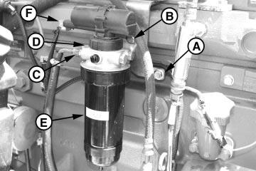
PrimaryFuelFilter-Tier2
A—FilterBrackettoEngineMountingCapScrews B—FilterBasetoBracketMountingCapScrews C—FuelInletLine(FromFuelTank) D—FuelOutlet(ToFinalFuelFilter) E—PrimaryFuelFilter F—FuelTransferPumpConnector
9.Installwaterseparatorandprimaryfuelfilterelement. SeeREPLACEFINALFUELFILTERELEMENTlater inthisGroup.
10.Connectfuellinestofuelinlet(C)andfueloutlet(D) andtightentospecification.
Specification
PrimaryFuelFilterInletLine—
Torque30N•m(22lb-ft)
PrimaryFuelFilterOutletLine—
Torque30N•m(22lb-ft)
11.Reconnectfueltransferpumpelectricalconnector.
12.Bleedthefuelsystem.SeeBLEEDTHEFUEL SYSTEMinGroup150laterinthismanual.
RG41221,00000FB–19–17OCT02–2/2
RemoveandInstallFinalFuelFilter/Water SeparatorBase-Tier1
NOTE:ForinformationonTier1vs.Tier2applications, seeENGINEAPPLICATIONCHARTinGroup 001earlierinthismanual.
Finalfuelfiltermaybeequippedwithawaterseparator bowl.
Theelectronicfueltransferpumpismountedontopofthe filterheader.
1.Thoroughlycleanfuelfilter/waterseparatorassembly andsurroundingareatokeepfromgettingdirtand debrisintofuelsystem.
2.Connectafuellinetofilterdrainonbottomoffilterand drainallfuelfromsystem.
3.Removefinalfuelfilterelement.SeeREPLACEFINAL FUELFILTERELEMENT,laterinthisGroup.
NOTE:Fuellinesmaybeconnectedtodifferentfilterinlet andoutletportsdependingonengineapplication.
4.Disconnectfuellinesfromfuelinlet(B),overflowvalve (E),andfueloutlet(F).
5.Disconnectfueltransferpumpconnector(G)andfuel pressuresensorconnector(C)(bothshown disconnected).
6.Removecapscrews(A)andfinalfuelfilterbase.
NOTE:Mountingbracketdoesnotneedtoberemoved.
7.Replacepartsasnecessary.
8.Ifremoved,installfiltermountingbracketonengine. Installfilterbaseonmountingbracket.Tightencap screwstospecifications.
Specification
FinalFuelFilterMounting
Bracket-to-ExhaustManifold— Torque70N•m(52lb-ft)
FinalFuelFilterBase-to-Bracket CapScrews—Torque70N•m(52lb-ft)
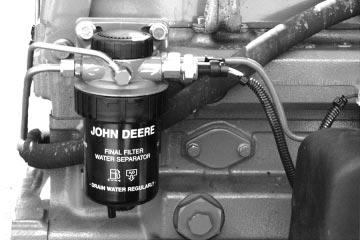
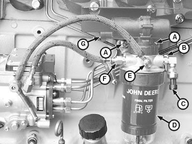
FinalFuelFilter-Tier1
A—FilterBaseMountingCapScrews
B—FuelInletLine(FromPrefilter)
C—FuelPressureSensorConnector
D—FinalFuelFilter
E—FuelOverflowLine(ToInjectionPump OverflowValve)
F—FuelOutletLine(ToInjectionPumpInlet)
G—FuelTransferPumpConnector
9.Installwaterseparatorandfuelfilterelement.See REPLACEFINALFUELFILTERELEMENTlaterinthis Group.
10.Connectfuellinestofuelinlet(B),overflowvalve(E), andfueloutlet(F)andtightentospecification.
FinalFuelFilterInletLine—
Specification
Torque30N•m(22lb-ft)
FinalFuelFilterOutletLine—
Torque30N•m(22lb-ft)
11.Reconnectfueltransferpumpandfuelpressure sensorelectricalconnectors.
12.Bleedthefuelsystem.SeeBLEEDTHEFUEL SYSTEMinGroup150laterinthismanual.
RG41221,0000105–19–17OCT02–2/2
RemoveandInstallFinalFuelFilter/Water SeparatorBase-Tier2
NOTE:ForinformationonTier1vs.Tier2applications, seeENGINEAPPLICATIONCHARTinGroup 001earlierinthismanual.
Finalfuelfiltermaybeequippedwithawaterseparator bowl.
1.Thoroughlycleanfuelfilter/waterseparatorassembly andsurroundingareatokeepfromgettingdirtand debrisintofuelsystem.
2.Connectafuellinetofilterdrainanddrainallfuelfrom system.
3.Removefinalfuelfilterelement.SeeREPLACEFINAL FUELFILTERELEMENTlaterinthisGroup.
NOTE:Fuellinesmaybeconnectedtodifferentfilterinlet andoutletportsdependingonengineapplication.
4.Disconnectfuellinesfromfuelinlet(B),overflowvalve (E),andfueloutlet(F).
5.Disconnectfuelpressuresensorconnector(C).
6.Removecapscrews(A)andfinalfuelfilterbase. Removefinalfilter.
7.Replacepartsasnecessary.
8.Installfilterbaseonenginecylinderhead.Tightencap screwstospecifications.
Specification
FinalFuelFilterBase-to-Cylinder Head—Torque70N•m(52lb-ft)
9.Installwaterseparatorandfuelfilterelement.See REPLACEFINALFUELFILTERELEMENTlaterinthis Group.
10.Connectfuellinestofuelinlet(B),overflowvalve(E), andfueloutlet(F)andtightentospecification.
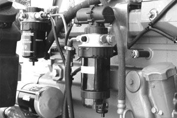
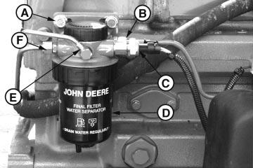
FinalFuelFilter-Tier2
A—FilterBaseMountingCapScrews
B—FuelInletLine(FromPrefilter)
C—FuelPressureSensorConnector
D—FinalFuelFilter
E—FuelOverflowLine(ToInjectionPump OverflowValve)
F—FuelOutletLine(ToInjectionPumpInlet)
FinalFuelFilterInletLine—
Specification
Torque30N•m(22lb-ft)
FinalFuelFilterOutletLine—
Torque30N•m(22lb-ft)
11.Reconnectthefuelpressureelectricalconnector.
12.Bleedthefuelsystem.SeeBLEEDTHEFUEL SYSTEMinGroup150laterinthismanual.
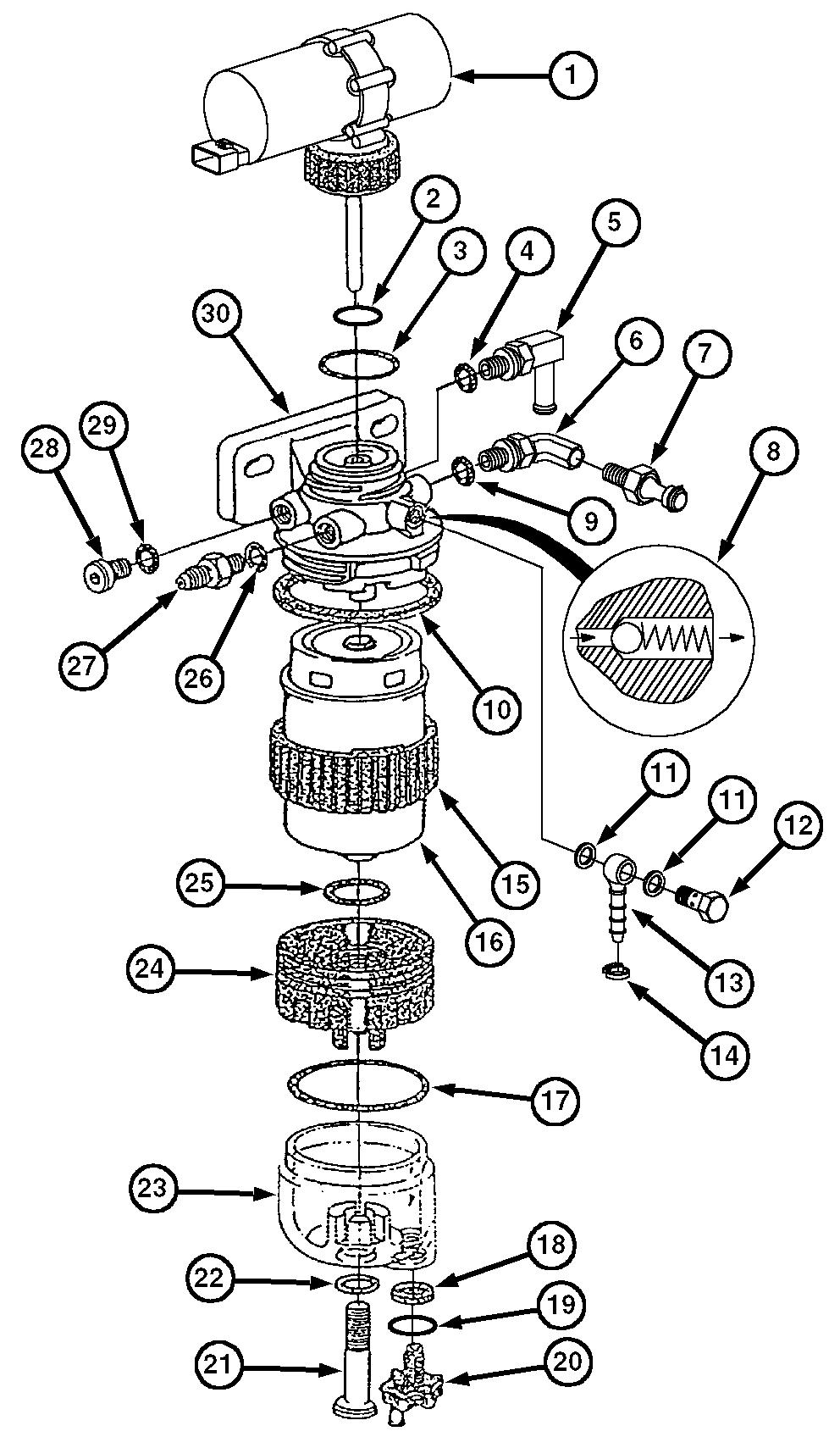
FinalFuelFilterAssembly-Tier1
NOTE:ForinformationonTier1vs.Tier2applications, seeENGINEAPPLICATIONCHARTinGroup 001earlierinthismanual.
1—FuelTransferPump 2—O-Ring 3—O-Ring 4—O-Ring 5—Fitting 6—Fitting 7—FuelPressureSensor 8—AirBleedSpringandBall(Non-Serviceable) 9—O-Ring 10—DustSeal 11—CopperWasher 12—BanjoBolt 13—BanjoFitting 14—HoseClamp 15—RetainingRing 16—Filter 17—O-Ring 18—Gasket 19—O-Ring 20—DrainAdapter 21—Screw 22—O-Ring 23—WaterSeparatorBowl 24—Adapter 25—O-Ring 26—O-Ring 27—Fitting 28—Plug1 29—O-Ring 30—FilterBase
RG41221,00000FC–19–17OCT02–2/2
1Anoptionalfuelheaterisavailableforinstallationinthisbore.
RG41221,0000106–19–09MAY01–1/1
FinalFuelFilter-Tier1
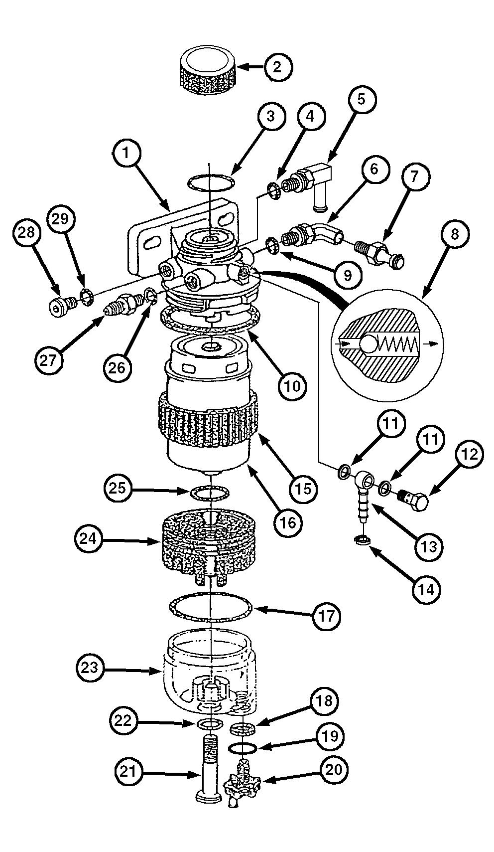
FinalFuelFilterAssembly-Tier2
NOTE:ForinformationonTier1vs.Tier2applications, seeENGINEAPPLICATIONCHARTinGroup 001earlierinthismanual.
1—FilterBase 2—FinalFuelFilterCover 3—O-Ring 4—O-Ring 5—Fitting 6—Fitting 7—FuelPressureSensor 8—AirBleedSpringandBall(Non-Serviceable) 9—O-Ring 10—DustSeal 11—CopperWasher 12—BanjoBolt 13—BanjoFitting 14—HoseClamp 15—RetainingRing 16—Filter 17—O-Ring 18—Gasket 19—O-Ring 20—DrainAdapter 21—Screw 22—O-Ring 23—WaterSeparatorBowl 24—Adapter 25—O-Ring 26—O-Ring 27—Fitting 28—Plug1 29—O-Ring
FinalFuelFilter-Tier2
1Anoptionalfuelheaterisavailableforinstallationinthisbore.
EngineControlUnitCylinderMisfireTest 04-160-22
ExcavatorTorqueCurveChange Repair 02-110-1
TheoryofOperation............... 03-140-21Test ......................... 04-160-26
Coolant ............................. 01-002-1
TractorTorqueCurveChangeTest...04-160-27
CoolanttemperaturesensorDiagnosticTools 05-180-1
Operation 03-140-8
DiagnosticTroubleCodes
CrankPositionSensorBlinkingCodes 04-160-15 DiagnosticTroubleCodes(DTCs) MeasuringSpeed 03-140-16
CruiseControlOperation 03-140-23
Replace 02-110-4ActiveEngineServiceCodes, Viewing 04-160-13
CylinderCutoutTestActivevs.Inactive 03-140-26 ClearingStoredCodes 03-140-26
EngineTestInstructions 04-160-25
CylinderMisfireTestDiagnosticProcedure ............... 04-160-56
EngineTestInstructions ............. 04-160-22
DisplayFormat .................... 03-140-26
ObservableInstructions .............. 04-150-76ListofSPN/FMI.................... 04-160-52
Listof2-Digit 04-160-54 Listingof 04-160-52 SPN/FMI 04-160-51
DataParameterDescription DiagnosticScanTool 04-160-18000029.04 04-160-119 000084.02 ..................... 04-160-120
ServiceADVISOR .................. 04-160-18
DeratePrograms .................... 03-140-24000091.03 ..................... 04-160-124 000091.04 ..................... 04-160-125 ApplicationSpecifications ............. 06-210-2 DEUTSCHConnectors000091.09 04-160-125
000094.01 04-160-126 Repair 02-110-16
DiagnosticGauge000094.03 04-160-128
ClearingStoredDiagnosticTrouble Codes 04-160-14000094.18 04-160-136
Diagnostics
000094.04 04-160-132
000097.00 04-160-138
ACP-Err/BusEP 04-150-56000097.16 04-160-142
ACP-Err/BusError ................ 04-150-56
000100.01 ..................... 04-160-146
ACP-Err/NoAddr ................. 04-150-56000100.03 ..................... 04-160-150
DoesNotCommunicateWithECU...04-150-56
000100.04 ..................... 04-160-154
EE-error 04-150-56000100.18 04-160-160
EngineConfigurationParameters 04-160-11
000105.00 04-160-162
ViewingActiveDiagnosticTrouble000105.03 04-160-164
000105.04 04-160-168 Codes 04-160-13
ViewingStoredDiagnosticTrouble000105.16 04-160-172
000107.00 04-160-174 Codes 04-160-13
DiagnosticProcedure 04-160-56000110.00 04-160-178
DiagnosticScanTool
000110.03 ..................... 04-160-180
DownloadingPayloadFiles ........... 04-160-29000110.04 ..................... 04-160-184 000110.15 ..................... 04-160-188 ReprogrammingECU ............... 04-160-34
DiagnosticScanTool(DST)000110.16 04-160-190 000111.01 04-160-192 Connectingto 04-160-9
DataParameterDescription 04-160-18000158.17 04-160-196
000174.00 04-160-200 ECUDoesNotCommunicateWith DST........................... 04-150-50000174.15 04-160-204 000174.16 04-160-208 Tests CompressionTest 04-160-24000174.31 04-160-212
000189.00 04-160-214 CylinderCutoutTest 04-160-25
DiagnosticsSelf-Diagnosis 03-140-26
CommunicationProblem
TheoryofOperation 03-140-21
ECUDoesNotCommunicateWithDiagnosticElectricalCircuit Diagnosis ......................... 04-160-2 Gauge ....................... 04-150-56
ECUDoesNotCommunicateWithMalfunctions 04-160-2 Troubleshooting 04-160-5
DST......................... 04-150-50
ECUDoesNotCommunicateWithServiceElectricalConcepts 04-160-1 ElectricalConnectors ADVISOR 04-150-50
ElectricalCircuitMalfunctions
ElectricalCircuitTroubleshooting 04-160-5
FuelSystemSpecifications 06-210-1RepairAMP 02-110-19 RepairDEUTSCH 02-110-16
Fuelsystem,lowpressure
FuelSystem,LowPressure
Excessivefuelconsumption ......... 04-150-37RepairMetri-PackPullType .......... 02-110-11 RepairMetri-PackPushType ......... 02-110-13
Observable Analogthrottle(B)DoesNotElectronicControlSystem AirHeaterOperation
04-150-28
EngineCranks/Won’tStart 04-150-2 EngineDoesNotDevelopFullPumpControlUnit .................
....................... 04-150-12
EngineIdlesPoorly ............... 04-150-25TheoryofOperation ................. 03-140-3 WiringDiagram EngineMisfires/RunsIrregularly 04-150-7
EngineWillNotCrank 04-150-25MarineEngines 06-210-18 OEMEngines 06-210-28
EnigneEmitsExcessiveBlackorGrayExhaust Smoke 04-150-22ElectronicEngineControl Tools 05-170-4
EnigneEmitsExcessiveWhiteExhaust Smoke 04-150-18ElectronicEngineControlRepairandAdjustment Specifications 06-200-8
FuelSupplySystemCheck
Tier1 ........................ 04-150-30ElectronicTools ...................... 05-170-4
Tier2 ........................ 04-150-38Emissions
DieselFuel
Tier1vs.Tier2 .................... 01-001-5
Tier1 01-002-1Engine ApplicationChart 01-001-4
Tier2 01-002-2
DigitalMultimeterDeratePrograms 03-140-24 ModelNumber 01-001-1
HowtoUse........................ 04-160-2
DisassembleApplicationSpecific 01-001-4 OptionCodeLabel 01-001-3
InjectionNozzles 02-090-30 DownloadingPayloadFilesSerialNumberPlate 01-001-2 EngineConfigurationParameters ........ 04-160-11
DualStateThrottle
DiagnosticScanTool ............... 04-160-29 ServiceADVISOR .................. 04-160-39EngineControlUnit DiagnosticSoftware
MeasuringThrottlePosition
03-140-12Connectingto 04-160-9 DataParameterDescription 04-160-18 DiagnosticTroubleCodes 04-160-52
Listof2-DigitCodes 04-160-54 E MonitoringParameters 03-140-4 Repair 02-110-1 Reprogramming 04-160-28
ECU Repair 02-110-1Self-Diagnosis 03-140-26
Tier1 04-150-30HarnessConnectors
InchTorqueValues
InjectionNozzles
InstrumentPanel
ClearingStoredDiagnosticTrouble
DiagnosticGauge
ViewingActiveDiagnosticTrouble
ViewingStoredDiagnosticTrouble
04-150-56
ServiceADVISOR
Conectingto 04-160-9
DataParameterDescription .......... 04-160-18 GeneralOEMEngines
DownloadingPayloadFiles ........... 04-160-39
ECUDoesNotCommunicateWithDSTService
ADVISOR 04-150-50 Marine
ReprogrammingECU 04-160-47
CompressionTest 04-160-24
CylinderCutoutTest 04-160-25
CylinderMisfireTest 04-160-22
ExcavatorTorqueCurveChange
TractorTorqueCurveChangeTest...04-160-27
OEMEngines
Test ......................... 04-160-26 GovernorModeSelectionWithOC03034
ServiceCodes
ActiveEngineServiceCodes,
Viewing 04-160-13
Telehandlers Activevs.Inactive 03-140-26
ClearingStoredCodes 03-140-26
SPN/FMI ......................... 04-160-51 TorqueValues
04-160-51
WarningLight 03-140-26
2-Digit 04-160-51
3-Digit 04-160-51
Connectingto 04-160-9
DataParameterDescription 04-160-18
6010Series
...................... 06-210-36
6020Series
ECUDoesNotCommunicate ECUTerminalIdentification ....... 06-210-46
04-150-50
06-210-6
ECUTerminalIdentification 06-210-26 Starting ElectronicEngineControlRepairand EngineCranks/Won’tStart 04-150-2 Adjustment 06-200-8 StaticTiming Excavators InjectionPump 02-090-14
GovernorModeSelection 06-210-10 StoredDiagnosticTroubleCodes Sensors 06-210-8 TorqueCurveSelection 06-210-10ViewonDiagnosticGauge 04-160-13
ThrottleDiagnosticTroubleCodes
T01-Multi-stateThrottleInputHigh 04-160-58
T03-AnalogThrottle(A)InputHigh .... 04-160-66
T11-ExcavatorThrottleReferenceVoltage
T12-ExcavatorThrottleReferenceVoltage
T13-ExcavatorThrottleGroundVoltage
T14-ExcavatorThrottleGroundVoltage
Sensors
TorqueCurveSelection 06-210-39
06-210-36WheelHousePanel WiringDiagram
6020SeriesMarineEngines .................. 06-210-19
ApplicationSpecifications ........... 06-210-2
WhiteExhaustSmoke ................ 04-150-18
SpecificationsWiringDiagram
ECUTerminalIdentification 06-210-46
MarineEngines 06-210-18
GovernorModeSelection 06-210-45FlyBridgePanel 06-210-20
Sensors 06-210-42
StartingCircuit 06-210-19,06-210-20
TorqueCurveSelection 06-210-44WheelHousePanel 06-210-19
7020Series
ApplicationSpecifications
Specifications
OEMEngines 06-210-28
06-210-2InstrumentPanel 06-210-30
StartingCircuit 06-210-30
ECUTerminalIdentification ....... 06-210-52
GovernorModeSelection ......... 06-210-51
Sensor ....................... 06-210-48
TorqueCurveSelection 06-210-50
TractorTorqueCurveChangeTest
EngineTestInstructions 04-160-27
Tri-StateThrottle
MeasuringThrottlePosition 03-140-12
TroubleCodes
ActiveEngineServiceCodes, Viewing ........................ 04-160-13
Activevs.Inactive .................. 03-140-26
ClearingStoredCodes .............. 03-140-26
DiagnosticProcedure 04-160-56
DisplayFormat 03-140-26
ListofSPN/FMI 04-160-52
Troublecodes
Listingof 04-160-52
TroubleCodes
SPN/FMI 04-160-51
StoredEngineServiceCodes,
Viewing ........................ 04-160-13
TheoryofOperation ................ 04-160-51
WarningLight 03-140-26
2-Digit 04-160-51
3-Digit 04-160-51