Solution manual for Mechanics of Materials: An Integrated Learning System 4th Edition by Philpot
To download the complete and accurate content document, go to: https://testbankbell.com/download/solution-manual-for-mechanics-of-materials-an-inte grated-learning-system-4th-edition-by-philpot/
Solution manual for Mechanics of Materials: An Integrated Learning System 4th Edition by Philpot Visit TestBankBell.com to get complete for all chapters
Mechanics of Materials: An Integrated Learning System, 4th Ed. Timothy A. Philpot
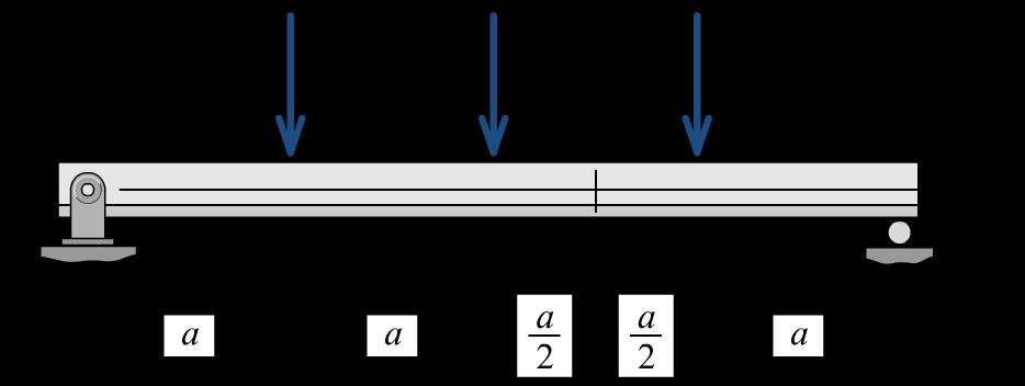
P8.26 A small aluminum alloy [E = 70 GPa] tee shape is used as a simply supported beam as shown in Figure P8.26a. For this beam, a = 160 mm. The cross-sectional dimensions (Figure P8.26b) of the tee shape are b = 20 mm, d = 30 mm, and t = 6 mm. After loads are applied to the beam at B, C, and D, a compressive normal strain of 440 is measured from a strain gage located at c = 8 mm below the topmost edge of the tee stem. What is the applied load P?
Solution
Centroid location in y direction: (reference axis at bottom of shape)
Moment of inertia about the z axis:
(measured upward from bottom edge of section)
The y coordinate at the strain gage is:
The bending strain at H is thus:
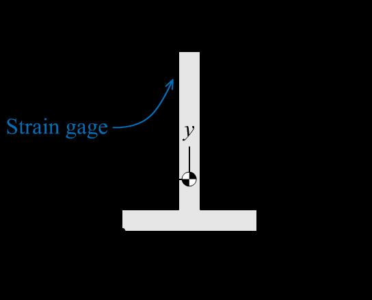 FIGURE P8.26a
FIGURE P8.26b
FIGURE P8.26a
FIGURE P8.26b
Shape Area Ai yi (from bottom) yi Ai (mm2) (mm) (mm3) Lower flange 120.00 3.0 360.00 Stem 144.00 18.0 2,592.00 264.00 2,952.00 3 2 2,952mm 11.182mm 264mm ii i yA y A ===
Shape IC idyy =− d²A IC + d²A (mm4) (mm) (mm4) (mm4) Lower flange 360.00 8.18 8,033.06 8,393.06 Stem 6,912 –6.82 6,694.21 13,606.21 Moment of inertia about the z axis (mm4) = 21,999.27
gage 30 mm8 mm11.182 mm10.818 mm ydcy=−−=−−=
( ) gage gage 66 gage gage 11.182mm 44010 mm/mm454.80510 mm/mm 10.818mm H H H H yy y y = ==−=
Mechanics of Materials: An Integrated Learning System, 4th Ed. Timothy A. Philpot
The bending stress at H is:
From the flexure moment, determine the bending moment that produces this bending stress at H:
Shear-force and bending-moment diagrams
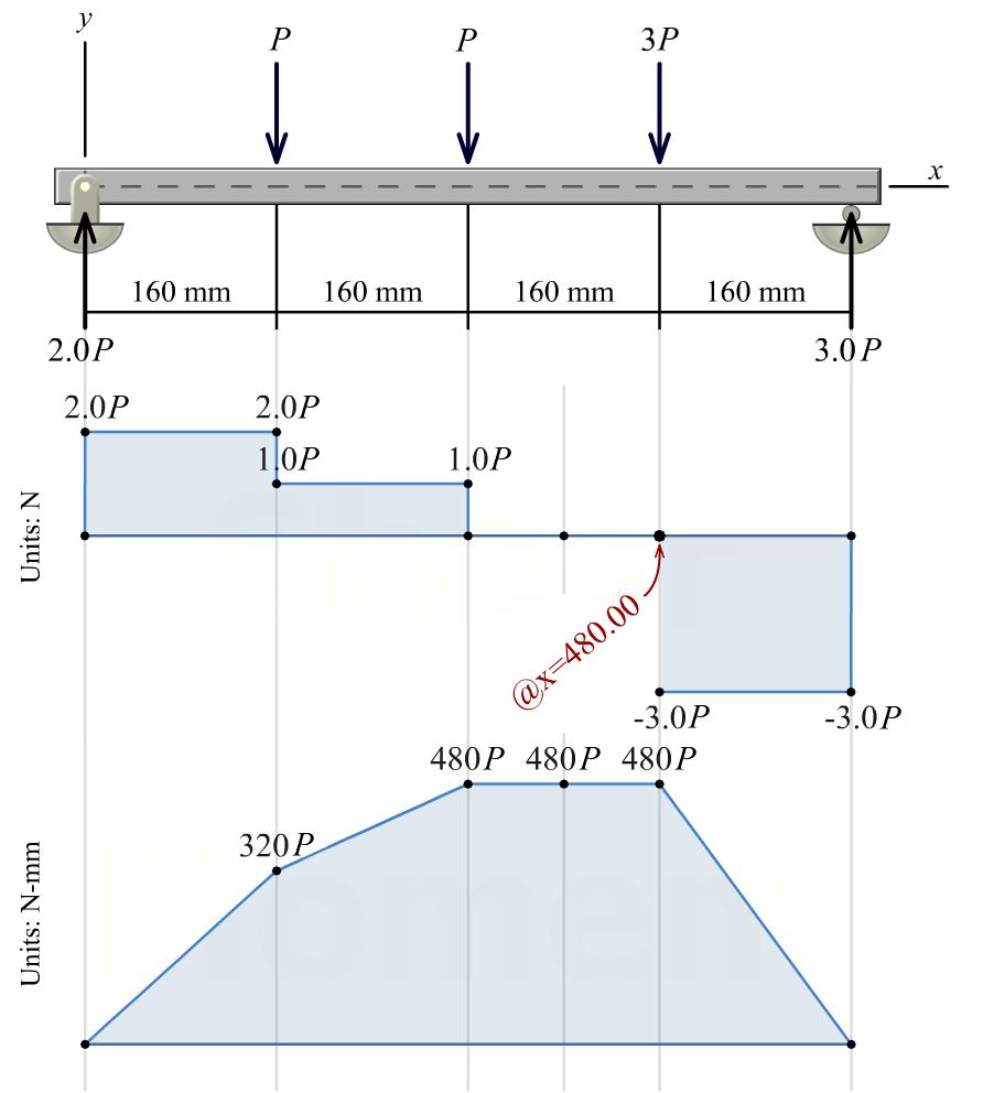
From the shear-force and bending-moment diagrams, we find that the bending moment at section 1–1 is:
Thus, the load P can be calculated as:
( )( ) 6
mm/mm31.836MPa xx E ===
70,000MPa454.80510
( )( ) 24
x z xz My I I M y =− =−=−=
31.836 N/mm21,999.27 mm 62,633.6 Nmm 11.182 mm
( )480mm MP =
P
= =
( ) 480 mm62,633.6 Nmm 130.5 N
P
Ans.
Mechanics of Materials: An Integrated Learning System, 4th Ed. Timothy A. Philpot
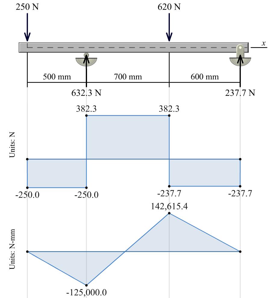
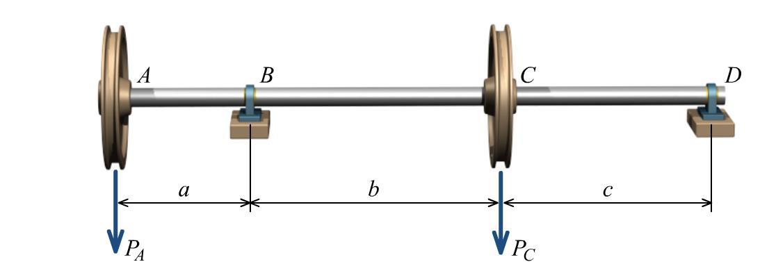
P8.27 A solid steel shaft supports loads PA = 250 N and PC = 620 N as shown in Figure P8.27. Assume a = 500 mm, b = 700 mm, and c = 600 mm. The bearing at B can be idealized as a roller support and the bearing at D can be idealized as a pin support. If the allowable bending stress is 105 MPa, determine the minimum diameter that can be used for the shaft.
Solution
Shear-force and bending-moment diagrams
Maximum bending moment magnitude M = 142,615.4 N-mm
Minimum required section modulus
Section modulus for solid circular section
FIGURE P8.27
3 2 142,615.4 N-mm 1,358.242 mm 105 N/mm x x M S M S =
3 32 d S = Minimum shaft diameter 3 3 1,358.242 mm 24.0 mm 32 d d Ans.
Mechanics of Materials: An Integrated Learning System, 4th Ed. Timothy A. Philpot
P8.28 A simply supported wood beam (Figure P8.28a/29a) with a span of L = 6 m supports a uniformly distributed load of w0. The beam width is b = 120 mm and the beam height is h = 300 mm (Figure P8.28b/29b). The allowable bending stress of the wood is 8.0 MPa. Calculate the magnitude of the maximum load w0 that may be carried by the beam.
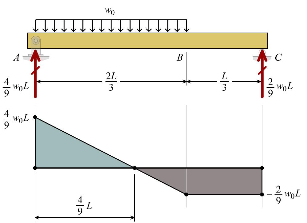
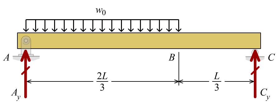
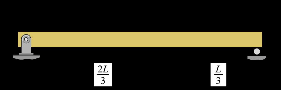 FIGURE P8.28a/29a
Solution Beam equilibrium: 0 0 0 0 2 0 33 2 9 22 0 33 4 9 Ay y Cy y LL MwCL CwL LL MwAL AwL =−+= = =−= = Shear-force diagram Maximum bending moment from found from shear-force diagram max0 2 0 144 299 8 81 MwLL wL = = Allowable bending moment: ( )( ) 32 2 63 /12 /26 120 mm300 mm 6 1.810 mm Ibhbh S ch === = =
FIGURE P8.28b/29b
Mechanics of Materials: An Integrated Learning System, 4th Ed. Timothy A. Philpot
Maximum allowable bending moment M:
( )( ) 2636 8 N/mm1.810 mm14.410 Nmm14.4 kNm x x M S MS ===
( ) ( ) 2 0 0 2 8 14.4 kNm 81 81 14.4 kNm 8 4.05 kN/m 6 m wL w = Ans.
Maximum load w0 that may be carried by the beam:
Mechanics of Materials: An Integrated Learning System, 4th Ed. Timothy A. Philpot
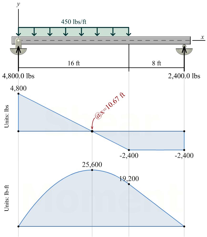
P8.29 A simply supported wood beam (Figure P8.28a/29a) with a span of L = 24 ft supports a uniformly distributed load of w0 = 450 lb/ft. The allowable bending stress of the wood is 1,200 psi. If the aspect ratio of the solid rectangular wood beam is specified as h/b = 3.0 (Figure P8.28b/29b), calculate the minimum width b that can be used for the beam.
Solution
Shear-force and bending-moment diagrams
Maximum bending moment magnitude M = 25,600 lb ft = 307,200 lb in.
Minimum required section modulus
2 307,200lbin. 256in. 1,200lb/in.
Section modulus for solid rectangular section
Theaspectratioofthesolidrectangularwoodbeam isspecifiedas h/b =3.0;therefore,thesectionmodulus can be expressed as:
Minimum allowable beam width
The corresponding beam height h is
FIGURE P8.28a/29a
FIGURE P8.28b/29b
3
x x M S M S =
/26 Ibhbh S ch ===
32 /12
22 3 (3.0) 1.5 66
Sb ===
bhbb
331.5256 in. 5.547 in 5.5 i 5n. b b = Ans.
( )
/3.03.03.05.54716.64 in. hbhb====
Mechanics of Materials: An Integrated Learning System, 4th Ed. Timothy A. Philpot
P8.30 A cantilever timber beam (Figure P8.30a/31a) with a span of L = 4.25 m supports a linearly distributed load with maximum intensity of w0 = 5.5 kN/m. The allowable bending stress of the wood is 7.0 MPa. If the aspect ratio of the solid rectangular timber is specified as h/b = 0.67 (Figure P8.30b/31b), determine the minimum width b that can be used for the beam.
Solution
Maximum moment magnitude: The maximum bending moment magnitude in the cantilever beam occurs at support A:
The aspect ratio of the solid rectangular wood beam is specified as h/b = 0.67; therefore, the section modulus can be expressed as:

 FIGURE P8.30a/31a
FIGURE P8.30b/31b
FIGURE P8.30a/31a
FIGURE P8.30b/31b
( )( )2 2 00 max 5.5kN/m4.25m 16.5573kNm16,557.3Nm 2366 wLwL L M =====
modulus ( )( ) 3 2 16,557.3Nm1,000mm/m 2,365,327.4 mm 7.0 N/mm x x MM S S ==
32 /12 /26 Ibhbh S ch ===
Minimum required section
Section modulus for solid rectangular section
( )2 23 3 0.67 0.4489 0.074817 666 bb bhb Sb ==== Minimum allowable beam width 330.0748172,365,327.4 mm 316.202 mm 316 mm b b = Ans. The corresponding beam height h is ( ) /0.67 0.670.67316.202 mm 212 mm hb hb = ===
Mechanics of Materials: An Integrated Learning System, 4th Ed. Timothy A. Philpot
P8.31 A cantilever timber beam (Figure P8.30a/31a) with a span of L = 14 ft supports a linearly distributed load with maximum intensity of w0 The beam width is b = 15 in. and the beam height is h = 10 in. (Figure P8.30b/31b). The allowable bending stress of the wood is 1,000 psi. Calculate the magnitude of the maximum load w0 that may be carried by the beam.
Solution
Section modulus for rectangular cross section about horizontal centroidal axis
Maximum allowable moment
Maximum moment magnitude: The maximum bending moment magnitude in the cantilever beam occurs at support A:
FIGURE P8.30a/31a
FIGURE P8.30b/31b
( )( )
2
66 bh S ===
2
3 15in.10 in. 250 in.
(
x x M S MS = ====
)( ) 23 1,000 lb/in.250 in.250,000 lbin.20,833.33lbft
2 00 max 236 wLLwL M ==
w0: ( ) ( ) ( ) 2 2 0 0 0 2 14 ft 20,833.33 lbft 66 620,833.33 lbft 637.755 lb/ft 14 638 lb/f ft t w wL w = == Ans.
Solve for the distributed load
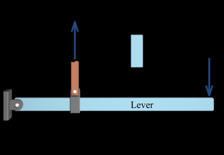
P8.32 The lever shown in Figure P8.32 must exert a force of P = 2,700 lbs at B as shown. The lever lengths are a = 10.5 in. and b = 46.0 in. The allowable bending stress for the lever is 12,000 psi. If the lever height h is to be three times the lever thickness t (i.e., h/t = 3), what is the minimum thickness t that can be used for the lever?
Solution Equilibrium
Maximum bending moment: The maximum bending moment magnitude in the lever occurs at B: ( ) ( )( ) max 616.304 lb46.0 in.10.5 in.21,878.8 lbin.
Minimum required section modulus
21,878.8 lbin.1.8232 in. 12,000 lb/in.
Section modulus for solid rectangular section 32 /12 /26 Ithth
The aspect ratio of the solid rectangular lever is specified as h/t = 3; therefore, the section modulus can be expressed as:
Minimum allowable lever thickness 331.51.8232
The corresponding lever height h is
4th Ed. Timothy A. Philpot
Mechanics of Materials: An Integrated Learning System,
FIGURE P8.32
( )
02,700 lb616.304 46.0lb in. A a MPaQbQP b =−====
10.5 in.
MQba=−=−=
3 2
x x M S M S ==
S
===
ch
( )2 2 3 3 1.5 66 tt th St ===
1.067. . in t t
in
Ans.
(
ht ht = ===
) /3 331.067 in. 3.20 in.
Mechanics of Materials: An Integrated Learning System,
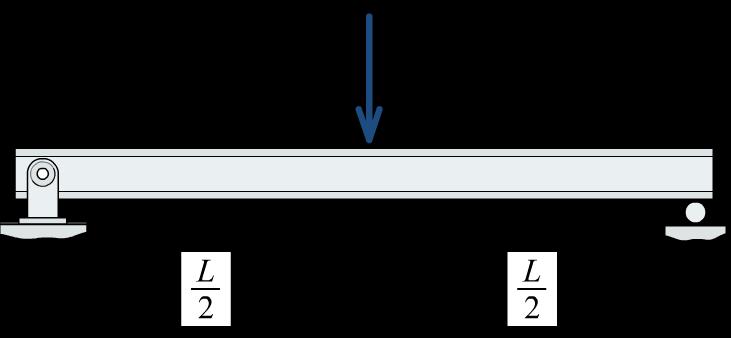
P8.33 The beam shown in Figure P8.33 will be constructed from a standard steel W-shape using an allowable bending stress of 30 ksi. The beam span is L = 24 ft, and the beam loads are w = 1.5 kips/ft and P = 20 kips.
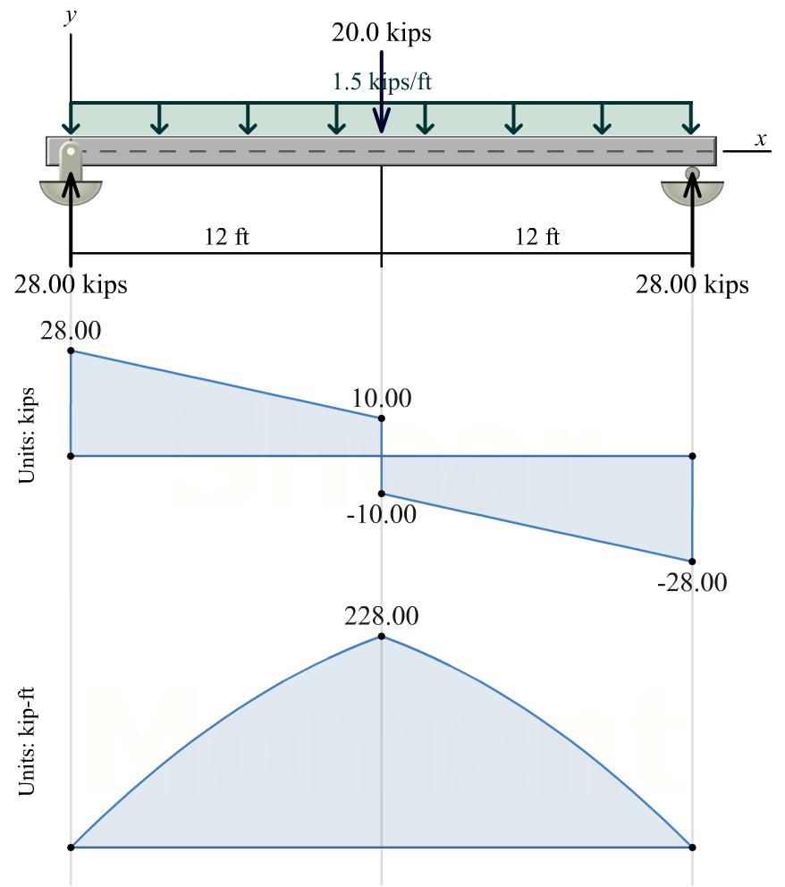
(a) Develop a list of five acceptable shapes that could be used for this beam. Include the most economical W14, W16, W18, W21, and W24 shapes on the list of possibilities.
(b) Select the most economical W shape for this beam.
Solution
Shear-force and bending-moment diagrams
Maximum bending moment magnitude M = 228 kip·ft
Minimum required section modulus
228 kipft12 in./ft 91.2 in. 30 kips/in.
(a) Acceptable steel W-shapes
68,103in.
57,92.2in. W18 55,98.3in.
W21 50,94.5in. W24 55,114in.
(b) Most economical W-shape W21 50 Ans.
th Ed.
Philpot
4
Timothy A.
FIGURE P8.33
( )( ) 3
x x M S M S =
2
3 3 3 3 3 W14
W16
S S S S S = = = = =
Mechanics of Materials: An Integrated Learning System,
P8.34 The beam shown in Figure P8.34 will be constructed from a standard steel W-shape using an allowable bending stress of 30 ksi. The beam span is L = 24 ft, and the beam loads are w = 1,100 lb/ft and 2w = 2,200 lb/ft.
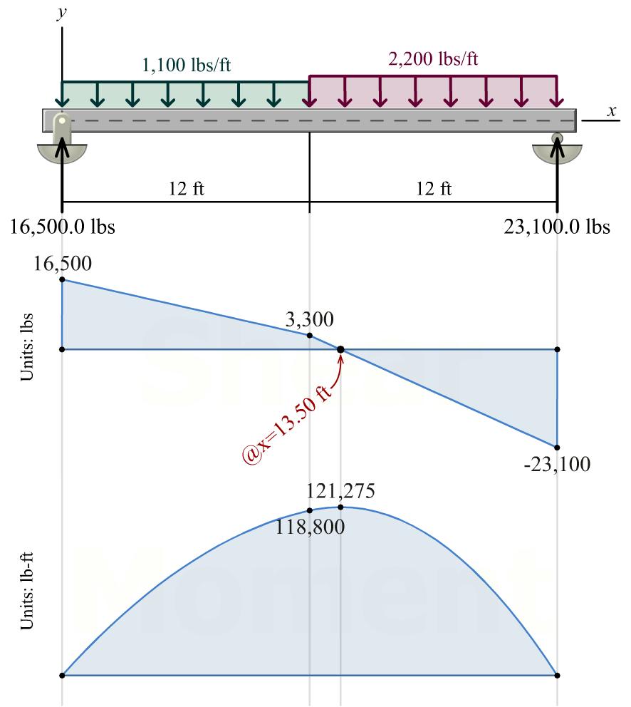
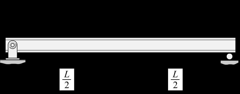
(a) Develop a list of four acceptable shapes that could be used for this beam. Include the most economical W10, W12, W14, and W16 shapes on the list of possibilities.
(b) Select the most economical W shape for this beam.
Solution
Shear-force and bending-moment diagrams
Maximum bending moment magnitude M = 121.275 kip·ft
Minimum required section modulus
(a) Acceptable steel W-shapes
(b) Most economical W-shape
Ans.
th Ed.
4
Timothy A. Philpot
FIGURE P8.34
( )( ) 3 2 121.275 kipft12 in./ft 48.51 in.
kips/in. x x M S M S =
30
3 3 3 3 W10 45,49.1 in. W12 40,51.5 in. W14 34,48.6 in. W16 40,64.7 in. S S S S = = = =
W14 34
Mechanics of Materials: An Integrated Learning System, 4th
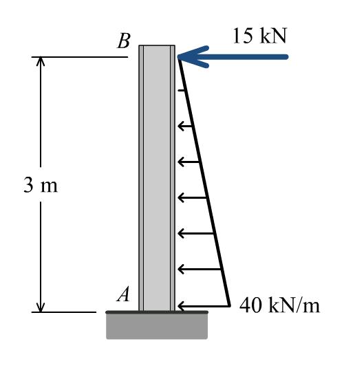
P8.35 The beam shown in Figure P8.35 will be constructed from a standard steel W-shape using an allowable bending stress of 165 MPa.
(a) Develop a list of four acceptable shapes that could be used for this beam. Include the most economical W310, W360, W410, and W460 shapes on the list of possibilities.
(b) Select the most economical W shape for this beam.
Maximum moment magnitude: The maximum bending moment magnitude occurs at the base of the cantilever beam:
Ed. Timothy A. Philpot
FIGURE P8.35
Solution
max 6 11 (15kN)(3.0m)(40kN/m)(3.0m)(3.0m) 23 105.0kN-m105.010 N-mm M =+ == Minimum required section modulus 2 33 2 (105.0 kN-m)(1,000) 63610 mm 165 N/mm x x M S M S == (a) Acceptable steel W-shapes 33 33 33 33 W31060,84410 mm W36044,68810 mm W41046.1,77310 mm W46052,94410 mm S S S S = = = = (b) Most economical W-shape W36044 Ans.
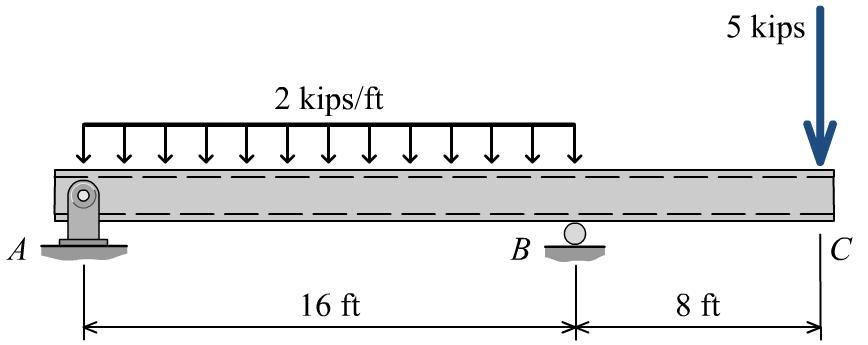
P8.36 The beam shown in Figure P8.36 will be constructed from a standard steel HSS-shape using an allowable bending stress of 30 ksi.
(a) Develop a list of three acceptable shapes that could be used for this beam. On this list, include the most economical HSS8, HSS10, and HSS12 shapes.
(b) Select the most economical HSS-shape for this beam.
Solution
Shear-force and bending-moment diagrams
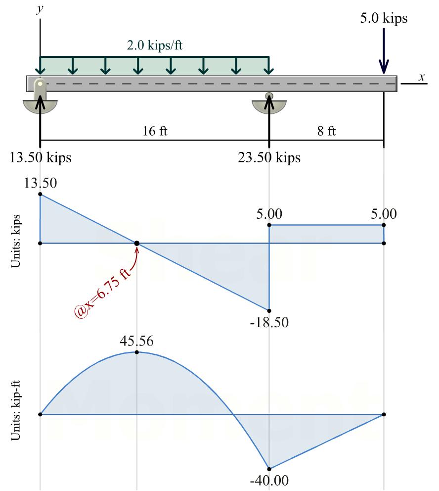
Maximum bending moment magnitude M = 45.56 kip ft
Minimum required section modulus
(a) Acceptable steel HSS shapes
are acceptable
(b) Most economical HSS shape
Learning System, 4th Ed. Timothy A. Philpot
Mechanics of Materials: An Integrated
FIGURE P8.36
( )( ) 3 45.56kipft12in./ft 18.22in. 30ksi x x M S M S =
3 3 3 3
HSS1043/8,20.8
HSS1063/8,27.4
HSS1263/8,35.9
HSS1283/8,43.7
S S S = = = =
HSS8none
in.
in.
in.
in. S
HSS1043/8
Solution manual
Mechanics of Materials: An Integrated Learning System 4th Edition by Philpot Visit TestBankBell.com to get complete for all chapters
Ans.
for
