VALVE CLEARANCE CHECK AND ADJUSTMENT Results:
DIESEL ENGINE
3. Turn the crankshaft pulley clockwise until No.1 cylinder TDC mark on the flywheel (A) aligns with the index mark on the flywheel housing (B) or plate. 4. Try to move both No. 1 cylinder rocker arms or push rods. NOTE: If the rocker arm push rods are not loose, rotate flywheel one revolution (360°). If both rocker arm push rods are loose, the piston is at TDC on compression stroke.
A
B E
1
I
E
2
I
E
3
I
E
4
I
C T6479AB M91893
• If the slow idle rpm is not according to specifications, loosen the nut (A) and turn the slow idle stop screw (B). After adjustment, tighten the nut.
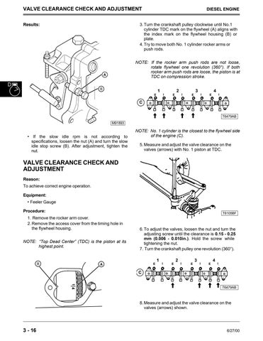
NOTE: No. 1 cylinder is the closest to the flywheel side of the engine (C). 5. Measure and adjust the valve clearance on the valves (arrows) with No. 1 piston at TDC.
VALVE CLEARANCE CHECK AND ADJUSTMENT Reason: To achieve correct engine operation. Equipment: • Feeler Gauge Procedure:
T6105BF
1. Remove the rocker arm cover. 2. Remove the access cover from the timing hole in the flywheel housing. NOTE: “Top Dead Center” (TDC) is the piston at its highest point.
B
6. To adjust the valves, loosen the nut and turn the adjusting screw until the clearance is 0.15 - 0.25 mm (0.006 - 0.010in.). Hold the screw while tightening the nut. 7. Turn the crankshaft pulley one revolution (360°).
E
A
1
I
E
2
I
E
3
I
E
4
I
C 1 4
T6479AB
8. Measure and adjust the valve clearance on the valves (arrows) shown.
3 - 16
6/27/00


