Type 2390 and 2390B FIELD WIRING COMPARTMENT
P
1
GND + + + LOAD -
-
24 V DC POWER SUPPLY
2 EARTH GROUND
SAFETY GROUND
TYPE 2390 STANDARD, FM APPROVED OR CSA CERTIFIED TRANSMITTERS
FIELD WIRING COMPARTMENT
P
1
+ + -
2
+ LOAD -
-
24 V DC POWER SUPPLY
2
TYPE 2390B LCIE (CENELEC) FLAMEPROOF TRANSMITTERS
B1983-1/IL
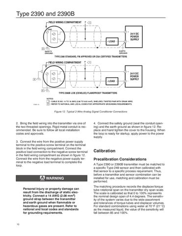
NOTES: 1 CABLE IS NO. 14 TO 18 AWG (2.08 TO 0.82 mm2), SHIELDED, TWISTED PAIR WITH DRAIN WIRE. 2 REFER TO NATIONAL AND LOCAL CODES FOR APPROPRIATE GROUNDING REQUIREMENTS.
Figure 12. Typical 2-Wire Analog Signal Conditioner Connections
2. Bring the field wiring into the transmitter via one of the two threaded openings. Rigid metal conduit is recommended. Be sure to follow all local installation codes and approvals. 3. Connect the wire from the positive power supply terminal to the positive screw terminal on the terminal block in the field wiring compartment. Connect the positive load connection to the negative screw terminal in the field wiring compartment as shown in figure 12. Connect the wire from the negative power supply terminal to the negative load terminal to complete the loop.
WARNING Personal injury or property damage can result from the discharge of static electricity. Connect a 14 AWG (2.08 mm2) ground strap between the transmitter and earth ground when flammable or hazardous gases are present. Refer to national and local codes and standards for grounding requirements.
10
4. Connect the safety ground (seal the conduit opening) and the earth ground as shown in figure 12. Replace and hand tighten the cover to the housing. When the loop is ready for startup, apply power to the power supply.
Calibration Precalibration Considerations A Type 2390 or 2390B transmitter must be matched to a specific Type 249 sensor and then calibrated with that sensor to a specific process requirement. Thus, before a transmitter and sensor combination can be installed for use, matching and calibration must be performed. The matching procedure records the displacer/torque tube rotational span on the transmitter dry span scale. The scale is calibrated so that 0 to 100% represents the nominal design span of 4.4 degrees. The sensitivity of the system varies due to the wide assortment and tolerances of torque tubes and displacer volumes. For standard combinations using water at 70"F (21"C) as the measured liquid, the value of the sensitivity will fall between 85 and 100%.